GoPLC Complete Manual — Full Reference
GoPLC Complete Manual
The complete GoPLC documentation in a single document — every getting-started walkthrough, every platform guide, every protocol driver, every ST library, in one searchable page. This is the same content as the per-topic guides, concatenated for offline reading and full-text search.
For a navigable index of the same material as separate pages, see the individual guides in this folder.
Table of Contents
- Part I: Getting Started
- Part II: Platform
- GoPLC IDE & Runtime Reference Guide
- GoPLC Visual Ladder Diagram Editor
- GoPLC Configuration Reference
- GoPLC REST API & Swagger Guide
- GOPLC Architecture
- GoPLC AI Assistant Guide
- GoPLC Node-RED Integration Guide
- GoPLC Authentication, RBAC, Audit Trail, and Electronic Signatures
- GoPLC System: Hardware Watchdog, Crash-Safe RETAIN, and UPS Monitoring
- GoPLC Hot Standby Redundancy
- GoPLC Alarm Management (ISA-18.2)
- GoPLC Edge Historian
- GoPLC Clustering & DataLayer Guide
- GoPLC MCP Server Guide
- AI Gateway: One Pi Controls Every PLC
- Part III: Programming
- GoPLC Timers, Counters & Function Blocks Guide
- GoPLC Math, String & Conversion Reference
- GoPLC Data Structures Guide
- GoPLC JSON Functions Guide
- GoPLC Debug & Logging Guide
- GoPLC Regular Expressions Guide
- GoPLC File I/O Guide
- GoPLC Database Guide
- GoPLC HTTP Client Guide
- GoPLC CSV & INI Parsing Guide
- GoPLC Cryptography & Security Guide
- GoPLC Motion Control Guide
- GoPLC Resilience & Caching Guide
- GoPLC SMTP Email Guide
- GoPLC OSCAT Library Guide
- Part IV: Hardware
- GoPLC HAL: Native GPIO, I2C, SPI, and ADC on Linux SBCs
- GoPLC Direct GPIO: Imperative Pin Access for Quick Prototyping
- GoPLC + Parallax Propeller 1: Hardware Interface Guide
- GoPLC + Parallax Propeller 2: Hardware Interface Guide
- GoPLC + Arduino Uno R4 WiFi: Hardware Interface Guide
- GoPLC + Teensy 4.0: Hardware Interface Guide
- GoPLC + Flipper Zero: Hardware Interface Guide
- GoPLC + Waveshare RP2040-Zero: Hardware Interface Guide
- GoPLC ESP32 HMI Dongle Guide
- GoPLC + Phidgets: Hardware Interface Guide
- Part V: Protocols
- GoPLC Modbus TCP Protocol Guide
- GoPLC Modbus RTU Protocol Guide
- GoPLC EtherNet/IP Protocol Guide
- GoPLC Siemens S7 Protocol Guide
- GoPLC OPC UA Protocol Guide
- GoPLC MQTT Protocol Guide
- GoPLC Omron FINS Protocol Guide
- GoPLC DNP3 Protocol Guide
- GoPLC IEC 60870-5-104 Protocol Guide
- GoPLC BACnet Protocol Guide
- GoPLC SNMP Protocol Guide
- GoPLC DF1 Protocol Guide
- GoPLC Sparkplug B Protocol Guide
- GoPLC SEL Protective Relay Protocol Guide
- GoPLC CAN Bus: SocketCAN, CAN FD, J1939, OBD-II, and DBC
- GoPLC InfluxDB Integration Guide
- GoPLC G-code: CNC, Laser & 3D Printer Interface Guide
- GoPLC Protocol Analyzer & Store-and-Forward Guide
- GoPLC NMEA & GPS Guide
- GoPLC Entertainment & Show Control Guide
- GoPLC Specialized Utilities Guide
- Part VI: Events & Integration
Part I: Getting Started
Getting Started with GoPLC
Download and Install
Requirements
- Any Linux machine: Raspberry Pi (2/3/4/5), server, VM, or desktop
- x86_64 (Intel/AMD) or ARM64 (Raspberry Pi, ARM SBCs)
- 150MB RAM, 100MB disk
- A web browser on any device on the same network
Download
Get the latest release from the GoPLC download page or extract the tarball directly:
# Download (substitute your platform: linux-amd64 or linux-arm64)
tar xzf goplc-v1.0.535-linux-amd64.tar.gz
cd goplc-v1.0.535-linux-amd64
Install as a System Service
The included installer sets up GoPLC as a systemd service that starts automatically on boot:
sudo ./install.shThis will:
- Copy the
goplcbinary to/usr/local/bin/ - Create a systemd service (
goplc.service) - Start GoPLC on port 8082 by default
- Set up Node-RED with Dashboard 2.0
Or Run Manually
If you prefer to run without installing:
./goplc --api-port 8082Verify It’s Running
Open a browser and go to:
http://<your-machine-ip>:8082/ide/You should see the GoPLC Web IDE. If you’re on the same machine, use http://localhost:8082/ide/.
Tip: If the page doesn’t load, check that the port is open in your firewall:
sudo ufw allow 8082/tcp
The Web IDE
The IDE is your main workspace. Here’s what you’ll see:
Left Panel — Program Explorer
- Programs — your ST (Structured Text) source files
- Tasks — execution containers that run programs on a scan cycle
- Libraries — reusable function collections
Center — Code Editor
- Syntax-highlighted ST editor
- Click any program in the explorer to open it
Right Panel — Variable Monitor
- Live values of all variables, updated in real-time
- Search and filter variables by name
Top Bar
- Run/Stop — start and stop the PLC runtime
- Download — deploy your code to the runtime
- Online — toggle online mode to see live values in the editor
- AI Assistant — generate ST code, HMI pages, or Node-RED flows
Bottom Bar
- Messages — compilation errors and warnings
- Faults — runtime fault log
License Activation
GoPLC runs in demo mode for 2 hours without a license. After that, you’ll need to activate with a license key.
Find Your Install ID
In the IDE, click the license indicator in the top bar. You’ll see your Installation ID — a unique identifier for this machine.
Or via the API:
curl http://localhost:8082/api/licenseActivate Your License
If you have a cloud license key (format: GOPLC-XXXX-XXXX-XXXX-XXXX):
Option A — From the IDE: Click the license indicator → paste your key → click Activate.
Option B — From the API:
curl -X POST http://localhost:8082/api/license/activate \
  -H "Content-Type: application/json" \
  -d '{"unlock_code": "GOPLC-XXXX-XXXX-XXXX-XXXX"}'
The key activates once and is cached permanently — no internet required after the first activation.
Your First Program
Let’s create a simple counter that increments every second and calculates a sine wave. This demonstrates variables, timers, math, and the scan cycle.
Step 1: Create the Program
In the IDE, click New Program (+ icon) and name it my_counter.
Paste this code:
PROGRAM my_counter
VAR
    count       : DINT := 0;
    prev_second : DINT := 0;
    now_s       : DINT;
    sine_value  : REAL := 0.0;
    running     : BOOL := TRUE;
END_VAR

(* Increment counter once per second *)
now_s := NOW_MS() / 1000;

IF now_s <> prev_second THEN
    prev_second := now_s;

    IF running THEN
        count := count + 1;
    END_IF;
END_IF;

(* Calculate a sine wave from the counter *)
sine_value := SIN(INT_TO_REAL(count) * 0.1) * 100.0;

END_PROGRAM
Step 2: Deploy
Click the Download button (or press Ctrl+D). This compiles your code and deploys it to the runtime. If there are errors, they’ll appear in the Messages panel at the bottom.
Step 3: Start the Runtime
Click the Run button (green play icon). The runtime starts executing your program on its configured scan cycle.
Step 4: Watch It Run
Click Online to enable online mode. You’ll see live values next to each variable in the editor:
countincrementing every second: 1, 2, 3, 4…sine_valueoscillating: 9.98, 19.86, 29.55, 38.94…runningshowing TRUE
You can also see all variables in the Monitor panel on the right.
Step 5: Interact
Try changing running to FALSE from the monitor panel — the counter stops.
Set it back to TRUE — it resumes. This is live interaction with a running PLC.
Add a Task Configuration
By default, GoPLC creates a MainTask for your program. You can customize the scan cycle time and add multiple tasks.
From the IDE
Click the Tasks section in the left panel. You’ll see your task with:
- Scan Time — how often the program runs (default 100ms = 10 times/second)
- Programs — which programs are assigned to this task
- Watchdog — maximum allowed scan time before a fault
Multiple Tasks
You can create separate tasks for different purposes:
| Task | Scan Time | Purpose |
|---|---|---|
| fast_control | 10ms | Time-critical control loops |
| normal | 100ms | General logic, I/O scanning |
| slow_logging | 1000ms | Data logging, diagnostics |
Each task runs independently with its own scan cycle.
Node-RED is Already Running
GoPLC bundles Node-RED with 7 custom PLC nodes and Dashboard 2.0. It started automatically when GoPLC launched.
Open Node-RED
Navigate to:
http://<your-machine-ip>:8082/nodered/Built-in GOPLC Nodes
In the Node-RED palette (left side), you’ll find the goplc category with:
| Node | Purpose |
|---|---|
| goplc-connection | Auto-discovers the local GoPLC instance |
| goplc-read | Read a variable value (REST poll) |
| goplc-write | Write a value to a variable |
| goplc-subscribe | Real-time variable updates (WebSocket) |
| goplc-runtime | Start/stop/pause the runtime |
| goplc-task | Task info and control |
| goplc-cluster | Access minion nodes via boss proxy |
Quick Dashboard Example
Try this flow to display your counter on a phone dashboard:
- Drag a goplc-subscribe node onto the canvas
- Double-click it, set Variable to
my_counter.count - Drag a dashboard gauge node and connect them
- Click Deploy
- Open the dashboard:
http://<your-machine-ip>:8082/nodered/dashboard/
You’ll see your counter value updating live on a gauge widget — accessible from any phone or tablet on your network.
What’s Next?
You now have a running PLC with a web IDE, live monitoring, and a Node-RED dashboard. Here’s where to go from here:
Learn More
| Guide | What You’ll Build |
|---|---|
| Home Automation | MQTT sensors, InfluxDB logging, Home Assistant integration |
| Washing Machine Controller | Full appliance controller with Modbus I/O, state machine, phone dashboard |
Explore the IDE
- AI Assistant — Ask it to generate programs, HMI pages, or Node-RED flows
- HMI Builder — Create custom web dashboards at
/hmi/ - Step Debugger — Set breakpoints, step through code, inspect the call stack
- Protocol Analyzer — Capture and decode industrial protocol traffic
Connect Real Hardware
GoPLC supports 14+ industrial protocols out of the box:
| Protocol | Use Case |
|---|---|
| Modbus TCP/RTU | Most common — PLCs, VFDs, sensors, relay modules |
| MQTT | IoT devices, Home Assistant, cloud |
| OPC UA | Interoperability with other PLCs and SCADA |
| EtherNet/IP | Allen-Bradley / Rockwell devices |
| S7 | Siemens devices |
| FINS | Omron devices |
| BACnet | Building automation |
| DNP3 | Utility / SCADA |
Scale Up
- Clustering — Distribute workloads across multiple GoPLC instances
- Docker — Deploy as containers for production
- ctrlX CORE — Run as a snap on Bosch Rexroth industrial controllers
Get Help
- Web IDE built-in docs: click Docs in the top bar
- API reference:
http://<your-ip>:8082/api/docs - Function search:
http://<your-ip>:8082/api/docs/functions?search=keyword
GoPLC Home Automation Hub
Why GoPLC for Home Automation?
Home Assistant is great for coordination and UI. But it’s not a real-time controller — it’s an event-driven Python app. When you need deterministic scan-based control (HVAC sequencing, irrigation scheduling, pool chemistry, lighting scenes with precise timing), a PLC runtime is the right tool. GoPLC bridges both worlds:
- Deterministic control loops — 100ms scan cycle, watchdog-protected
- Native MQTT — Publish/subscribe directly from Structured Text, no plugins
- Native InfluxDB — Write time-series data directly from ST, no middleware
- Built-in MQTT broker — No external Mosquitto needed (optional)
- Node-RED bundled — Dashboard 2.0 for custom panels, flow logic for glue
- Home Assistant integration — MQTT discovery, HA sees GoPLC devices automatically
- 1,600+ ST functions — Timers, PID, math, string, JSON, HTTP, scheduling
System Architecture
┌─────────────────────────────────────────────────────────────────┐
│ Raspberry Pi (or any Linux box) │
│ │
│ ┌──────────┐ ┌──────────┐ ┌──────────────┐ │
│ │ GoPLC │──►│ Node-RED │──►│ Dashboard 2.0│ │
│ │ Runtime │ │ (bundled)│ │ (phone/tablet)│ │
│ │ │ └──────────┘ └──────────────┘ │
│ │ MQTT ◄──┼─────────────────────────────────┐ │
│ │ InfluxDB│ │ │
│ └────┬─────┘ │ │
│ │ MQTT │ │
└───────┼────────────────────────────────────────┼───────────────┘
│ │
┌──────┴──────┐ ┌──────┴──────┐
│ MQTT Broker │◄─────────────────────────│ Home │
│ (built-in │ MQTT │ Assistant │
│ or extern) │◄───────────┐ │ (optional) │
└──────┬──────┘ │ └─────────────┘
│ │
┌──────┴──────┐ ┌─────┴───────┐
│ InfluxDB │ │ IoT Devices │
│ (Docker) │ │ Zigbee/WiFi │
│ │ │ Shelly/Tasmota│
│ Grafana │ │ ESP32/sensors│
└─────────────┘ └─────────────┘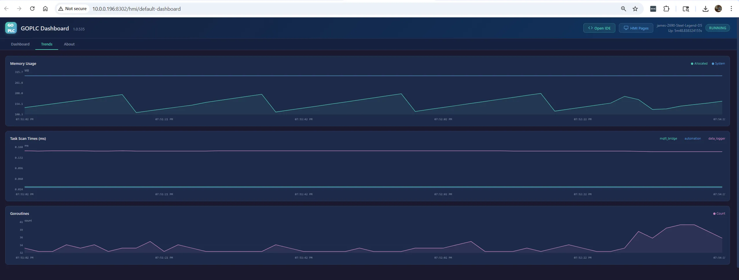 GoPLC built-in dashboard — memory usage, scan times, and goroutines for all 3 tasks
Three integration paths work simultaneously:
- GoPLC ↔ MQTT ↔ Devices — Direct control of Shelly, Tasmota, Zigbee2MQTT devices
- GoPLC → InfluxDB → Grafana — Long-term data logging and visualization
- GoPLC ↔ MQTT ↔ Home Assistant — Voice control, automations, mobile app
Prerequisites
| Component | Purpose | Where |
|---|---|---|
| GoPLC on Linux | Automation runtime | Raspberry Pi or server |
| MQTT broker | Message bus | GoPLC built-in, or Mosquitto in Docker |
| InfluxDB v2 | Time-series database | Docker on same machine or separate |
| Grafana | Dashboards and alerts | Docker alongside InfluxDB |
| Home Assistant | Voice, mobile, automations | Separate Pi or Docker (optional) |
| IoT devices | Sensors and actuators | Shelly plugs, Zigbee sensors, ESP32, etc. |
Docker Compose for InfluxDB + Grafana
version: '3'
services:
  influxdb:
    image: influxdb:2
    container_name: influxdb
    ports:
      - "8086:8086"
    volumes:
      - influxdb-data:/var/lib/influxdb2
    environment:
      - DOCKER_INFLUXDB_INIT_MODE=setup
      - DOCKER_INFLUXDB_INIT_USERNAME=admin
      - DOCKER_INFLUXDB_INIT_PASSWORD=changeme123
      - DOCKER_INFLUXDB_INIT_ORG=homelab
      - DOCKER_INFLUXDB_INIT_BUCKET=home
      - DOCKER_INFLUXDB_INIT_RETENTION=30d
      - DOCKER_INFLUXDB_INIT_ADMIN_TOKEN=my-home-token

  grafana:
    image: grafana/grafana
    container_name: grafana
    ports:
      - "3000:3000"
    volumes:
      - grafana-data:/var/lib/grafana
    depends_on:
      - influxdb

volumes:
  influxdb-data:
  grafana-data:
Example Project: Whole-House Monitoring and Control
This example monitors temperature/humidity in 4 rooms, controls smart plugs, logs everything to InfluxDB, and exposes devices to Home Assistant.
Devices Used
| Device | Protocol | MQTT Topic | Purpose |
|---|---|---|---|
| Zigbee temp/humidity sensors (x4) | Zigbee2MQTT | zigbee2mqtt/<name> | Room climate |
| Shelly Plug S (x4) | WiFi/MQTT | shellies/<id>/relay/0 | Smart plugs (lamps, fans) |
| Shelly H&T | WiFi/MQTT | shellies/<id>/sensor | Outdoor temp/humidity |
| ESP32 + DHT22 | WiFi/MQTT | esp32/garage/climate | Garage monitoring |
| Tasmota IR blaster | WiFi/MQTT | cmnd/<name>/irhvac | HVAC control |
ST Programs
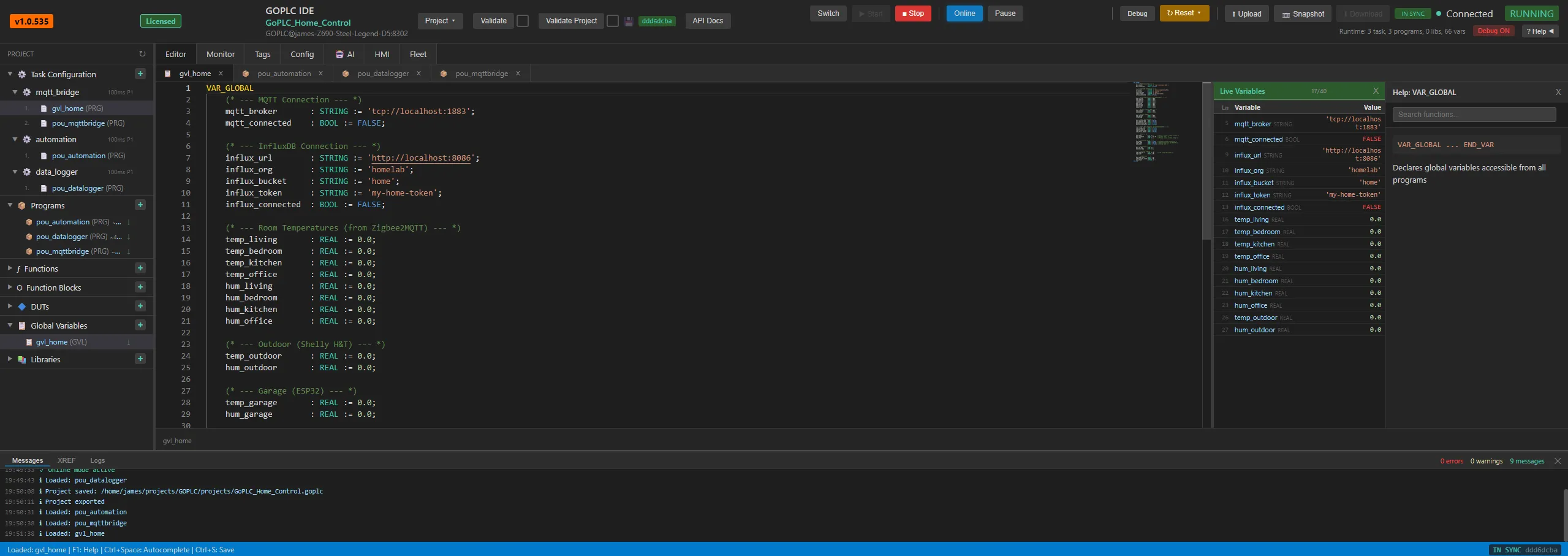 GoPLC Web IDE — GVL variables with live values in the monitor panel
GVL — Global Variables
VAR_GLOBAL
    (* --- MQTT Connection --- *)
    mqtt_broker       : STRING := 'tcp://localhost:1883';
    mqtt_connected    : BOOL := FALSE;

    (* --- InfluxDB Connection --- *)
    influx_url        : STRING := 'http://localhost:8086';
    influx_org        : STRING := 'homelab';
    influx_bucket     : STRING := 'home';
    influx_token      : STRING := 'my-home-token';
    influx_connected  : BOOL := FALSE;

    (* --- Room Temperatures (from Zigbee2MQTT) --- *)
    temp_living       : REAL := 0.0;
    temp_bedroom      : REAL := 0.0;
    temp_kitchen      : REAL := 0.0;
    temp_office       : REAL := 0.0;
    hum_living        : REAL := 0.0;
    hum_bedroom       : REAL := 0.0;
    hum_kitchen       : REAL := 0.0;
    hum_office        : REAL := 0.0;

    (* --- Outdoor (Shelly H&T) --- *)
    temp_outdoor      : REAL := 0.0;
    hum_outdoor       : REAL := 0.0;

    (* --- Garage (ESP32) --- *)
    temp_garage       : REAL := 0.0;
    hum_garage        : REAL := 0.0;

    (* --- Smart Plug States --- *)
    plug_living_lamp  : BOOL := FALSE;
    plug_bedroom_fan  : BOOL := FALSE;
    plug_kitchen_light: BOOL := FALSE;
    plug_office_heater: BOOL := FALSE;

    (* --- Smart Plug Commands (from dashboard/HA) --- *)
    cmd_living_lamp   : BOOL := FALSE;
    cmd_bedroom_fan   : BOOL := FALSE;
    cmd_kitchen_light : BOOL := FALSE;
    cmd_office_heater : BOOL := FALSE;

    (* --- HVAC --- *)
    hvac_mode         : INT := 0;      (* 0=off, 1=cool, 2=heat, 3=auto *)
    hvac_setpoint     : REAL := 22.0;  (* Target temp C *)
    hvac_fan          : INT := 1;      (* 0=auto, 1=low, 2=med, 3=high *)

    (* --- Automation Rules --- *)
    auto_mode         : BOOL := TRUE;  (* Enable/disable automations *)
    night_mode        : BOOL := FALSE; (* Reduced activity 22:00-06:00 *)
    away_mode         : BOOL := FALSE; (* Nobody home *)

    (* --- Scheduling --- *)
    hour_of_day       : INT := 0;
    minute_of_day     : INT := 0;

    (* --- InfluxDB logging --- *)
    log_interval_s    : INT := 30;     (* Log every 30 seconds *)
    log_timer         : DINT := 0;

    (* --- Diagnostics --- *)
    mqtt_msg_count    : DINT := 0;
    influx_write_count: DINT := 0;
    last_fault        : STRING := '';
END_VAR
POU_MqttBridge — MQTT Subscription and Publishing
PROGRAM POU_MqttBridge
VAR
    init_done       : BOOL := FALSE;
    json_msg        : STRING;
    msg_payload     : STRING;

    (* Previous plug states for edge detection *)
    prev_living     : BOOL := FALSE;
    prev_bedroom    : BOOL := FALSE;
    prev_kitchen    : BOOL := FALSE;
    prev_office     : BOOL := FALSE;
END_VAR

(* ============================================================
   SECTION 1: MQTT INITIALIZATION
   ============================================================ *)
IF NOT init_done THEN
    MQTT_CLIENT_CREATE('home', GVL.mqtt_broker, 'goplc-home');
    MQTT_CLIENT_CONNECT('home');
    init_done := TRUE;
END_IF;

GVL.mqtt_connected := MQTT_CLIENT_IS_CONNECTED('home');

IF NOT GVL.mqtt_connected THEN
    MQTT_CLIENT_CONNECT('home');
    RETURN;
END_IF;

(* ============================================================
   SECTION 2: SUBSCRIBE TO SENSOR TOPICS (once)
   ============================================================ *)
(* Zigbee2MQTT sensors publish JSON: {"temperature":21.5,"humidity":45} *)
MQTT_SUBSCRIBE('home', 'zigbee2mqtt/living_sensor');
MQTT_SUBSCRIBE('home', 'zigbee2mqtt/bedroom_sensor');
MQTT_SUBSCRIBE('home', 'zigbee2mqtt/kitchen_sensor');
MQTT_SUBSCRIBE('home', 'zigbee2mqtt/office_sensor');

(* Shelly H&T outdoor *)
MQTT_SUBSCRIBE('home', 'shellies/shelly_outdoor/sensor/temperature');
MQTT_SUBSCRIBE('home', 'shellies/shelly_outdoor/sensor/humidity');

(* ESP32 garage *)
MQTT_SUBSCRIBE('home', 'esp32/garage/temperature');
MQTT_SUBSCRIBE('home', 'esp32/garage/humidity');

(* Shelly plug status *)
MQTT_SUBSCRIBE('home', 'shellies/plug_living/relay/0');
MQTT_SUBSCRIBE('home', 'shellies/plug_bedroom/relay/0');
MQTT_SUBSCRIBE('home', 'shellies/plug_kitchen/relay/0');
MQTT_SUBSCRIBE('home', 'shellies/plug_office/relay/0');

(* Home Assistant commands (optional) *)
MQTT_SUBSCRIBE('home', 'goplc/cmd/hvac_mode');
MQTT_SUBSCRIBE('home', 'goplc/cmd/hvac_setpoint');
MQTT_SUBSCRIBE('home', 'goplc/cmd/away_mode');
MQTT_SUBSCRIBE('home', 'goplc/cmd/auto_mode');

(* ============================================================
   SECTION 3: READ SENSOR DATA
   Zigbee2MQTT publishes JSON — use GET_MESSAGE_JSON to parse.
   Shelly/ESP32 publish plain values.
   ============================================================ *)

(* --- Zigbee2MQTT rooms (JSON payloads) --- *)
IF MQTT_HAS_MESSAGE('home', 'zigbee2mqtt/living_sensor') THEN
    json_msg := MQTT_GET_MESSAGE('home', 'zigbee2mqtt/living_sensor');
    GVL.temp_living := TO_REAL(JSON_GET(json_msg, 'temperature'));
    GVL.hum_living  := TO_REAL(JSON_GET(json_msg, 'humidity'));
    GVL.mqtt_msg_count := GVL.mqtt_msg_count + 1;
END_IF;

IF MQTT_HAS_MESSAGE('home', 'zigbee2mqtt/bedroom_sensor') THEN
    json_msg := MQTT_GET_MESSAGE('home', 'zigbee2mqtt/bedroom_sensor');
    GVL.temp_bedroom := TO_REAL(JSON_GET(json_msg, 'temperature'));
    GVL.hum_bedroom  := TO_REAL(JSON_GET(json_msg, 'humidity'));
    GVL.mqtt_msg_count := GVL.mqtt_msg_count + 1;
END_IF;

IF MQTT_HAS_MESSAGE('home', 'zigbee2mqtt/kitchen_sensor') THEN
    json_msg := MQTT_GET_MESSAGE('home', 'zigbee2mqtt/kitchen_sensor');
    GVL.temp_kitchen := TO_REAL(JSON_GET(json_msg, 'temperature'));
    GVL.hum_kitchen  := TO_REAL(JSON_GET(json_msg, 'humidity'));
    GVL.mqtt_msg_count := GVL.mqtt_msg_count + 1;
END_IF;

IF MQTT_HAS_MESSAGE('home', 'zigbee2mqtt/office_sensor') THEN
    json_msg := MQTT_GET_MESSAGE('home', 'zigbee2mqtt/office_sensor');
    GVL.temp_office := TO_REAL(JSON_GET(json_msg, 'temperature'));
    GVL.hum_office  := TO_REAL(JSON_GET(json_msg, 'humidity'));
    GVL.mqtt_msg_count := GVL.mqtt_msg_count + 1;
END_IF;

(* --- Shelly outdoor (plain string values) --- *)
IF MQTT_HAS_MESSAGE('home', 'shellies/shelly_outdoor/sensor/temperature') THEN
    GVL.temp_outdoor := MQTT_GET_MESSAGE_REAL('home', 'shellies/shelly_outdoor/sensor/temperature');
END_IF;
IF MQTT_HAS_MESSAGE('home', 'shellies/shelly_outdoor/sensor/humidity') THEN
    GVL.hum_outdoor := MQTT_GET_MESSAGE_REAL('home', 'shellies/shelly_outdoor/sensor/humidity');
END_IF;

(* --- ESP32 garage (plain values) --- *)
IF MQTT_HAS_MESSAGE('home', 'esp32/garage/temperature') THEN
    GVL.temp_garage := MQTT_GET_MESSAGE_REAL('home', 'esp32/garage/temperature');
END_IF;
IF MQTT_HAS_MESSAGE('home', 'esp32/garage/humidity') THEN
    GVL.hum_garage := MQTT_GET_MESSAGE_REAL('home', 'esp32/garage/humidity');
END_IF;

(* --- Shelly plug states (on/off) --- *)
IF MQTT_HAS_MESSAGE('home', 'shellies/plug_living/relay/0') THEN
    GVL.plug_living_lamp := MQTT_GET_MESSAGE('home', 'shellies/plug_living/relay/0') = 'on';
END_IF;
IF MQTT_HAS_MESSAGE('home', 'shellies/plug_bedroom/relay/0') THEN
    GVL.plug_bedroom_fan := MQTT_GET_MESSAGE('home', 'shellies/plug_bedroom/relay/0') = 'on';
END_IF;
IF MQTT_HAS_MESSAGE('home', 'shellies/plug_kitchen/relay/0') THEN
    GVL.plug_kitchen_light := MQTT_GET_MESSAGE('home', 'shellies/plug_kitchen/relay/0') = 'on';
END_IF;
IF MQTT_HAS_MESSAGE('home', 'shellies/plug_office/relay/0') THEN
    GVL.plug_office_heater := MQTT_GET_MESSAGE('home', 'shellies/plug_office/relay/0') = 'on';
END_IF;

(* --- Home Assistant commands --- *)
IF MQTT_HAS_MESSAGE('home', 'goplc/cmd/hvac_mode') THEN
    GVL.hvac_mode := MQTT_GET_MESSAGE_INT('home', 'goplc/cmd/hvac_mode');
END_IF;
IF MQTT_HAS_MESSAGE('home', 'goplc/cmd/hvac_setpoint') THEN
    GVL.hvac_setpoint := MQTT_GET_MESSAGE_REAL('home', 'goplc/cmd/hvac_setpoint');
END_IF;
IF MQTT_HAS_MESSAGE('home', 'goplc/cmd/away_mode') THEN
    GVL.away_mode := MQTT_GET_MESSAGE_BOOL('home', 'goplc/cmd/away_mode');
END_IF;
IF MQTT_HAS_MESSAGE('home', 'goplc/cmd/auto_mode') THEN
    GVL.auto_mode := MQTT_GET_MESSAGE_BOOL('home', 'goplc/cmd/auto_mode');
END_IF;

(* ============================================================
   SECTION 4: WRITE PLUG COMMANDS (edge-triggered)
   Only publish on state change to avoid MQTT flooding.
   ============================================================ *)
IF GVL.cmd_living_lamp <> prev_living THEN
    prev_living := GVL.cmd_living_lamp;
    IF GVL.cmd_living_lamp THEN
        MQTT_PUBLISH('home', 'shellies/plug_living/relay/0/command', 'on');
    ELSE
        MQTT_PUBLISH('home', 'shellies/plug_living/relay/0/command', 'off');
    END_IF;
END_IF;

IF GVL.cmd_bedroom_fan <> prev_bedroom THEN
    prev_bedroom := GVL.cmd_bedroom_fan;
    IF GVL.cmd_bedroom_fan THEN
        MQTT_PUBLISH('home', 'shellies/plug_bedroom/relay/0/command', 'on');
    ELSE
        MQTT_PUBLISH('home', 'shellies/plug_bedroom/relay/0/command', 'off');
    END_IF;
END_IF;

IF GVL.cmd_kitchen_light <> prev_kitchen THEN
    prev_kitchen := GVL.cmd_kitchen_light;
    IF GVL.cmd_kitchen_light THEN
        MQTT_PUBLISH('home', 'shellies/plug_kitchen/relay/0/command', 'on');
    ELSE
        MQTT_PUBLISH('home', 'shellies/plug_kitchen/relay/0/command', 'off');
    END_IF;
END_IF;

IF GVL.cmd_office_heater <> prev_office THEN
    prev_office := GVL.cmd_office_heater;
    IF GVL.cmd_office_heater THEN
        MQTT_PUBLISH('home', 'shellies/plug_office/relay/0/command', 'on');
    ELSE
        MQTT_PUBLISH('home', 'shellies/plug_office/relay/0/command', 'off');
    END_IF;
END_IF;

(* ============================================================
   SECTION 5: PUBLISH STATE TO HOME ASSISTANT
   Publish GoPLC state so HA can display/automate with it.
   Use retained messages so HA gets current state on restart.
   ============================================================ *)
MQTT_PUBLISH_RETAINED('home', 'goplc/state/temp_living', REAL_TO_STRING(GVL.temp_living));
MQTT_PUBLISH_RETAINED('home', 'goplc/state/temp_bedroom', REAL_TO_STRING(GVL.temp_bedroom));
MQTT_PUBLISH_RETAINED('home', 'goplc/state/temp_kitchen', REAL_TO_STRING(GVL.temp_kitchen));
MQTT_PUBLISH_RETAINED('home', 'goplc/state/temp_office', REAL_TO_STRING(GVL.temp_office));
MQTT_PUBLISH_RETAINED('home', 'goplc/state/temp_outdoor', REAL_TO_STRING(GVL.temp_outdoor));
MQTT_PUBLISH_RETAINED('home', 'goplc/state/temp_garage', REAL_TO_STRING(GVL.temp_garage));
MQTT_PUBLISH_RETAINED('home', 'goplc/state/hvac_mode', INT_TO_STRING(GVL.hvac_mode));
MQTT_PUBLISH_RETAINED('home', 'goplc/state/away_mode', BOOL_TO_STRING(GVL.away_mode));

END_PROGRAM
POU_Automation — Control Logic
PROGRAM POU_Automation
VAR
    prev_second    : DINT := 0;
    now_s          : DINT;
    hvac_cmd       : STRING;
    hvac_json      : STRING;
END_VAR

(* ============================================================
   TIMEKEEPING
   ============================================================ *)
now_s := NOW_MS() / 1000;
IF now_s <> prev_second THEN
    prev_second := now_s;

    (* Update time of day from wall clock — NOW_TIME() returns "HH:MM:SS" *)
    GVL.hour_of_day := STRING_TO_INT(LEFT(NOW_TIME(), 2));
    GVL.minute_of_day := STRING_TO_INT(MID(NOW_TIME(), 4, 2));

    (* Night mode: 22:00 to 06:00 *)
    GVL.night_mode := (GVL.hour_of_day >= 22) OR (GVL.hour_of_day < 6);
END_IF;

IF NOT GVL.auto_mode THEN
    RETURN;  (* Manual mode — no automations *)
END_IF;

(* ============================================================
   RULE 1: Office heater — ON if office < setpoint - 1, OFF if > setpoint
   Only during working hours (08:00-18:00), not in away mode.
   ============================================================ *)
IF NOT GVL.away_mode AND GVL.hour_of_day >= 8 AND GVL.hour_of_day < 18 THEN
    IF GVL.temp_office < (GVL.hvac_setpoint - 1.0) THEN
        GVL.cmd_office_heater := TRUE;
    ELSIF GVL.temp_office > GVL.hvac_setpoint THEN
        GVL.cmd_office_heater := FALSE;
    END_IF;
ELSE
    GVL.cmd_office_heater := FALSE;
END_IF;

(* ============================================================
   RULE 2: Bedroom fan — ON if bedroom > 26C at night
   ============================================================ *)
IF GVL.night_mode AND GVL.temp_bedroom > 26.0 THEN
    GVL.cmd_bedroom_fan := TRUE;
ELSIF GVL.temp_bedroom < 24.0 THEN
    GVL.cmd_bedroom_fan := FALSE;
END_IF;

(* ============================================================
   RULE 3: Living room lamp — ON at sunset (18:00), OFF at 23:00
   ============================================================ *)
IF GVL.hour_of_day >= 18 AND GVL.hour_of_day < 23 AND NOT GVL.away_mode THEN
    GVL.cmd_living_lamp := TRUE;
ELSE
    GVL.cmd_living_lamp := FALSE;
END_IF;

(* ============================================================
   RULE 4: Away mode — everything off except security
   ============================================================ *)
IF GVL.away_mode THEN
    GVL.cmd_office_heater := FALSE;
    GVL.cmd_bedroom_fan := FALSE;
    GVL.cmd_kitchen_light := FALSE;
    (* Living lamp: random on/off to simulate presence *)
    IF (now_s MOD 3600) < 1800 THEN
        GVL.cmd_living_lamp := TRUE;
    ELSE
        GVL.cmd_living_lamp := FALSE;
    END_IF;
END_IF;

(* ============================================================
   RULE 5: HVAC control via IR blaster (Tasmota)
   Publish irhvac JSON to Tasmota IR blaster.
   ============================================================ *)
IF GVL.mqtt_connected THEN
    (* Pre-compute fan speed string — CASE can't be used inside CONCAT *)
    CASE GVL.hvac_fan OF
        0: hvac_cmd := 'Auto';
        1: hvac_cmd := 'Low';
        2: hvac_cmd := 'Medium';
        3: hvac_cmd := 'High';
    ELSE
        hvac_cmd := 'Auto';
    END_CASE;

    CASE GVL.hvac_mode OF
        0: (* Off *)
            hvac_json := '{"Vendor":"LG","Power":"Off"}';
        1: (* Cool *)
            hvac_json := CONCAT('{"Vendor":"LG","Power":"On","Mode":"Cool","Temp":',
                         REAL_TO_STRING(GVL.hvac_setpoint),
                         ',"FanSpeed":"', hvac_cmd, '"}');
        2: (* Heat *)
            hvac_json := CONCAT('{"Vendor":"LG","Power":"On","Mode":"Heat","Temp":',
                         REAL_TO_STRING(GVL.hvac_setpoint),
                         ',"FanSpeed":"', hvac_cmd, '"}');
        3: (* Auto *)
            hvac_json := CONCAT('{"Vendor":"LG","Power":"On","Mode":"Auto","Temp":',
                         REAL_TO_STRING(GVL.hvac_setpoint),
                         ',"FanSpeed":"', hvac_cmd, '"}');
    END_CASE;

    MQTT_PUBLISH_RETAINED('home', 'goplc/state/hvac_json', hvac_json);
    (* Publish to Tasmota only on mode/setpoint change — handled by Node-RED
       to avoid blasting IR every scan cycle *)
END_IF;

END_PROGRAM
POU_DataLogger — InfluxDB Time-Series Logging
PROGRAM POU_DataLogger
VAR
    init_done      : BOOL := FALSE;
    prev_second    : DINT := 0;
    now_s          : DINT;
    log_counter    : DINT := 0;
    batch_ok       : BOOL;
    flush_count    : DINT;
END_VAR

(* ============================================================
   SECTION 1: INFLUXDB CONNECTION
   ============================================================ *)
IF NOT init_done THEN
    INFLUX_CONNECT('home_db', GVL.influx_url, GVL.influx_org,
                   GVL.influx_bucket, GVL.influx_token);
    init_done := TRUE;
END_IF;

GVL.influx_connected := INFLUX_IS_CONNECTED('home_db');

(* ============================================================
   SECTION 2: BATCH LOGGING (every log_interval_s seconds)
   Uses batch mode: add points to buffer, flush once.
   Much more efficient than individual writes.
   ============================================================ *)
now_s := NOW_MS() / 1000;
IF now_s <> prev_second THEN
    prev_second := now_s;
    log_counter := log_counter + 1;
END_IF;

IF GVL.influx_connected AND log_counter >= GVL.log_interval_s THEN
    log_counter := 0;

    (* --- Room temperatures --- *)
    INFLUX_BATCH_ADD('home_db', 'climate', 'room=living',
                     'temperature', GVL.temp_living);
    INFLUX_BATCH_ADD('home_db', 'climate', 'room=living',
                     'humidity', GVL.hum_living);

    INFLUX_BATCH_ADD('home_db', 'climate', 'room=bedroom',
                     'temperature', GVL.temp_bedroom);
    INFLUX_BATCH_ADD('home_db', 'climate', 'room=bedroom',
                     'humidity', GVL.hum_bedroom);

    INFLUX_BATCH_ADD('home_db', 'climate', 'room=kitchen',
                     'temperature', GVL.temp_kitchen);
    INFLUX_BATCH_ADD('home_db', 'climate', 'room=kitchen',
                     'humidity', GVL.hum_kitchen);

    INFLUX_BATCH_ADD('home_db', 'climate', 'room=office',
                     'temperature', GVL.temp_office);
    INFLUX_BATCH_ADD('home_db', 'climate', 'room=office',
                     'humidity', GVL.hum_office);

    INFLUX_BATCH_ADD('home_db', 'climate', 'room=outdoor',
                     'temperature', GVL.temp_outdoor);
    INFLUX_BATCH_ADD('home_db', 'climate', 'room=outdoor',
                     'humidity', GVL.hum_outdoor);

    INFLUX_BATCH_ADD('home_db', 'climate', 'room=garage',
                     'temperature', GVL.temp_garage);
    INFLUX_BATCH_ADD('home_db', 'climate', 'room=garage',
                     'humidity', GVL.hum_garage);

    (* --- Device states --- *)
    INFLUX_BATCH_ADD_INT('home_db', 'devices', 'device=living_lamp',
                         'state', BOOL_TO_INT(GVL.plug_living_lamp));
    INFLUX_BATCH_ADD_INT('home_db', 'devices', 'device=bedroom_fan',
                         'state', BOOL_TO_INT(GVL.plug_bedroom_fan));
    INFLUX_BATCH_ADD_INT('home_db', 'devices', 'device=kitchen_light',
                         'state', BOOL_TO_INT(GVL.plug_kitchen_light));
    INFLUX_BATCH_ADD_INT('home_db', 'devices', 'device=office_heater',
                         'state', BOOL_TO_INT(GVL.plug_office_heater));

    (* --- HVAC --- *)
    INFLUX_BATCH_ADD_INT('home_db', 'hvac', 'unit=main',
                         'mode', GVL.hvac_mode);
    INFLUX_BATCH_ADD('home_db', 'hvac', 'unit=main',
                     'setpoint', GVL.hvac_setpoint);

    (* --- Flush batch --- *)
    flush_count := INFLUX_BATCH_FLUSH('home_db');
    IF flush_count > 0 THEN
        GVL.influx_write_count := GVL.influx_write_count + flush_count;
    END_IF;
END_IF;

END_PROGRAM
GoPLC Task Configuration
tasks:
  - name: mqtt_bridge
    program: POU_MqttBridge
    scan_time_ms: 200
  - name: automation
    program: POU_Automation
    scan_time_ms: 1000
  - name: data_logger
    program: POU_DataLogger
    scan_time_ms: 1000
Three tasks, each at an appropriate scan rate:
- mqtt_bridge at 200ms — fast enough for responsive device control
- automation at 1000ms — rules don’t need sub-second resolution
- data_logger at 1000ms — checks its own internal timer for log intervals
Home Assistant Integration
Home Assistant connects to the same MQTT broker. GoPLC publishes state on retained
topics under goplc/state/*, and subscribes to commands on goplc/cmd/*.
Home Assistant configuration.yaml
mqtt:
  sensor:
    - name: "Living Room Temperature"
      state_topic: "goplc/state/temp_living"
      unit_of_measurement: "°C"
      device_class: temperature

    - name: "Bedroom Temperature"
      state_topic: "goplc/state/temp_bedroom"
      unit_of_measurement: "°C"
      device_class: temperature

    - name: "Kitchen Temperature"
      state_topic: "goplc/state/temp_kitchen"
      unit_of_measurement: "°C"
      device_class: temperature

    - name: "Office Temperature"
      state_topic: "goplc/state/temp_office"
      unit_of_measurement: "°C"
      device_class: temperature

    - name: "Outdoor Temperature"
      state_topic: "goplc/state/temp_outdoor"
      unit_of_measurement: "°C"
      device_class: temperature

    - name: "Garage Temperature"
      state_topic: "goplc/state/temp_garage"
      unit_of_measurement: "°C"
      device_class: temperature

  climate:
    - name: "GoPLC HVAC"
      modes: ["off", "cool", "heat", "auto"]
      mode_state_topic: "goplc/state/hvac_mode"
      mode_state_template: >
        {% set modes = {0: 'off', 1: 'cool', 2: 'heat', 3: 'auto'} %}
        {{ modes[value | int(0)] }}
      mode_command_topic: "goplc/cmd/hvac_mode"
      mode_command_template: >
        {% set modes = {'off': 0, 'cool': 1, 'heat': 2, 'auto': 3} %}
        {{ modes[value] }}
      temperature_state_topic: "goplc/state/hvac_setpoint"
      temperature_command_topic: "goplc/cmd/hvac_setpoint"
      min_temp: 16
      max_temp: 30

  switch:
    - name: "Away Mode"
      state_topic: "goplc/state/away_mode"
      command_topic: "goplc/cmd/away_mode"
      payload_on: "TRUE"
      payload_off: "FALSE"

    - name: "Auto Mode"
      state_topic: "goplc/state/auto_mode"
      command_topic: "goplc/cmd/auto_mode"
      payload_on: "TRUE"
      payload_off: "FALSE"
This gives you voice control via Google Home / Alexa through Home Assistant:
- “Set the thermostat to 24 degrees”
- “Turn on away mode”
- “What’s the living room temperature?”
Node-RED Dashboard
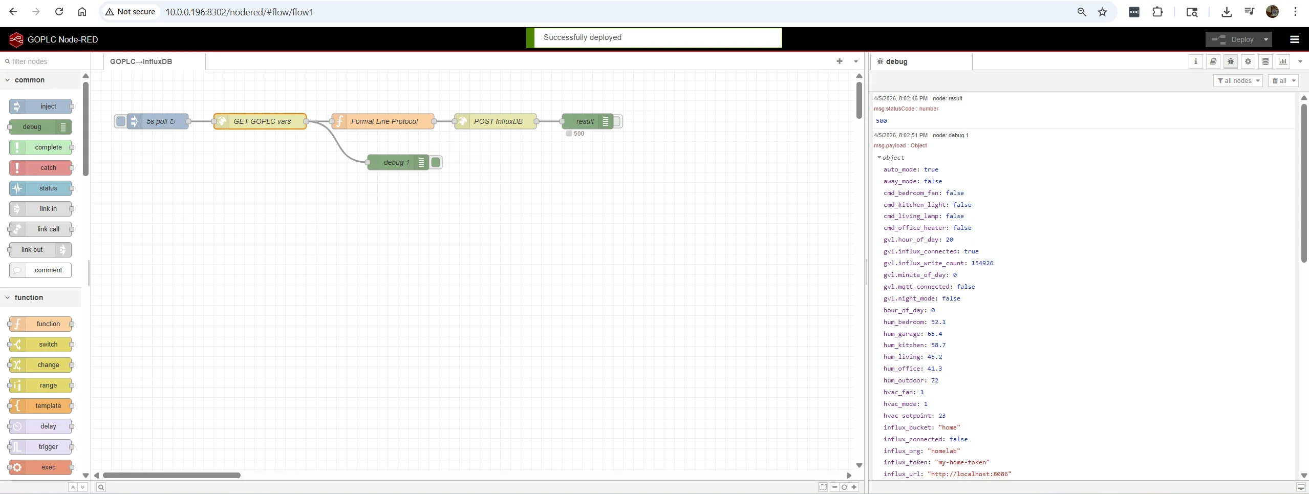 Node-RED flow polling GoPLC variables — debug panel shows live sensor data
GoPLC bundles Node-RED with Dashboard 2.0. Access at http://<pi-ip>:<port>/nodered/.
Recommended Flows
Climate Overview Panel:
[goplc-subscribe: temp_living]  → [ui_gauge: Living [temp]]
[goplc-subscribe: temp_bedroom] → [ui_gauge: Bedroom [temp]]
[goplc-subscribe: temp_kitchen] → [ui_gauge: Kitchen [temp]]
[goplc-subscribe: temp_office]  → [ui_gauge: Office [temp]]
[goplc-subscribe: temp_outdoor] → [ui_gauge: Outdoor [temp]]
[goplc-subscribe: temp_garage]  → [ui_gauge: Garage [temp]]
Device Control Panel:
[ui_switch: Living Lamp]    → [goplc-write: cmd_living_lamp]
[ui_switch: Bedroom Fan]    → [goplc-write: cmd_bedroom_fan]
[ui_switch: Kitchen Light]  → [goplc-write: cmd_kitchen_light]
[ui_switch: Office Heater]  → [goplc-write: cmd_office_heater]
HVAC Control:
[ui_dropdown: Mode (Off/Cool/Heat/Auto)]  → [goplc-write: hvac_mode]
[ui_slider: Setpoint 16-30C]              → [goplc-write: hvac_setpoint]
[ui_dropdown: Fan (Auto/Low/Med/High)]    → [goplc-write: hvac_fan]
IR Blaster Bridge (Node-RED handles edge detection so we don’t blast IR every scan):
[goplc-subscribe: hvac_json] → [rbe: block unless changed] → [mqtt out: cmnd/ir_blaster/irhvac]Trend Charts:
[goplc-subscribe: temp_living]  → [ui_chart: 24h Temperature Trend]
[goplc-subscribe: temp_outdoor] → [ui_chart: 24h Temperature Trend]
Grafana Dashboards
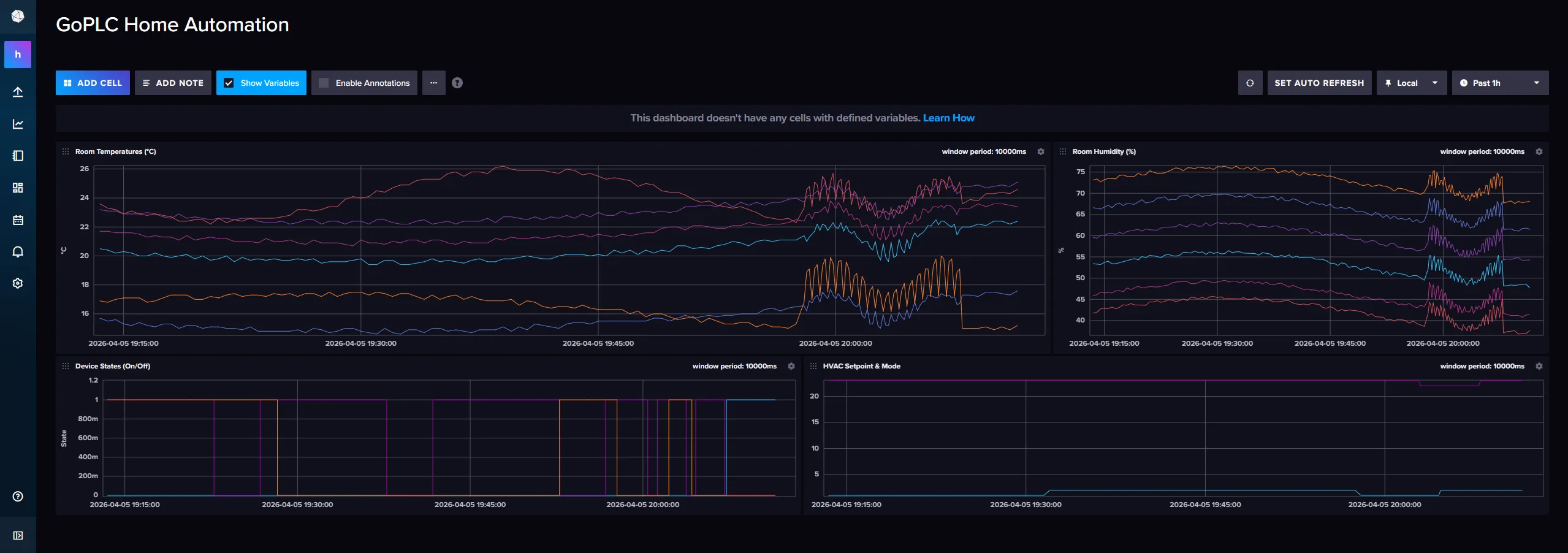 InfluxDB dashboard — room temperatures, humidity, device states, and HVAC trends
Connect Grafana to InfluxDB and create dashboards with Flux queries.
Example: Room Temperature Comparison (last 24 hours)
from(bucket: "home")
  |> range(start: -24h)
  |> filter(fn: (r) => r._measurement == "climate")
  |> filter(fn: (r) => r._field == "temperature")
  |> aggregateWindow(every: 5m, fn: mean, createEmpty: false)
Example: Device Runtime per Day
from(bucket: "home")
  |> range(start: -7d)
  |> filter(fn: (r) => r._measurement == "devices")
  |> filter(fn: (r) => r._field == "state")
  |> aggregateWindow(every: 1d, fn: mean, createEmpty: false)
  |> map(fn: (r) => ({r with _value: r._value * 24.0}))
Recommended Dashboard Panels
| Panel | Type | Query |
|---|---|---|
| Room temperatures | Time series (6 lines) | climate, field=temperature, group by room |
| Room humidity | Time series (6 lines) | climate, field=humidity, group by room |
| Current temps | Stat (6 values) | climate, last(), group by room |
| HVAC mode | Stat | hvac, field=mode, last() |
| Device on-time | Bar chart | devices, daily mean * 24h |
| Outdoor 7-day | Time series | climate, room=outdoor, 7d range |
Expanding the Project
| Addition | What It Adds | GoPLC Functions Used |
|---|---|---|
| Water leak sensors | Floor sensors via Zigbee, alarm on detection | MQTT_SUBSCRIBE + MQTT_PUBLISH (push notification) |
| Energy monitoring | Shelly EM or CT clamp, track kWh | MQTT_GET_MESSAGE_REAL + INFLUX_BATCH_ADD |
| Irrigation control | Relay board via Modbus, schedule-based | MB_WRITE_COIL + time-of-day logic |
| Pool chemistry | pH/ORP sensors via analog input, dosing pumps | MB_READ_INPUT + PID control |
| Security cameras | Motion events from Frigate via MQTT | MQTT_SUBSCRIBE, trigger recording/lights |
| Weather forecast | HTTP API call, adjust heating/cooling proactively | HTTP_GET + JSON_GET |
| Solar/battery | Modbus to inverter, optimize self-consumption | MB_READ_HOLDING + INFLUX_BATCH_ADD |
| Presence detection | HA companion app publishes location via MQTT | MQTT_GET_MESSAGE, set away_mode |
| Garage door | Shelly 1 relay + reed switch, open/close/status | MQTT_PUBLISH + MQTT_SUBSCRIBE |
| Doorbell | ESP32-CAM + MQTT, snapshot + push notification | MQTT_SUBSCRIBE + HTTP_POST (webhook) |
GoPLC Built-in MQTT Broker (Optional)
Instead of running a separate Mosquitto container, GoPLC can run its own MQTT broker directly from ST code:
(* Create and start a broker on port 1883 *)
MQTT_BROKER_CREATE('local_broker', 1883);
MQTT_BROKER_START('local_broker');

(* Check status *)
IF MQTT_BROKER_IS_RUNNING('local_broker') THEN
    (* Broker is serving clients *)
END_IF;

(* Monitor connected clients *)
clients := MQTT_BROKER_CLIENTS('local_broker');
stats   := MQTT_BROKER_STATS('local_broker');
Then point all devices, Home Assistant, and GoPLC’s own MQTT client at tcp://<pi-ip>:1883.
One fewer container to manage.
ST Function Reference (Used in This Guide)
| Function | Signature | Purpose |
|---|---|---|
MQTT_CLIENT_CREATE | (name, broker, clientID) | Create MQTT client |
MQTT_CLIENT_CREATE_AUTH | (name, broker, clientID, user, pass) | Create with auth |
MQTT_CLIENT_CONNECT | (name) | Connect to broker |
MQTT_CLIENT_IS_CONNECTED | (name) -> BOOL | Check connection |
MQTT_PUBLISH | (name, topic, payload) | Publish message |
MQTT_PUBLISH_RETAINED | (name, topic, payload) | Publish with retain flag |
MQTT_SUBSCRIBE | (name, topic) | Subscribe to topic |
MQTT_HAS_MESSAGE | (name, topic) -> BOOL | Check for new message |
MQTT_GET_MESSAGE | (name, topic) -> STRING | Get last message payload |
MQTT_GET_MESSAGE_REAL | (name, topic) -> REAL | Get as float |
MQTT_GET_MESSAGE_INT | (name, topic) -> INT | Get as integer |
MQTT_GET_MESSAGE_BOOL | (name, topic) -> BOOL | Get as boolean |
MQTT_BROKER_CREATE | (name, port) | Create built-in broker |
MQTT_BROKER_START | (name) | Start broker |
INFLUX_CONNECT | (name, url, org, bucket, token) | Connect InfluxDB v2 |
INFLUX_IS_CONNECTED | (name) -> BOOL | Check connection |
INFLUX_BATCH_ADD | (name, measurement, tags, field, value) | Buffer a REAL point |
INFLUX_BATCH_ADD_INT | (name, measurement, tags, field, value) | Buffer an INT point |
INFLUX_BATCH_FLUSH | (name) -> DINT | Flush buffer, return count |
INFLUX_WRITE | (name, measurement, tags, field, value) | Write single REAL point |
GoPLC Smart Washing Machine Controller
Why GoPLC for Appliance Control?
A modern washing machine controller is just a small PLC: it sequences valves, motors, and pumps based on sensor inputs, runs safety interlocks, and follows a state machine. Factory boards are expensive, proprietary, and non-repairable. GoPLC gives you:
- Full control over every cycle parameter — wash time, spin speed, water level, temperature
- Phone dashboard via Node-RED — start/stop, cycle selection, status, push notifications
- Real industrial I/O — Waveshare DIN-rail Modbus modules rated for 10A 250VAC relays
- State machine in Structured Text — readable, modifiable, no black-box firmware
- Expandable — add sensors, logging, energy monitoring, or integrate with home automation
System Architecture
                                    RS485 Bus (daisy-chain)
                                   ┌──────────────────────────────┐
  ┌──────────────┐   Ethernet      │                              │
  │ Raspberry Pi │──────────────►┌─┴──────────────┐  ┌───────────┴────────────┐
  │   + GoPLC    │  Modbus TCP   │ Waveshare      │  │ Waveshare              │
  │              │               │ RS485-to-ETH   │  │ Modbus RTU Analog      │
  │  Node-RED    │               │ Gateway        │  │ Input 8CH              │
  │  Dashboard   │               └─┬──────────────┘  │ (Slave ID 2)           │
  └──────────────┘                 │                  │ - Water temperature    │
         │                         │                  │ - Motor current        │
      WiFi/LAN                  ┌──┴──────────────┐   │ - Water pressure/level │
         │                      │ Waveshare       │  └────────────────────────┘
    ┌────┴─────┐                │ Modbus RTU      │
    │  Phone   │                │ Relay (D)       │
    │Dashboard │                │ (Slave ID 1)    │
    └──────────┘                │ 8 Relay + 8 DI  │
                                └─────────────────┘
                                       │
                            ┌──────────┴──────────┐
                            │  Washing Machine    │
                            │  Valves, Motor,     │
                            │  Pump, Door Lock,   │
                            │  Sensors            │
                            └─────────────────────┘
Data flow: GoPLC runs the wash cycle state machine in Structured Text. Each scan (100ms), it reads sensors via Modbus TCP through the Waveshare gateway, runs control logic, and writes relay outputs. Node-RED provides the operator interface on any browser.
Bill of Materials
| # | Item | Purpose | Est. Cost |
|---|---|---|---|
| 1 | Raspberry Pi 2/3/4/5 | Runs GoPLC + Node-RED | $35-80 |
| 2 | MicroSD card (32GB+) | Pi OS + GoPLC | $8 |
| 3 | Waveshare RS485 TO ETH (B) | Modbus TCP-to-RTU gateway | $20 |
| 4 | Waveshare Modbus RTU Relay (D) | 8 relay outputs + 8 digital inputs | $35 |
| 5 | Waveshare Modbus RTU Analog Input 8CH | Analog sensor inputs (12-bit) | $30 |
| 6 | DIN rail power supply 120VAC to 24VDC (60W) | Powers all Modbus modules + sensors | $15 |
| 7 | DIN rail circuit breaker 15A | Branch protection for 120VAC loads | $8 |
| 8 | DIN rail terminal blocks (20-pack) | All point-to-point wiring connections | $12 |
| 9 | 35mm DIN rail (1 meter) | Mounting for all DIN components | $6 |
| 10 | Enclosure (IP54 or better) | Houses all control components | $25-40 |
| 11 | 18 AWG stranded wire (assorted colors) | 120VAC load wiring | $15 |
| 12 | 22 AWG stranded wire (assorted colors) | 24VDC signal/sensor wiring | $10 |
| 13 | Wire ferrules + crimp tool | Clean terminal connections | $20 |
| 14 | Ethernet cable (Cat5e, length as needed) | Pi to RS485-to-ETH gateway | $5 |
| Total (approx.) | $245-305 |
About the Waveshare Modules
RS485 TO ETH (B) — Bridges Modbus TCP (Ethernet) to Modbus RTU (RS485). Configure it in “Modbus TCP to RTU gateway” mode. GoPLC talks standard Modbus TCP; the gateway handles serial framing and timing on the RS485 side. Supports 9-24V power, DIN rail mount.
Modbus RTU Relay (D) — 8 relay outputs (10A 250VAC each) + 8 optocoupled digital inputs. 7-36V power. DIN rail mount. Default: slave 1, 9600 baud, 8N1.
Modbus RTU Analog Input 8CH — 8 channels, 12-bit resolution. Configurable per-channel: 0-10V, 2-10V, 0-20mA, or 4-20mA. 7-36V power. DIN rail mount. Default: slave 1 (must be changed to slave 2 before connecting to the bus).
I/O Assignment
Relay (D) Module — Slave ID 1
Relay Outputs (Coils 0x0000-0x0007)
| Relay | Coil Addr | Function | Load | Notes |
|---|---|---|---|---|
| CH1 | 0x0000 | Hot water inlet valve | 120VAC solenoid | Normally closed valve |
| CH2 | 0x0001 | Cold water inlet valve | 120VAC solenoid | Normally closed valve |
| CH3 | 0x0002 | Drain pump | 120VAC motor | ~1A typical |
| CH4 | 0x0003 | Door lock solenoid | 24VDC solenoid | Energize to lock |
| CH5 | 0x0004 | Motor - agitate | 120VAC contactor coil | Low speed, reversing |
| CH6 | 0x0005 | Motor - spin | 120VAC contactor coil | High speed, one direction |
| CH7 | 0x0006 | Buzzer | 24VDC buzzer | Cycle complete alert |
| CH8 | 0x0007 | Spare | — | Future: fabric softener valve |
Digital Inputs (Discrete Inputs 0x0000-0x0007)
| Input | Addr | Function | Type | Notes |
|---|---|---|---|---|
| DI1 | 0x0000 | Door closed | N.O. switch | TRUE = door closed |
| DI2 | 0x0001 | Door locked feedback | N.O. contact | TRUE = lock engaged |
| DI3 | 0x0002 | Water level - low | Pressure switch | TRUE = above minimum |
| DI4 | 0x0003 | Water level - medium | Pressure switch | TRUE = medium fill |
| DI5 | 0x0004 | Water level - high | Pressure switch | TRUE = full |
| DI6 | 0x0005 | Motor overload trip | N.C. thermal OL | FALSE = tripped |
| DI7 | 0x0006 | Water leak detected | Leak sensor | TRUE = leak |
| DI8 | 0x0007 | Spare | — | — |
Analog Input Module — Slave ID 2
| Channel | Reg Addr | Function | Range | Sensor |
|---|---|---|---|---|
| CH1 | 0x0000 | Water temperature | 4-20mA | PT100 transmitter (0-100C) |
| CH2 | 0x0001 | Motor current | 0-10V | Split-core CT + signal conditioner |
| CH3 | 0x0002 | Vibration | 0-10V | Accelerometer module |
| CH4-8 | 0x0003-0x0007 | Spare | — | — |
Wiring — Point to Point
Power Distribution
| From | To | Wire | Notes |
|---|---|---|---|
| Mains 120VAC Hot | CB-15A input | 14 AWG black | House breaker should also protect this circuit |
| CB-15A output | Terminal TB-HOT | 14 AWG black | Fused 120VAC hot bus |
| Mains 120VAC Neutral | Terminal TB-NEU | 14 AWG white | Neutral bus |
| Mains Ground | Terminal TB-GND | 14 AWG green | Ground bus, bond to enclosure |
| TB-HOT | 24VDC PSU L input | 18 AWG black | PSU line input |
| TB-NEU | 24VDC PSU N input | 18 AWG white | PSU neutral input |
| TB-GND | 24VDC PSU GND input | 18 AWG green | PSU earth ground |
| 24VDC PSU +V out | Terminal TB-24V+ | 18 AWG red | 24VDC positive bus |
| 24VDC PSU -V out | Terminal TB-24V- | 18 AWG blue | 24VDC negative bus (0V) |
| TB-24V+ | Relay (D) V+ | 22 AWG red | Module power |
| TB-24V- | Relay (D) V- | 22 AWG blue | Module power |
| TB-24V+ | Analog Input V+ | 22 AWG red | Module power |
| TB-24V- | Analog Input V- | 22 AWG blue | Module power |
| TB-24V+ | RS485-to-ETH V+ | 22 AWG red | Gateway power (9-24V) |
| TB-24V- | RS485-to-ETH V- | 22 AWG blue | Gateway power |
RS485 Bus (Daisy-Chain)
| From | To | Wire | Notes |
|---|---|---|---|
| RS485-to-ETH A+ | Relay (D) A | 22 AWG twisted pair | Use shielded twisted pair |
| RS485-to-ETH B- | Relay (D) B | 22 AWG twisted pair | Same pair |
| Relay (D) A | Analog Input A | 22 AWG twisted pair | Continue daisy chain |
| Relay (D) B | Analog Input B | 22 AWG twisted pair | Same pair |
| Analog Input A-B | 120 ohm resistor | — | Termination at last device on bus |
| Cable shield | TB-GND | — | Ground shield at one end only |
Ethernet
| From | To | Wire | Notes |
|---|---|---|---|
| Pi Ethernet port | RS485-to-ETH RJ45 | Cat5e patch cable | Standard Ethernet |
Relay Outputs to Loads
| From | To | Wire | Notes |
|---|---|---|---|
| TB-HOT | Relay CH1 COM | 18 AWG black | Hot water valve circuit |
| Relay CH1 N.O. | Hot water valve | 18 AWG black | Valve other wire to TB-NEU |
| TB-HOT | Relay CH2 COM | 18 AWG black | Cold water valve circuit |
| Relay CH2 N.O. | Cold water valve | 18 AWG black | Valve other wire to TB-NEU |
| TB-HOT | Relay CH3 COM | 18 AWG black | Drain pump circuit |
| Relay CH3 N.O. | Drain pump | 18 AWG black | Pump other wire to TB-NEU |
| TB-24V+ | Relay CH4 COM | 22 AWG red | Door lock circuit (24VDC) |
| Relay CH4 N.O. | Door lock solenoid + | 22 AWG red | Solenoid - to TB-24V- |
| TB-HOT | Relay CH5 COM | 18 AWG black | Motor agitate contactor |
| Relay CH5 N.O. | Agitate contactor coil | 18 AWG black | Coil other side to TB-NEU |
| TB-HOT | Relay CH6 COM | 18 AWG black | Motor spin contactor |
| Relay CH6 N.O. | Spin contactor coil | 18 AWG black | Coil other side to TB-NEU |
| TB-24V+ | Relay CH7 COM | 22 AWG red | Buzzer circuit (24VDC) |
| Relay CH7 N.O. | Buzzer + | 22 AWG red | Buzzer - to TB-24V- |
Digital Inputs
The Relay (D) module supports passive (dry contact) and active (wet contact) inputs. Wire all inputs as dry contacts with the module’s internal pull-up:
| From | To | Wire | Notes |
|---|---|---|---|
| Relay (D) DI1 | Door closed switch N.O. | 22 AWG | Switch other terminal to DI COM |
| Relay (D) DI2 | Door lock feedback N.O. | 22 AWG | Contact other terminal to DI COM |
| Relay (D) DI3 | Level switch - low | 22 AWG | Closes at low water level |
| Relay (D) DI4 | Level switch - medium | 22 AWG | Closes at medium level |
| Relay (D) DI5 | Level switch - high | 22 AWG | Closes at high level |
| Relay (D) DI6 | Motor thermal O/L N.C. | 22 AWG | Opens on overload trip |
| Relay (D) DI7 | Leak sensor N.O. | 22 AWG | Closes on water detection |
| DI COM (all) | TB-24V- | 22 AWG | Common return for all DIs |
Analog Inputs
| From | To | Wire | Notes |
|---|---|---|---|
| TB-24V+ | PT100 transmitter + | 22 AWG red | Loop power for 4-20mA |
| PT100 transmitter signal | Analog CH1 + | 22 AWG | 4-20mA signal |
| Analog CH1 - | TB-24V- | 22 AWG blue | Return |
| Motor CT signal + | Analog CH2 + | 22 AWG | 0-10V from CT conditioner |
| Motor CT signal - | Analog CH2 - | 22 AWG | Signal ground |
| Vibration sensor + | Analog CH3 + | 22 AWG | 0-10V from accelerometer |
| Vibration sensor - | Analog CH3 - | 22 AWG | Signal ground |
Waveshare Gateway Configuration
Before connecting, configure the RS485-to-ETH gateway via its web interface (default IP: 192.168.1.200):
- Set a static IP on your network (e.g., 192.168.1.100)
- Mode: Modbus TCP to RTU
- Serial: 9600 baud, 8N1 (matches Waveshare module defaults)
- TCP port: 502 (standard Modbus TCP port)
Also set the Analog Input module slave address to 2 (default is 1, same as the Relay module — they must be different). Use the module’s configuration software or send the Modbus command to write holding register 0x4000 with value 0x0002.
GoPLC Configuration
Project File Setup
Create a new GoPLC project or add to an existing one. The washer needs two tasks:
- wash_main — Cycle state machine, I/O scanning, interlocks (100ms scan)
- wash_monitor — Analog scaling, trending, diagnostics (500ms scan)
YAML Task Configuration
tasks:
  - name: wash_main
    program: POU_WashMain
    scan_time_ms: 100
  - name: wash_monitor
    program: POU_WashMonitor
    scan_time_ms: 500
ST Programs
GVL — Global Variables
VAR_GLOBAL
    (* --- Modbus Connection --- *)
    gw_ip           : STRING := '192.168.1.100';  (* RS485-to-ETH gateway IP *)
    gw_port         : INT := 502;
    mb_connected     : BOOL := FALSE;

    (* --- Relay Outputs (coil addresses) --- *)
    COIL_HOT_VALVE   : INT := 0;   (* CH1 *)
    COIL_COLD_VALVE  : INT := 1;   (* CH2 *)
    COIL_DRAIN_PUMP  : INT := 2;   (* CH3 *)
    COIL_DOOR_LOCK   : INT := 3;   (* CH4 *)
    COIL_MOTOR_AGIT  : INT := 4;   (* CH5 *)
    COIL_MOTOR_SPIN  : INT := 5;   (* CH6 *)
    COIL_BUZZER      : INT := 6;   (* CH7 *)

    (* --- Output Commands (written by state machine) --- *)
    cmd_hot_valve    : BOOL := FALSE;
    cmd_cold_valve   : BOOL := FALSE;
    cmd_drain_pump   : BOOL := FALSE;
    cmd_door_lock    : BOOL := FALSE;
    cmd_motor_agit   : BOOL := FALSE;
    cmd_motor_spin   : BOOL := FALSE;
    cmd_buzzer       : BOOL := FALSE;

    (* --- Digital Input States (read from module) --- *)
    di_door_closed   : BOOL := FALSE;
    di_door_locked   : BOOL := FALSE;
    di_level_low     : BOOL := FALSE;
    di_level_med     : BOOL := FALSE;
    di_level_high    : BOOL := FALSE;
    di_motor_ol_ok   : BOOL := TRUE;   (* N.C. — TRUE = healthy *)
    di_leak_detect   : BOOL := FALSE;

    (* --- Analog Values (scaled) --- *)
    water_temp_c     : REAL := 0.0;    (* Degrees C *)
    motor_current_a  : REAL := 0.0;    (* Amps *)
    vibration_g      : REAL := 0.0;    (* g-force *)

    (* --- Cycle Settings (set from dashboard) --- *)
    cycle_select     : INT := 0;       (* 0=none, 1=normal, 2=heavy, 3=delicate, 4=rinse_only *)
    water_temp_set   : INT := 1;       (* 0=cold, 1=warm, 2=hot *)
    water_level_set  : INT := 1;       (* 0=low, 1=medium, 2=high *)
    extra_rinse      : BOOL := FALSE;
    cmd_start        : BOOL := FALSE;  (* Start button from dashboard *)
    cmd_stop         : BOOL := FALSE;  (* Stop/cancel from dashboard *)

    (* --- Cycle Parameters (set by cycle_select) --- *)
    wash_time_s      : INT := 600;     (* Wash duration seconds *)
    rinse_time_s     : INT := 300;     (* Rinse duration seconds *)
    spin_time_s      : INT := 360;     (* Spin duration seconds *)
    agitate_on_s     : INT := 10;      (* Agitate on-time per stroke *)
    agitate_off_s    : INT := 3;       (* Pause between strokes *)

    (* --- State Machine --- *)
    wash_state       : INT := 0;       (* Current state *)
    state_timer      : DINT := 0;      (* Seconds in current state *)
    cycle_active     : BOOL := FALSE;
    fault_code       : INT := 0;       (* 0=none, see fault list *)
    fault_active     : BOOL := FALSE;

    (* --- State Constants --- *)
    ST_IDLE          : INT := 0;
    ST_DOOR_LOCK     : INT := 1;
    ST_FILL_WASH     : INT := 2;
    ST_HEAT_WAIT     : INT := 3;
    ST_AGITATE       : INT := 4;
    ST_DRAIN_1       : INT := 5;
    ST_FILL_RINSE    : INT := 6;
    ST_RINSE         : INT := 7;
    ST_DRAIN_2       : INT := 8;
    ST_SPIN          : INT := 9;
    ST_DRAIN_FINAL   : INT := 10;
    ST_COMPLETE      : INT := 11;
    ST_FAULT         : INT := 99;

    (* --- Fault Codes --- *)
    FLT_NONE         : INT := 0;
    FLT_DOOR_OPEN    : INT := 1;
    FLT_DOOR_LOCK    : INT := 2;   (* Lock didn't engage in time *)
    FLT_FILL_TIMEOUT : INT := 3;   (* Didn't reach level in 5 min *)
    FLT_MOTOR_OL     : INT := 4;   (* Motor thermal overload *)
    FLT_LEAK         : INT := 5;   (* Water leak detected *)
    FLT_UNBALANCE    : INT := 6;   (* Excessive vibration in spin *)
    FLT_TEMP_HIGH    : INT := 7;   (* Water over-temperature *)
    FLT_COMM_LOSS    : INT := 8;   (* Modbus communication lost *)

    (* --- Diagnostics --- *)
    total_cycles     : DINT := 0;
    scan_counter     : DINT := 0;
    agitate_toggle   : BOOL := FALSE;  (* Alternates for agitate stroke *)
    agitate_timer    : DINT := 0;
    spin_ramp_done   : BOOL := FALSE;
    rinse_count      : INT := 0;       (* Tracks rinse passes *)
END_VAR
POU_WashMain — Main Cycle Controller
PROGRAM POU_WashMain
VAR
    mb_init_done   : BOOL := FALSE;
    prev_second    : DINT := 0;
    now_ms         : DINT;
    now_s          : DINT;
    coil_states    : ARRAY[0..7] OF BOOL;
    di_values      : ARRAY[0..7] OF BOOL;
    target_level   : BOOL;
END_VAR

(* ============================================================
   SECTION 1: MODBUS INITIALIZATION
   Create and connect the Modbus TCP client once.
   ============================================================ *)
IF NOT mb_init_done THEN
    MB_CLIENT_CREATE('washer', GVL.gw_ip, GVL.gw_port, 1);
    MB_CLIENT_CONNECT('washer');
    mb_init_done := TRUE;
END_IF;

GVL.mb_connected := MB_CLIENT_CONNECTED('washer');

(* Reconnect if we lose connection *)
IF mb_init_done AND NOT GVL.mb_connected THEN
    MB_CLIENT_CONNECT('washer');
END_IF;

(* ============================================================
   SECTION 2: READ INPUTS
   Read digital inputs and map to GVL booleans.
   ============================================================ *)
IF GVL.mb_connected THEN
    (* Read 8 discrete inputs from slave 1, starting at address 0 *)
    di_values := MB_READ_DISCRETE('washer', 0, 8);

    GVL.di_door_closed := di_values[0];
    GVL.di_door_locked := di_values[1];
    GVL.di_level_low   := di_values[2];
    GVL.di_level_med   := di_values[3];
    GVL.di_level_high  := di_values[4];
    GVL.di_motor_ol_ok := di_values[5];   (* N.C. — TRUE = healthy *)
    GVL.di_leak_detect := di_values[6];
END_IF;

(* ============================================================
   SECTION 3: TIMEKEEPING
   Increment state_timer once per second.
   ============================================================ *)
now_ms := NOW_MS();
now_s  := now_ms / 1000;
IF now_s <> prev_second THEN
    prev_second := now_s;
    GVL.state_timer := GVL.state_timer + 1;
    GVL.scan_counter := GVL.scan_counter + 1;
END_IF;

(* ============================================================
   SECTION 4: SAFETY INTERLOCKS
   These override everything — checked every scan.
   ============================================================ *)

(* Leak detection — immediate shutdown *)
IF GVL.di_leak_detect THEN
    GVL.fault_code := GVL.FLT_LEAK;
    GVL.fault_active := TRUE;
    GVL.wash_state := GVL.ST_FAULT;
END_IF;

(* Motor overload — stop motor immediately *)
IF NOT GVL.di_motor_ol_ok THEN
    GVL.cmd_motor_agit := FALSE;
    GVL.cmd_motor_spin := FALSE;
    GVL.fault_code := GVL.FLT_MOTOR_OL;
    GVL.fault_active := TRUE;
    GVL.wash_state := GVL.ST_FAULT;
END_IF;

(* Over-temperature — stop heating (close hot valve) *)
IF GVL.water_temp_c > 85.0 THEN
    GVL.cmd_hot_valve := FALSE;
    GVL.fault_code := GVL.FLT_TEMP_HIGH;
    GVL.fault_active := TRUE;
    GVL.wash_state := GVL.ST_FAULT;
END_IF;

(* Communication loss — if active cycle, go to fault *)
IF GVL.cycle_active AND NOT GVL.mb_connected THEN
    GVL.fault_code := GVL.FLT_COMM_LOSS;
    GVL.fault_active := TRUE;
    GVL.wash_state := GVL.ST_FAULT;
END_IF;

(* Stop button — drain and unlock *)
IF GVL.cmd_stop AND GVL.cycle_active THEN
    GVL.cmd_stop := FALSE;
    GVL.cmd_hot_valve := FALSE;
    GVL.cmd_cold_valve := FALSE;
    GVL.cmd_motor_agit := FALSE;
    GVL.cmd_motor_spin := FALSE;
    GVL.cmd_drain_pump := TRUE;
    GVL.wash_state := GVL.ST_DRAIN_FINAL;
    GVL.state_timer := 0;
END_IF;

(* ============================================================
   SECTION 5: CYCLE PARAMETER SELECTION
   Set wash/rinse/spin times based on cycle_select.
   ============================================================ *)
CASE GVL.cycle_select OF
    1: (* Normal *)
        GVL.wash_time_s := 600;
        GVL.rinse_time_s := 300;
        GVL.spin_time_s := 360;
        GVL.agitate_on_s := 10;
        GVL.agitate_off_s := 3;
    2: (* Heavy Duty *)
        GVL.wash_time_s := 900;
        GVL.rinse_time_s := 420;
        GVL.spin_time_s := 480;
        GVL.agitate_on_s := 12;
        GVL.agitate_off_s := 2;
    3: (* Delicate *)
        GVL.wash_time_s := 360;
        GVL.rinse_time_s := 240;
        GVL.spin_time_s := 180;
        GVL.agitate_on_s := 6;
        GVL.agitate_off_s := 5;
    4: (* Rinse Only *)
        GVL.wash_time_s := 0;
        GVL.rinse_time_s := 300;
        GVL.spin_time_s := 360;
        GVL.agitate_on_s := 8;
        GVL.agitate_off_s := 3;
END_CASE;

(* ============================================================
   SECTION 6: MAIN STATE MACHINE
   ============================================================ *)
CASE GVL.wash_state OF

    (* ---- IDLE: Waiting for start command ---- *)
    0: (* ST_IDLE *)
        GVL.cycle_active := FALSE;
        GVL.cmd_hot_valve := FALSE;
        GVL.cmd_cold_valve := FALSE;
        GVL.cmd_drain_pump := FALSE;
        GVL.cmd_door_lock := FALSE;
        GVL.cmd_motor_agit := FALSE;
        GVL.cmd_motor_spin := FALSE;
        GVL.cmd_buzzer := FALSE;

        IF GVL.cmd_start AND GVL.di_door_closed AND GVL.cycle_select > 0 THEN
            GVL.cmd_start := FALSE;
            GVL.fault_code := GVL.FLT_NONE;
            GVL.fault_active := FALSE;
            GVL.rinse_count := 0;
            GVL.cycle_active := TRUE;
            GVL.state_timer := 0;

            (* Rinse-only skips to fill_rinse *)
            IF GVL.cycle_select = 4 THEN
                GVL.wash_state := GVL.ST_DOOR_LOCK;
            ELSE
                GVL.wash_state := GVL.ST_DOOR_LOCK;
            END_IF;
        END_IF;

    (* ---- DOOR LOCK: Engage lock, verify feedback ---- *)
    1: (* ST_DOOR_LOCK *)
        GVL.cmd_door_lock := TRUE;

        IF GVL.di_door_locked THEN
            GVL.state_timer := 0;
            IF GVL.cycle_select = 4 THEN
                GVL.wash_state := GVL.ST_FILL_RINSE;
            ELSE
                GVL.wash_state := GVL.ST_FILL_WASH;
            END_IF;
        ELSIF GVL.state_timer > 5 THEN
            (* Lock didn't engage in 5 seconds *)
            GVL.fault_code := GVL.FLT_DOOR_LOCK;
            GVL.fault_active := TRUE;
            GVL.wash_state := GVL.ST_FAULT;
        END_IF;

    (* ---- FILL WASH: Open valve(s) until target level ---- *)
    2: (* ST_FILL_WASH *)
        (* Select valve based on temperature setting *)
        CASE GVL.water_temp_set OF
            0: (* Cold *)
                GVL.cmd_hot_valve := FALSE;
                GVL.cmd_cold_valve := TRUE;
            1: (* Warm — both valves *)
                GVL.cmd_hot_valve := TRUE;
                GVL.cmd_cold_valve := TRUE;
            2: (* Hot *)
                GVL.cmd_hot_valve := TRUE;
                GVL.cmd_cold_valve := FALSE;
        END_CASE;

        (* Check target level reached *)
        CASE GVL.water_level_set OF
            0: target_level := GVL.di_level_low;
            1: target_level := GVL.di_level_med;
            2: target_level := GVL.di_level_high;
        END_CASE;

        IF target_level THEN
            GVL.cmd_hot_valve := FALSE;
            GVL.cmd_cold_valve := FALSE;
            GVL.state_timer := 0;

            (* If hot or warm, wait for temperature *)
            IF GVL.water_temp_set > 0 THEN
                GVL.wash_state := GVL.ST_HEAT_WAIT;
            ELSE
                GVL.wash_state := GVL.ST_AGITATE;
            END_IF;
        ELSIF GVL.state_timer > 300 THEN
            (* 5 minute fill timeout *)
            GVL.cmd_hot_valve := FALSE;
            GVL.cmd_cold_valve := FALSE;
            GVL.fault_code := GVL.FLT_FILL_TIMEOUT;
            GVL.fault_active := TRUE;
            GVL.wash_state := GVL.ST_FAULT;
        END_IF;

    (* ---- HEAT WAIT: Let hot water stabilize (no heater element) ---- *)
    3: (* ST_HEAT_WAIT *)
        (* No electric heater — just using hot water supply.
           Wait 30 seconds for mixing, then proceed. *)
        IF GVL.state_timer > 30 THEN
            GVL.state_timer := 0;
            GVL.wash_state := GVL.ST_AGITATE;
        END_IF;

    (* ---- AGITATE: Motor on/off strokes for wash time ---- *)
    4: (* ST_AGITATE *)
        GVL.agitate_timer := GVL.agitate_timer + 1;

        IF GVL.agitate_toggle THEN
            (* Motor ON phase *)
            GVL.cmd_motor_agit := TRUE;
            IF GVL.agitate_timer >= GVL.agitate_on_s THEN
                GVL.agitate_timer := 0;
                GVL.agitate_toggle := FALSE;
                GVL.cmd_motor_agit := FALSE;
            END_IF;
        ELSE
            (* Pause phase *)
            GVL.cmd_motor_agit := FALSE;
            IF GVL.agitate_timer >= GVL.agitate_off_s THEN
                GVL.agitate_timer := 0;
                GVL.agitate_toggle := TRUE;
            END_IF;
        END_IF;

        (* Check if wash time complete *)
        IF GVL.state_timer >= GVL.wash_time_s THEN
            GVL.cmd_motor_agit := FALSE;
            GVL.agitate_timer := 0;
            GVL.state_timer := 0;
            GVL.wash_state := GVL.ST_DRAIN_1;
        END_IF;

    (* ---- DRAIN 1: Drain wash water ---- *)
    5: (* ST_DRAIN_1 *)
        GVL.cmd_drain_pump := TRUE;

        (* Drain until below low level, plus 30s extra *)
        IF NOT GVL.di_level_low AND GVL.state_timer > 30 THEN
            GVL.cmd_drain_pump := FALSE;
            GVL.state_timer := 0;
            GVL.wash_state := GVL.ST_FILL_RINSE;
        ELSIF GVL.state_timer > 180 THEN
            (* 3 minute drain timeout — pump may be clogged but continue *)
            GVL.cmd_drain_pump := FALSE;
            GVL.state_timer := 0;
            GVL.wash_state := GVL.ST_FILL_RINSE;
        END_IF;

    (* ---- FILL RINSE: Fill with cold water ---- *)
    6: (* ST_FILL_RINSE *)
        GVL.cmd_hot_valve := FALSE;
        GVL.cmd_cold_valve := TRUE;

        CASE GVL.water_level_set OF
            0: target_level := GVL.di_level_low;
            1: target_level := GVL.di_level_med;
            2: target_level := GVL.di_level_high;
        END_CASE;

        IF target_level THEN
            GVL.cmd_cold_valve := FALSE;
            GVL.state_timer := 0;
            GVL.wash_state := GVL.ST_RINSE;
        ELSIF GVL.state_timer > 300 THEN
            GVL.cmd_cold_valve := FALSE;
            GVL.fault_code := GVL.FLT_FILL_TIMEOUT;
            GVL.fault_active := TRUE;
            GVL.wash_state := GVL.ST_FAULT;
        END_IF;

    (* ---- RINSE: Agitate in clean water ---- *)
    7: (* ST_RINSE *)
        GVL.agitate_timer := GVL.agitate_timer + 1;

        IF GVL.agitate_toggle THEN
            GVL.cmd_motor_agit := TRUE;
            IF GVL.agitate_timer >= GVL.agitate_on_s THEN
                GVL.agitate_timer := 0;
                GVL.agitate_toggle := FALSE;
                GVL.cmd_motor_agit := FALSE;
            END_IF;
        ELSE
            GVL.cmd_motor_agit := FALSE;
            IF GVL.agitate_timer >= GVL.agitate_off_s THEN
                GVL.agitate_timer := 0;
                GVL.agitate_toggle := TRUE;
            END_IF;
        END_IF;

        IF GVL.state_timer >= GVL.rinse_time_s THEN
            GVL.cmd_motor_agit := FALSE;
            GVL.agitate_timer := 0;
            GVL.state_timer := 0;
            GVL.rinse_count := GVL.rinse_count + 1;
            GVL.wash_state := GVL.ST_DRAIN_2;
        END_IF;

    (* ---- DRAIN 2: Drain rinse water ---- *)
    8: (* ST_DRAIN_2 *)
        GVL.cmd_drain_pump := TRUE;

        IF NOT GVL.di_level_low AND GVL.state_timer > 30 THEN
            GVL.cmd_drain_pump := FALSE;
            GVL.state_timer := 0;

            (* Extra rinse? Do another rinse pass *)
            IF GVL.extra_rinse AND GVL.rinse_count < 2 THEN
                GVL.wash_state := GVL.ST_FILL_RINSE;
            ELSE
                GVL.wash_state := GVL.ST_SPIN;
            END_IF;
        ELSIF GVL.state_timer > 180 THEN
            GVL.cmd_drain_pump := FALSE;
            GVL.state_timer := 0;
            GVL.wash_state := GVL.ST_SPIN;
        END_IF;

    (* ---- SPIN: High-speed spin to extract water ---- *)
    9: (* ST_SPIN *)
        GVL.cmd_drain_pump := TRUE;   (* Keep draining during spin *)
        GVL.cmd_motor_spin := TRUE;

        (* Unbalance detection via vibration sensor *)
        IF GVL.vibration_g > 2.5 THEN
            (* Excessive vibration — stop spin, redistribute, retry *)
            GVL.cmd_motor_spin := FALSE;
            GVL.fault_code := GVL.FLT_UNBALANCE;
            GVL.fault_active := TRUE;
            GVL.wash_state := GVL.ST_FAULT;
        END_IF;

        IF GVL.state_timer >= GVL.spin_time_s THEN
            GVL.cmd_motor_spin := FALSE;
            GVL.cmd_drain_pump := FALSE;
            GVL.state_timer := 0;
            GVL.wash_state := GVL.ST_DRAIN_FINAL;
        END_IF;

    (* ---- DRAIN FINAL: Final drain after spin ---- *)
    10: (* ST_DRAIN_FINAL *)
        GVL.cmd_motor_agit := FALSE;
        GVL.cmd_motor_spin := FALSE;
        GVL.cmd_drain_pump := TRUE;

        IF GVL.state_timer > 15 THEN
            GVL.cmd_drain_pump := FALSE;
            GVL.state_timer := 0;
            GVL.wash_state := GVL.ST_COMPLETE;
        END_IF;

    (* ---- COMPLETE: Unlock door, signal done ---- *)
    11: (* ST_COMPLETE *)
        GVL.cmd_door_lock := FALSE;
        GVL.cmd_buzzer := TRUE;
        GVL.total_cycles := GVL.total_cycles + 1;

        (* Buzzer for 10 seconds, then silence *)
        IF GVL.state_timer > 10 THEN
            GVL.cmd_buzzer := FALSE;
        END_IF;

        (* Wait for door to open, then return to idle *)
        IF NOT GVL.di_door_closed THEN
            GVL.cmd_buzzer := FALSE;
            GVL.cycle_active := FALSE;
            GVL.wash_state := GVL.ST_IDLE;
        END_IF;

    (* ---- FAULT: Safe state ---- *)
    99: (* ST_FAULT *)
        GVL.cmd_motor_agit := FALSE;
        GVL.cmd_motor_spin := FALSE;
        GVL.cmd_hot_valve := FALSE;
        GVL.cmd_cold_valve := FALSE;
        (* Keep drain pump ON in fault to empty tub *)
        GVL.cmd_drain_pump := TRUE;
        GVL.cmd_buzzer := TRUE;
        GVL.cycle_active := FALSE;

        (* After 60 seconds draining, unlock door *)
        IF GVL.state_timer > 60 THEN
            GVL.cmd_drain_pump := FALSE;
            GVL.cmd_door_lock := FALSE;
            GVL.cmd_buzzer := FALSE;
        END_IF;

        (* Reset fault from dashboard — returns to idle *)
        IF GVL.cmd_start AND NOT GVL.cycle_active THEN
            GVL.cmd_start := FALSE;
            GVL.fault_code := GVL.FLT_NONE;
            GVL.fault_active := FALSE;
            GVL.wash_state := GVL.ST_IDLE;
        END_IF;

END_CASE;

(* ============================================================
   SECTION 7: WRITE OUTPUTS
   Write all coil commands to the relay module every scan.
   ============================================================ *)
IF GVL.mb_connected THEN
    coil_states[0] := GVL.cmd_hot_valve;
    coil_states[1] := GVL.cmd_cold_valve;
    coil_states[2] := GVL.cmd_drain_pump;
    coil_states[3] := GVL.cmd_door_lock;
    coil_states[4] := GVL.cmd_motor_agit;
    coil_states[5] := GVL.cmd_motor_spin;
    coil_states[6] := GVL.cmd_buzzer;
    coil_states[7] := FALSE;  (* Spare *)

    MB_WRITE_COILS('washer', 0, coil_states);
END_IF;

END_PROGRAM
POU_WashMonitor — Analog Scaling and Diagnostics
PROGRAM POU_WashMonitor
VAR
    mb_init_done : BOOL := FALSE;
    raw_values   : ARRAY[0..7] OF INT;
    raw_ch1      : INT;
    raw_ch2      : INT;
    raw_ch3      : INT;
END_VAR

(* ============================================================
   Connect to analog input module (slave ID 2)
   Uses same gateway IP but different unit ID.
   ============================================================ *)
IF NOT mb_init_done THEN
    MB_CLIENT_CREATE('washer_ai', GVL.gw_ip, GVL.gw_port, 2);
    MB_CLIENT_CONNECT('washer_ai');
    mb_init_done := TRUE;
END_IF;

(* ============================================================
   Read 3 analog input channels (input registers, FC04)
   12-bit raw values: 0-4095
   ============================================================ *)
IF MB_CLIENT_CONNECTED('washer_ai') THEN
    raw_values := MB_READ_INPUT('washer_ai', 0, 3);
    raw_ch1 := raw_values[0];
    raw_ch2 := raw_values[1];
    raw_ch3 := raw_values[2];

    (* --- CH1: Water Temperature ---
       4-20mA → PT100 transmitter → 0 to 100 C
       Raw 0-4095 maps to 0-20mA, but 4mA = 0C, 20mA = 100C
       4mA  = 4095 * (4/20)  = 819
       20mA = 4095            = 4095
       Scale: temp = (raw - 819) * 100.0 / (4095 - 819)     *)
    IF raw_ch1 > 819 THEN
        GVL.water_temp_c := INT_TO_REAL(raw_ch1 - 819) * 100.0 / 3276.0;
    ELSE
        GVL.water_temp_c := 0.0;
    END_IF;

    (* --- CH2: Motor Current ---
       0-10V → CT signal conditioner → 0 to 15A
       Raw 0-4095 maps to 0-10V
       Scale: amps = raw * 15.0 / 4095                      *)
    GVL.motor_current_a := INT_TO_REAL(raw_ch2) * 15.0 / 4095.0;

    (* --- CH3: Vibration ---
       0-10V → accelerometer module → 0 to 5g
       Scale: g = raw * 5.0 / 4095                          *)
    GVL.vibration_g := INT_TO_REAL(raw_ch3) * 5.0 / 4095.0;
END_IF;

END_PROGRAM
Node-RED Dashboard
GoPLC includes built-in Node-RED integration. The dashboard gives you phone control of the washing machine from any browser on your network.
Recommended Dashboard Layout
Tab 1 — Control
- Cycle selector dropdown (Normal / Heavy / Delicate / Rinse Only)
- Water temp selector (Cold / Warm / Hot)
- Water level selector (Low / Medium / High)
- Extra rinse toggle
- START button (green, writes
cmd_start = TRUE) - STOP button (red, writes
cmd_stop = TRUE)
Tab 2 — Status
- Current state display (text: “Filling”, “Washing”, “Rinsing”, “Spinning”, etc.)
- State timer (minutes:seconds remaining)
- Progress bar (calculated from state position in cycle)
- Water temperature gauge
- Motor current gauge
- Door status indicator
- Water level indicators (3 LEDs: low/med/high)
Tab 3 — Diagnostics
- Fault code and description
- Total cycle count
- Motor current trend chart
- Water temperature trend chart
- Vibration trend chart
- Modbus connection status
Node-RED Flow Outline
Use the GoPLC Node-RED nodes to read/write variables:
[goplc-read: wash_state]  → [function: state-to-text] → [ui_text: "Status"]
[goplc-read: water_temp_c] → [ui_gauge: "Water Temp"]
[goplc-read: motor_current_a] → [ui_chart: "Motor Current"]
[ui_dropdown: "Cycle"] → [goplc-write: cycle_select]
[ui_button: "START"] → [goplc-write: cmd_start = TRUE]
[ui_button: "STOP"]  → [goplc-write: cmd_stop = TRUE]
State-to-Text Function
var states = {
    0: "Idle — Ready",
    1: "Locking Door...",
    2: "Filling — Wash",
    3: "Heating Water...",
    4: "Washing",
    5: "Draining",
    6: "Filling — Rinse",
    7: "Rinsing",
    8: "Draining",
    9: "Spinning",
    10: "Final Drain",
    11: "Complete!",
    99: "FAULT"
};
msg.payload = states[msg.payload] || "Unknown (" + msg.payload + ")";
return msg;
Testing and Commissioning
Phase 1: Bench Test (No Loads Connected)
- Power up the Pi, 24VDC PSU, and Waveshare modules
- Open the GoPLC web IDE and load the project
- Verify Modbus connection: check
mb_connected= TRUE in variable monitor - Toggle DI inputs manually (jumper wire to simulate switches)
- Verify
di_door_closed,di_level_low, etc. respond correctly - Trigger a start command — watch state machine step through states
- Verify relay LEDs on the Relay (D) module activate in the correct sequence
- Use a multimeter on relay N.O. contacts to confirm switching
Phase 2: Individual Load Test
Connect one load at a time and verify:
- Door lock solenoid — engages and releases, feedback switch works
- Cold water valve — opens when commanded, closes cleanly
- Hot water valve — same
- Drain pump — runs, no dry-run damage (fill tub first)
- Motor agitate — runs at low speed, reverses per stroke pattern
- Motor spin — runs at high speed
- Buzzer — sounds on cycle complete
Phase 3: Full Cycle Test
- Run a Normal cycle with a small load of towels
- Monitor the Node-RED dashboard on your phone
- Watch water fill, agitate pattern, drain, rinse, spin sequence
- Verify unbalance detection by deliberately unbalancing (optional)
- Test the STOP button mid-cycle — should drain and unlock
- Test door-open fault — open door switch mid-cycle (with lock disengaged for testing)
Safety Considerations
| Hazard | Mitigation |
|---|---|
| Electric shock (120VAC) | All connections in enclosed panel, ground fault on house circuit |
| Water + electricity | IP54 enclosure, leak sensor on DI7, fault drains and de-energizes |
| Door opening during spin | Door lock solenoid + feedback, software interlock |
| Motor overload/fire | Thermal overload relay on motor, wired to DI6 |
| Uncontrolled fill (flood) | 5-minute fill timeout, high-level switch as hard limit |
| Software crash | GoPLC watchdog restarts task; fault state is fail-safe (drain + unlock) |
| Power loss | All valves are normally closed (spring return), door lock releases |
Fail-safe design principle: On loss of power or controller fault, all valves close (spring return), the drain pump stops, and the door lock releases. Water cannot flow without active relay output. The motor cannot run without active contactor coils.
Fault Reference
| Code | Name | Cause | Recovery |
|---|---|---|---|
| 1 | DOOR_OPEN | Door switch opened during cycle | Close door, press START to reset |
| 2 | DOOR_LOCK | Lock solenoid didn’t engage within 5s | Check solenoid wiring, press START |
| 3 | FILL_TIMEOUT | Water level not reached in 5 minutes | Check water supply valves, press START |
| 4 | MOTOR_OL | Motor thermal overload tripped | Let motor cool, reset OL relay, press START |
| 5 | LEAK | Water leak sensor activated | Find and fix leak, press START |
| 6 | UNBALANCE | Excessive vibration during spin | Redistribute load, press START |
| 7 | TEMP_HIGH | Water temperature exceeded 85C | Check hot water supply, press START |
| 8 | COMM_LOSS | Modbus connection to gateway lost | Check Ethernet/gateway, auto-reconnects |
Parts Sources
- Waveshare Modbus RTU Relay (D) — 8 relay + 8 DI
- Waveshare Modbus RTU Analog Input 8CH — 12-bit analog
- Waveshare RS485 TO ETH (B) — Modbus TCP/RTU gateway
- Waveshare RS485 CAN HAT — Alternative: direct RS485 from Pi (use MB_RTU_* functions instead)
Expanding the Project
- Energy monitoring — Add a CT on the mains feed to the washer, track kWh per cycle
- Water usage — Add a flow meter on the cold water inlet, track gallons per cycle
- Predictive maintenance — Trend motor current over cycles; rising current = worn bearings
- Home automation — MQTT integration to Home Assistant, trigger notifications
- Custom cycles — Add more cycle types (sanitize, quick wash, soak) as new state paths
- Multi-appliance — Add a second Relay (D) module on the RS485 bus for a dryer controller
Part II: Platform
GoPLC IDE & Runtime Reference Guide
Architecture Overview
GoPLC is a browser-based soft PLC that combines an IEC 61131-3 Structured Text runtime with a modern development environment. The system is built on four pillars:
| Component | Technology | Purpose |
|---|---|---|
| IDE | Monaco Editor (VS Code engine) | ST editing, syntax highlighting, IntelliSense, error markers |
| REST API | 254 endpoints | Full CRUD for programs, tasks, variables, HMI, diagnostics |
| WebSocket | Real-time push | Variable subscriptions, scan metrics, debug events, HMI binding |
| Project Files | .goplc (JSON v1.7) | Portable project snapshots — programs, tasks, I/O, HMI, metadata |
System Diagram
┌──────────────────────────────────────────────────────────────────┐
│  Browser (IDE Client)                                            │
│                                                                  │
│  ┌──────────────┐  ┌──────────────┐  ┌────────────────────────┐  │
│  │ Monaco Editor │  │ HMI Builder  │  │ Debug / Diagnostics    │  │
│  │ (ST code)     │  │ (Vue.js)     │  │ (breakpoints, watch)   │  │
│  └──────┬────────┘  └──────┬───────┘  └──────────┬─────────────┘  │
│         │ REST              │ REST + WS            │ REST + WS     │
└─────────┼──────────────────┼──────────────────────┼───────────────┘
          │                  │                      │
          ▼                  ▼                      ▼
┌──────────────────────────────────────────────────────────────────┐
│  GoPLC Runtime (Go, Linux/Windows)                         │
│                                                                  │
│  ┌────────────┐  ┌────────────┐  ┌──────────┐  ┌─────────────┐  │
│  │ Task       │  │ Program    │  │ Variable │  │ Protocol    │  │
│  │ Scheduler  │  │ Manager    │  │ Store    │  │ Drivers     │  │
│  │ (priority, │  │ (POUs,     │  │ (atomic, │  │ (Modbus,    │  │
│  │  periodic, │  │  FBs, FCs, │  │  typed,  │  │  OPC UA,    │  │
│  │  watchdog) │  │  GVLs)     │  │  scoped) │  │  MQTT, ...) │  │
│  └────────────┘  └────────────┘  └──────────┘  └─────────────┘  │
│                                                                  │
│  ┌────────────┐  ┌────────────┐  ┌──────────┐  ┌─────────────┐  │
│  │ AI         │  │ Debugger   │  │ HMI      │  │ Project     │  │
│  │ Assistant  │  │ (step,     │  │ Server   │  │ Manager     │  │
│  │ (Claude,   │  │  break,    │  │ (Vue.js, │  │ (.goplc,    │  │
│  │  OpenAI,   │  │  watch)    │  │  WS      │  │  snapshots) │  │
│  │  Ollama)   │  │            │  │  bind)   │  │             │  │
│  └────────────┘  └────────────┘  └──────────┘  └─────────────┘  │
└──────────────────────────────────────────────────────────────────┘
The runtime is a single Go binary. All configuration, code, and state are accessible through the REST API — there are no configuration files to hand-edit.
Task Scheduler
Tasks are the execution containers in GoPLC. Each task runs one or more programs in a periodic scan loop with configurable priority, timing, and fault behavior.
Task Configuration
| Field | Type | Description |
|---|---|---|
name | STRING | Unique task identifier |
type | STRING | Execution model — periodic (only supported type) |
priority | INT | 1 (highest) to 100 (lowest) — controls Go goroutine scheduling weight |
scan_time_ms | INT | Target scan interval in milliseconds |
programs | ARRAY | Ordered list of program names to execute per scan |
watchdog_ms | INT | Maximum allowed scan duration before watchdog triggers |
watchdog_fault | BOOL | If TRUE, task enters faulted state on watchdog trip |
watchdog_halt | BOOL | If TRUE, task stops entirely on watchdog trip |
cpu_affinity | INT | Pin task goroutine to specific CPU core (-1 = any) |
Runtime Metrics
Every task exposes real-time performance counters:
| Metric | Type | Description |
|---|---|---|
scan_count | DINT | Total scans since task start |
last_scan_time_us | DINT | Most recent scan duration in microseconds |
max_scan_time_us | DINT | Worst-case scan time since start |
min_scan_time_us | DINT | Best-case scan time since start |
avg_scan_time_us | REAL | Running average scan time |
errors | DINT | Cumulative scan errors |
faulted | BOOL | TRUE if task is in faulted state |
watchdog_trips | DINT | Number of times watchdog has fired |
API
POST   /api/tasks              — Create task
GET    /api/tasks              — List all tasks
GET    /api/tasks/{name}       — Get task detail + metrics
PUT    /api/tasks/{name}       — Update task configuration
DELETE /api/tasks/{name}       — Delete task
POST   /api/tasks/{name}/start — Start task
POST   /api/tasks/{name}/stop  — Stop task
POST   /api/tasks/{name}/reload — Hot reload (no downtime)
Task Reload
POST /api/tasks/{name}/reloadTask reload re-compiles and restarts a single task without affecting other running tasks. The sequence:
- Stop the target task
- Re-parse all program sources assigned to the task
- Create a fresh interpreter with new code
- Restart the task (if it was running)
Variable values and state machine positions are reset on reload — timers, counters, and local variables restart from their initial values. Other tasks continue running uninterrupted throughout the process.
Example: Create a 100ms Task
(* This is configured via API, not ST — shown here for reference *)
(*
POST /api/tasks
{
    "name": "MainTask",
    "type": "periodic",
    "priority": 10,
    "scan_time_ms": 100,
    "programs": ["POU_Control", "POU_Comms"],
    "watchdog_ms": 500,
    "watchdog_fault": true,
    "watchdog_halt": false,
    "cpu_affinity": -1
}
*)
Priority vs. Scan Time: Priority determines which task gets CPU time when multiple tasks compete. A priority-1 task with a 10ms scan will preempt a priority-50 task even if both are overdue. Set critical control loops to low priority numbers and HMI/logging tasks to high numbers.
Program Management
GoPLC implements the IEC 61131-3 Program Organization Unit (POU) model. All code is written in Structured Text and managed through the REST API.
POU Types
| Type | Prefix | Description |
|---|---|---|
| PROGRAM | POU_ | Top-level executable unit — assigned to tasks, retains state between scans |
| FUNCTION_BLOCK | FB_ | Reusable logic with instance data — called from programs or other FBs |
| FUNCTION | FC_ | Stateless — returns a single value, no persistent variables |
| Global Variable List | GVL_ | Shared variables accessible across all programs |
| Type Definition | TYPE_ | User-defined data types (structs, enums, aliases) |
GoPLC auto-detects the POU type from the prefix when creating programs. No manual type annotation is needed.
API
POST   /api/programs              — Create or update program (auto-detects type)
GET    /api/programs              — List all programs
GET    /api/programs/{name}       — Get program source + metadata
DELETE /api/programs/{name}       — Delete program
POST   /api/programs/{name}/validate — Syntax check without deploying
Validation
The /validate endpoint compiles the program and returns errors without deploying to the runtime. This is what the IDE calls on every save to populate error markers in the editor.
POST /api/programs/POU_Control/validate

Response (success):
{ "valid": true, "errors": [] }

Response (failure):
{ "valid": false, "errors": [
    {"line": 12, "column": 5, "message": "Undeclared variable 'sesnor_value'"}
]}
Example: Program, Function Block, and Function
(* TYPE definition — user-defined struct *)
TYPE TYPE_PIDParams
STRUCT
    kp : REAL := 1.0;
    ki : REAL := 0.1;
    kd : REAL := 0.05;
    setpoint : REAL;
    output_min : REAL := 0.0;
    output_max : REAL := 100.0;
END_STRUCT
END_TYPE
(* Function — stateless, returns scaled value *)
FUNCTION FC_ScaleInput : REAL
VAR_INPUT
raw : INT;
in_min : INT;
in_max : INT;
out_min : REAL;
out_max : REAL;
END_VAR
FC_ScaleInput := out_min + (INT_TO_REAL(raw - in_min) /
INT_TO_REAL(in_max - in_min)) * (out_max - out_min);
END_FUNCTION(* Function Block — PID controller with state *)
FUNCTION_BLOCK FB_PID
VAR_INPUT
pv : REAL; (* process variable *)
params : TYPE_PIDParams;
END_VAR
VAR_OUTPUT
cv : REAL; (* control variable *)
END_VAR
VAR
integral : REAL;
prev_error : REAL;
END_VAR
VAR_TEMP
error : REAL;
derivative : REAL;
END_VAR
error := params.setpoint - pv;
integral := integral + error;
derivative := error - prev_error;
cv := params.kp * error +
params.ki * integral +
params.kd * derivative;
(* Clamp output *)
IF cv < params.output_min THEN
cv := params.output_min;
integral := integral - error; (* anti-windup *)
ELSIF cv > params.output_max THEN
cv := params.output_max;
integral := integral - error;
END_IF;
prev_error := error;
END_FUNCTION_BLOCK(* Global Variable List — named GVL shared across all tasks *)
VAR_GLOBAL(GVL_Process)
temperature_raw : INT;
temperature_scaled : REAL;
heater_output : REAL;
system_running : BOOL := FALSE;
END_VARNamed vs unnamed GVLs:
VAR_GLOBAL(Name)creates a named GVL visible to all tasks — access variables asGVL_Process.temperature_raw. A plainVAR_GLOBALwithout a name is scoped to programs within a single task only.
(* Main Program — uses all of the above *)
PROGRAM POU_Control
VAR
    pid : FB_PID;
    pid_params : TYPE_PIDParams := (
        kp := 2.0,
        ki := 0.5,
        kd := 0.1,
        setpoint := 72.0,
        output_min := 0.0,
        output_max := 100.0
    );
END_VAR

IF system_running THEN
    (* Scale raw ADC to temperature *)
    temperature_scaled := FC_ScaleInput(
        temperature_raw, 0, 4095, 32.0, 212.0
    );

    (* Run PID *)
    pid(pv := temperature_scaled, params := pid_params);
    heater_output := pid.cv;
ELSE
    heater_output := 0.0;
END_IF;
END_PROGRAM
Statement-Level Debugger
GoPLC includes a full statement-level debugger accessible through the REST API and IDE. It supports breakpoints, stepping, call stack inspection, and variable watching — all while the runtime continues to serve other tasks.
Breakpoints
Breakpoints are set at a specific program and line number. When a task’s scan reaches a breakpoint, that task pauses while other tasks continue running.
POST /api/debug/step/breakpoints
{
    "program": "POU_Control",
    "line": 15,
    "enabled": true,
    "condition": "temperature_scaled > 200.0"
}| Field | Type | Description |
|---|---|---|
program | STRING | Program name where breakpoint is set |
line | INT | Line number (1-based) |
enabled | BOOL | Toggle without removing |
condition | STRING | Optional — ST expression that must evaluate TRUE to break |
Step Modes
| Mode | API Endpoint | Behavior |
|---|---|---|
| Step Into | POST /api/debug/step/into | Enter function block or function calls |
| Step Over | POST /api/debug/step/over | Execute FB/FC calls as a single step |
| Step Out | POST /api/debug/step/out | Run until the current FB/FC returns |
| Continue | POST /api/debug/step/continue | Run until the next breakpoint |
Enable / Disable
The debugger must be explicitly enabled. When disabled, breakpoints are ignored and there is zero overhead on the scan loop.
POST /api/debug/step/enable    — Activate debugger
POST /api/debug/step/disable   — Deactivate (removes all pauses)
State Inspection
GET /api/debug/step/stateReturns the current debugger state:
{
    "enabled": true,
    "paused": true,
    "program": "POU_Control",
    "line": 15,
    "statement": "temperature_scaled := FC_ScaleInput(...);",
    "call_stack": [
        {"program": "POU_Control", "line": 15, "function": "POU_Control"}
    ],
    "locals": {
        "pid_params.setpoint": 72.0,
        "pid_params.kp": 2.0
    },
    "globals": {
        "temperature_raw": 2048,
        "temperature_scaled": 122.5,
        "heater_output": 45.3
    }
}
GET /api/debug/step/breakpointsReturns all configured breakpoints with hit counts.
Debugger API Summary
| Endpoint | Method | Description |
|---|---|---|
/api/debug/step/enable | POST | Enable debugger |
/api/debug/step/disable | POST | Disable debugger |
/api/debug/step/into | POST | Step into FB/FC |
/api/debug/step/over | POST | Step over FB/FC |
/api/debug/step/out | POST | Step out of current FB/FC |
/api/debug/step/continue | POST | Continue to next breakpoint |
/api/debug/step/state | GET | Current position, stack, variables |
/api/debug/step/breakpoints | GET/POST/DELETE | Manage breakpoints |
Production Safety: The debugger only pauses the task that hits a breakpoint. All other tasks continue running at full speed. This means you can debug an HMI task without stopping a critical control loop — but be careful debugging control tasks on live equipment.
Debug Logging
GoPLC provides structured logging from within ST programs. Log messages can be routed to multiple simultaneous targets — file, database, time-series, syslog, and an in-memory ring buffer.
Log Functions
| Function | Description |
|---|---|
DEBUG_LOG(module, message) | Log at DEBUG level |
DEBUG_TRACE(module, message) | Log at TRACE level |
DEBUG_INFO(module, message) | Log at INFO level |
DEBUG_WARN(module, message) | Log at WARN level |
DEBUG_ERROR(module, message) | Log at ERROR level |
DEBUG_ENABLE(module) | Enable logging for a module |
DEBUG_DISABLE(module) | Disable logging for a module |
DEBUG_SET_LEVEL(module, level) | Set minimum log level: 'TRACE', 'DEBUG', 'INFO', 'WARN', 'ERROR' |
Log Targets
File Target
(* Log to file with automatic rotation *)
DEBUG_TO_FILE('/var/log/goplc/control.log');
(* 10 MB max file size, 3 backup files retained *)
(* Produces: control.log, control.log.1, control.log.2, control.log.3 *)
SQLite Target
(* Log to local SQLite database *)
DEBUG_TO_SQLITE('/var/lib/goplc/logs.db');
Creates a logs table with columns: id, timestamp, level, program, task, message.
PostgreSQL Target
(* Log to PostgreSQL *)
DEBUG_TO_POSTGRES('host=10.0.0.144 port=5432 dbname=goplc user=goplc password=secret');
InfluxDB Target
(* Log to InfluxDB for time-series analysis *)
DEBUG_TO_INFLUX('http://10.0.0.144:8086', 'my-token', 'my-org', 'goplc_logs');
Writes log entries as InfluxDB points with tags for level, program, and task.
Syslog Target
Logs are forwarded via UDP using RFC 3164 format. Configure the syslog destination from ST code:
(* Forward logs to syslog server *)
DEBUG_TO_SYSLOG('10.0.0.144:514');
Ring Buffer (In-Memory)
All log messages are always stored in an in-memory ring buffer regardless of other targets. The buffer is queryable through the API:
GET /api/logs?level=WARN&limit=50&program=POU_ControlExample: Multi-Target Logging
PROGRAM POU_Diagnostics
VAR
    init_done : BOOL := FALSE;
    cycle_count : DINT := 0;
    temperature : REAL;
END_VAR

IF NOT init_done THEN
    DEBUG_ENABLE('diag');
    DEBUG_SET_LEVEL('diag', 'INFO');
    DEBUG_TO_FILE('/var/log/goplc/diagnostics.log');
    DEBUG_TO_SQLITE('/var/lib/goplc/diagnostics.db');
    DEBUG_TO_INFLUX('http://10.0.0.144:8086', 'token', 'org', 'plc_logs');
    DEBUG_INFO('diag', 'Diagnostics program initialized');
    init_done := TRUE;
END_IF;

cycle_count := cycle_count + 1;

(* Periodic status *)
IF (cycle_count MOD 600) = 0 THEN
    DEBUG_INFO('diag', CONCAT('Heartbeat — cycle: ', DINT_TO_STRING(cycle_count)));
END_IF;

(* Alarm conditions *)
IF temperature > 180.0 THEN
    DEBUG_ERROR('diag', CONCAT('OVER-TEMP: ', REAL_TO_STRING(temperature), ' F'));
ELSIF temperature > 150.0 THEN
    DEBUG_WARN('diag', CONCAT('High temp warning: ', REAL_TO_STRING(temperature), ' F'));
END_IF;
END_PROGRAM
AI Assistant
GoPLC includes a built-in AI assistant that understands the runtime context — variables, tasks, programs, faults, and protocols. It supports three provider backends and two interaction modes.
Providers
| Provider | Model | Configuration |
|---|---|---|
| Claude (default) | claude-sonnet-4-20250514 | API key in runtime config |
| OpenAI | gpt-4o | API key in runtime config |
| Ollama | Any local model | URL (e.g., http://10.0.0.196:11434) |
Chat Mode
POST /api/ai/chat
{
    "message": "Write a PID loop for temperature control with anti-windup",
    "context": "auto"
}
When context is "auto", the runtime automatically includes:
- All variable names, types, and current values
- Task configuration and scan metrics
- Program names and source code
- Active faults and diagnostics
- Connected protocol drivers
The AI responds with structured output:
{
    "message": "Here's a PID controller with anti-windup clamping...",
    "code": "FUNCTION_BLOCK FB_PID\nVAR_INPUT\n  ...\nEND_FUNCTION_BLOCK",
    "hmi": "<div class=\"pid-panel\">...</div>",
    "flow": null
}| Response Field | Type | Description |
|---|---|---|
message | STRING | Natural language explanation |
code | STRING | IEC 61131-3 Structured Text (ready to deploy) |
hmi | STRING | HTML + Vue.js (ready for HMI builder) |
flow | STRING | Node-RED JSON (importable flow) |
Control Mode (Agent)
Control mode gives the AI direct access to the runtime through tool calls. The AI can read variables, write outputs, start/stop tasks, deploy code, and run diagnostics autonomously.
POST /api/ai/control
{
    "message": "The heater is overshooting. Diagnose and fix it.",
    "allow_writes": true,
    "allow_deploy": true
}
Available tool calls in control mode:
| Tool | Description |
|---|---|
read_variable(name) | Read any variable value |
write_variable(name, value) | Write a variable (requires allow_writes) |
list_variables(filter) | List variables with optional prefix filter |
start_task(name) | Start a stopped task (or 'all') |
stop_task(name) | Stop a running task (or 'all') |
reload_task(name) | Reload a task with updated code |
get_task_status() | Get status of all tasks |
get_diagnostics() | Runtime diagnostics (memory, scan stats, uptime, faults) |
get_faults() | Active fault list |
deploy_program(name, code) | Generate and deploy ST code (requires allow_deploy) |
list_st_functions(search) | Look up available ST built-in functions |
create_hmi_page(name, content) | Create a Node-RED Dashboard 2.0 flow |
create_manifest(config) | Register a hardware manifest |
Safety: Control mode requires explicit
allow_writesandallow_deployflags. Without them, the AI can only observe. This prevents accidental writes to live outputs from a casual chat prompt.
Example: AI-Assisted Troubleshooting
POST /api/ai/control
{
    "message": "Check the Modbus connection to the VFD and report its status",
    "allow_writes": false,
    "allow_deploy": false
}
The AI will autonomously:
- Call
list_variables('*modbus*')to find Modbus-related tags - Call
read_variable('modbus_vfd_connected')to check connection state - Call
get_diagnostics()to review Modbus driver stats - Return a summary: “The Modbus TCP connection to 10.0.0.50:502 is healthy. 12,847 successful polls, 0 timeouts in the last hour. VFD reports 1782 RPM, 4.2A draw.”
HMI Builder
GoPLC serves HMI pages as plain HTML with a JavaScript library (goplc-hmi.js) for reading, writing, and subscribing to PLC variables. Pages are created, edited, and deployed entirely through the API.
API
GET    /api/hmi/pages           — List all HMI pages
POST   /api/hmi/pages           — Create new page
GET    /api/hmi/pages/{name}    — Get page source
PUT    /api/hmi/pages/{name}    — Update page
DELETE /api/hmi/pages/{name}    — Delete page
Pages are served at:
http://<host>:8300/hmi/{pageName}Variable Binding
HMI pages use the goplc JavaScript library for live variable access. The library supports both REST polling and WebSocket for real-time updates.
| Function | Description |
|---|---|
goplc.variables() | Read all variables and their current values |
goplc.read(name) | Read a single variable (returns name, value, type) |
goplc.write(name, value) | Write a variable value |
goplc.subscribe(callback, ms) | Poll all variables on an interval (default 500ms) |
goplc.subscribeTo(names, callback, ms) | Poll specific variables on an interval |
goplc.connect(onMessage) | Connect via WebSocket for real-time push updates |
goplc.info() | Get PLC runtime info (version, hostname, etc.) |
goplc.runtime() | Get runtime status |
Example: Temperature Control HMI
<script src="/hmi/goplc-hmi.js"></script>

<h1>Temperature Control</h1>
<p>Temperature: <span id="temp">--</span> °F</p>
<p>Heater Output: <span id="heater">--</span> %</p>
<p>
    Setpoint: <input id="sp" type="number" min="50" max="200" step="0.5">
    <button onclick="goplc.write('pid_params.setpoint', Number(document.getElementById('sp').value))">Set</button>
</p>
<p>
    <button onclick="goplc.write('system_running', true)">Start</button>
    <button onclick="goplc.write('system_running', false)">Stop</button>
</p>

<script>
// Real-time updates via WebSocket
goplc.connect(function(msg) {
    if (msg.data) {
        if (msg.data.temperature_scaled !== undefined)
            document.getElementById('temp').textContent = msg.data.temperature_scaled.toFixed(1);
        if (msg.data.heater_output !== undefined)
            document.getElementById('heater').textContent = msg.data.heater_output.toFixed(1);
    }
});

// Or use REST polling as a fallback
goplc.subscribeTo(['temperature_scaled', 'heater_output'], function(vars) {
    document.getElementById('temp').textContent = vars.temperature_scaled.toFixed(1);
    document.getElementById('heater').textContent = vars.heater_output.toFixed(1);
}, 1000);
</script>
The library is framework-agnostic — use plain HTML, Vue.js, React, or any frontend tooling. HMI pages are standard web pages with full access to the PLC variable space.
Project Files (.goplc)
A .goplc file is a JSON document (schema version 1.7) that contains the entire project state. It is the unit of portability — download from one runtime, upload to another.
Structure
{
    "version": "1.7",
    "metadata": {
        "name": "TemperatureControl",
        "description": "PID-based temperature control system",
        "author": "jbelcher",
        "created": "2026-04-01T10:00:00Z",
        "modified": "2026-04-03T14:30:00Z"
    },
    "programs": {
        "POU_Control": {
            "source": "PROGRAM POU_Control\nVAR\n  ...\nEND_PROGRAM",
            "task": "MainTask",
            "mode": "st"
        },
        "FB_PID": {
            "source": "FUNCTION_BLOCK FB_PID\n  ...",
            "mode": "st"
        },
        "GVL_Shared": {
            "source": "VAR_GLOBAL(GVL_Shared)\n  ...",
            "mode": "st"
        }
    },
    "tasks": [
        {
            "name": "MainTask",
            "type": "periodic",
            "priority": 10,
            "scan_time_ms": 100,
            "programs": ["POU_Control"],
            "watchdog_ms": 500,
            "watchdog_fault": true,
            "watchdog_halt": false,
            "cpu_affinity": -1
        }
    ],
    "hmi_pages": {
        "overview": {
            "content": "<h1>System Overview</h1>...",
            "title": "System Overview"
        }
    },
    "snapshot": {
        "timestamp": "2026-04-03T14:30:00Z",
        "variables": {
            "temperature_scaled": 72.3,
            "heater_output": 0.0,
            "system_running": false
        },
        "version": "1.0.533"
    }
}
API
| Endpoint | Method | Description |
|---|---|---|
/api/runtime/download | GET | Download current project as .goplc file |
/api/runtime/upload | POST | Upload and apply a .goplc file (replaces current project) |
/api/snapshots | GET | List all saved snapshots |
/api/snapshots/history | GET | Get snapshot history |
/api/snapshots/{hash} | GET | Retrieve a specific snapshot |
/api/snapshots/{hash} | DELETE | Delete a snapshot |
/api/snapshots/{hash}/restore | POST | Restore project from a snapshot |
Snapshots
Snapshots capture the full project state at a point in time — programs, tasks, variables, and configuration. They are created automatically on project download and import, and stored on the runtime for instant restore.
GET /api/snapshots

Response:
[
    {"hash": "a1b2c3d4", "created": "2026-04-03T14:30:00Z", "program_count": 3},
    {"hash": "e5f6g7h8", "created": "2026-04-02T09:15:00Z", "program_count": 2}
]
POST /api/snapshots/a1b2c3d4/restoreUpload Behavior: Uploading a
.goplcfile replaces the entire project — programs, tasks, and configuration. Running tasks are stopped, the new project is applied, and tasks are restarted. A snapshot is automatically created before the upload is applied. Variable values from thesnapshotsection are restored if present.
Variable Access
Variables are the shared data layer in GoPLC. Every variable declared in a program, function block, or GVL is accessible through the API and WebSocket for reading, writing, and subscribing.
REST API
GET  /api/variables/{name}       — Read single variable
PUT  /api/variables/{name}       — Write single variable
POST /api/variables/bulk         — Read/write multiple variables
GET  /api/variables              — List all variables (with optional filter)
Read
GET /api/variables/temperature_scaled

Response:
{ "name": "temperature_scaled", "type": "REAL", "value": 122.5, "scope": "global" }
Write
PUT /api/variables/pid_params.setpoint
{ "value": 85.0 }
Bulk Operations
POST /api/variables/bulk
{
    "read": ["temperature_scaled", "heater_output", "system_running"],
    "write": {
        "pid_params.setpoint": 85.0,
        "system_running": true
    }
}

Response:
{
    "values": {
        "temperature_scaled": 122.5,
        "heater_output": 45.3,
        "system_running": true
    },
    "written": ["pid_params.setpoint", "system_running"]
}
WebSocket Subscription
Connect to ws://<host>:8300/ws and subscribe to variables for real-time push updates:
{"action": "subscribe", "variables": ["temperature_scaled", "heater_output"]}The server pushes updates on every scan:
{"variable": "temperature_scaled", "value": 123.1, "timestamp": 1743700200000}
{"variable": "heater_output", "value": 46.7, "timestamp": 1743700200000}
Unsubscribe:
{"action": "unsubscribe", "variables": ["heater_output"]}Example: External System Reading Variables
(* Named GVL — variables exposed via API and shared across all tasks *)
VAR_GLOBAL(GVL_HMI)
    tank_level_pct : REAL;      (* GET /api/variables/GVL_HMI.tank_level_pct *)
    pump_running : BOOL;        (* GET /api/variables/GVL_HMI.pump_running *)
    batch_count : DINT;         (* GET /api/variables/GVL_HMI.batch_count *)
    recipe_name : STRING;       (* GET /api/variables/GVL_HMI.recipe_name *)
END_VAR
Any external system — Node-RED, Grafana, a Python script, a mobile app — can read and write these variables through the REST API or WebSocket without any additional configuration.
Configuration Wizard
The configuration wizard provides guided setup flows for common GoPLC configurations. It supports static forms, AI-assisted setup, and hardware manifest deployment.
API
GET  /api/wizard/topics         — List available wizard topics
POST /api/wizard/apply          — Apply a wizard configuration
Topics
GET /api/wizard/topics

Response:
[
    {"id": "modbus_tcp", "name": "Modbus TCP Client", "category": "protocols"},
    {"id": "modbus_rtu", "name": "Modbus RTU Serial", "category": "protocols"},
    {"id": "opcua_client", "name": "OPC UA Client", "category": "protocols"},
    {"id": "mqtt_publish", "name": "MQTT Publisher", "category": "protocols"},
    {"id": "pid_loop", "name": "PID Control Loop", "category": "control"},
    {"id": "hmi_basic", "name": "Basic HMI Dashboard", "category": "hmi"},
    {"id": "data_logger", "name": "Data Logger", "category": "logging"},
    {"id": "hardware_manifest", "name": "Hardware Manifest", "category": "system"}
]
Static Form Wizard
Each wizard topic defines a form schema with fields, defaults, and validation rules. The IDE renders the form and submits the result:
POST /api/wizard/apply
{
    "topic": "modbus_tcp",
    "config": {
        "host": "10.0.0.50",
        "port": 502,
        "unit_id": 1,
        "scan_rate_ms": 1000,
        "registers": [
            {"name": "vfd_speed", "address": 40001, "type": "HOLDING", "data_type": "INT"},
            {"name": "vfd_current", "address": 40002, "type": "HOLDING", "data_type": "REAL"}
        ]
    }
}
The wizard generates: ST program, GVL, task configuration, and I/O mapping — then deploys them to the runtime.
AI-Assisted Setup
When the AI assistant is configured, the wizard can use it to generate configurations from natural language:
POST /api/wizard/apply
{
    "topic": "pid_loop",
    "ai_prompt": "I need a PID loop to control a boiler temperature. The thermocouple is on Modbus register 40001, the control valve is on register 40010. Target is 180°F."
}
The AI generates all necessary programs, variables, task configuration, and HMI page — then passes them through the wizard’s validation pipeline before deploying.
Hardware Manifest
The hardware manifest wizard deploys a complete project for a specific hardware configuration:
POST /api/wizard/apply
{
    "topic": "hardware_manifest",
    "manifest": {
        "io_modules": [
            {"type": "modbus_tcp", "host": "10.0.0.50", "model": "ABB_ACS580"},
            {"type": "p2", "port": "/dev/ttyUSB2", "servos": 8}
        ],
        "protocols": ["mqtt", "influxdb"],
        "hmi": true
    }
}
Protocol Analyzer
GoPLC includes a built-in packet capture and analysis engine for industrial protocols. Captures are performed in ST code and can be exported to standard PCAP format for analysis in Wireshark.
ST Functions
| Function | Description |
|---|---|
AN_INIT(name, protocol) | Initialize analyzer for a protocol ('modbus', 'opcua', 's7', 'fins', etc.) |
AN_START(name) | Begin capturing packets |
AN_STOP(name) | Stop capturing |
AN_RECORD(name) | Record a single snapshot (manual trigger) |
AN_FILTER(name, filter) | Set capture filter expression |
AN_DECODE(name) | Decode captured packets into human-readable format |
AN_EXPORT_PCAP(name, path) | Export capture buffer to PCAP file |
Example: Capture Modbus Traffic
PROGRAM POU_Analyzer
VAR
    init_done : BOOL := FALSE;
    capture_active : BOOL := FALSE;
    capture_timer : DINT := 0;
    decoded : STRING;
END_VAR

IF NOT init_done THEN
    (* Initialize analyzer for Modbus TCP *)
    AN_INIT('mb_cap', 'modbus');

    (* Filter: only capture traffic to/from the VFD *)
    AN_FILTER('mb_cap', 'host=10.0.0.50 AND port=502');

    init_done := TRUE;
END_IF;

(* Start/stop capture from HMI button *)
IF capture_active AND capture_timer = 0 THEN
    AN_START('mb_cap');
    DEBUG_INFO('Modbus capture started');
END_IF;

IF capture_active THEN
    capture_timer := capture_timer + 1;
END_IF;

(* Auto-stop after 3000 scans (~5 minutes at 100ms) *)
IF capture_timer >= 3000 THEN
    AN_STOP('mb_cap');
    decoded := AN_DECODE('mb_cap');
    AN_EXPORT_PCAP('mb_cap', '/tmp/modbus_capture.pcap');
    DEBUG_INFO('Capture exported to /tmp/modbus_capture.pcap');
    capture_active := FALSE;
    capture_timer := 0;
END_IF;
END_PROGRAM
Filter Syntax
Filters use a simple expression syntax:
| Filter | Example | Description |
|---|---|---|
host | host=10.0.0.50 | Match source or destination IP |
port | port=502 | Match source or destination port |
func | func=3 | Match Modbus function code |
unit | unit=1 | Match Modbus unit ID |
AND / OR | host=10.0.0.50 AND func=3 | Combine filters |
PCAP Export
The exported .pcap file is compatible with Wireshark, tcpdump, and other standard packet analysis tools. Each captured frame includes the full protocol payload with timestamps.
GET /api/analyzer/{name}/download    — Download PCAP via browser
GET /api/analyzer/{name}/stats       — Capture statistics
Store-and-Forward
The store-and-forward subsystem provides an offline message queue for unreliable network connections. Messages are persisted locally and forwarded when connectivity is restored — no data loss on network interruptions.
ST Functions
| Function | Description |
|---|---|
SF_INIT(name, path) | Initialize a store-and-forward queue with local storage path |
SF_STORE(name, topic, payload) | Queue a text message |
SF_STORE_JSON(name, topic, json) | Queue a JSON message |
SF_FORWARD(name, target) | Set forwarding target ('mqtt', 'influx', 'http', URL) |
SF_ONLINE(name) | Returns TRUE if the forwarding target is reachable |
SF_STATS(name) | Returns JSON string with queue statistics |
SF_COUNT(name) | Returns number of messages currently queued |
Example: Resilient MQTT Telemetry
PROGRAM POU_Telemetry
VAR
    init_done : BOOL := FALSE;
    cycle_count : DINT := 0;
    queue_depth : DINT;
    is_online : BOOL;
    payload : STRING;
END_VAR

IF NOT init_done THEN
    (* Initialize queue with local SQLite storage *)
    SF_INIT('telemetry', '/var/lib/goplc/telemetry_queue.db');

    (* Forward to MQTT when online *)
    SF_FORWARD('telemetry', 'mqtt');

    DEBUG_INFO('Store-and-forward initialized');
    init_done := TRUE;
END_IF;

cycle_count := cycle_count + 1;

(* Publish telemetry every 10 seconds (100 scans at 100ms) *)
IF (cycle_count MOD 100) = 0 THEN
    payload := CONCAT(
        '{"temp":', REAL_TO_STRING(temperature_scaled),
        ',"heater":', REAL_TO_STRING(heater_output),
        ',"running":', BOOL_TO_STRING(system_running),
        '}'
    );

    SF_STORE_JSON('telemetry', 'plant/zone1/telemetry', payload);
END_IF;

(* Monitor queue health *)
is_online := SF_ONLINE('telemetry');
queue_depth := SF_COUNT('telemetry');

IF queue_depth > 1000 THEN
    DEBUG_WARN(CONCAT('Telemetry queue depth: ', DINT_TO_STRING(queue_depth)));
END_IF;
END_PROGRAM
Forwarding Targets
| Target | SF_FORWARD Syntax | Description |
|---|---|---|
| MQTT | 'mqtt' | Uses the runtime’s configured MQTT connection |
| InfluxDB | 'influx' | Uses the runtime’s configured InfluxDB connection |
| HTTP POST | 'http://host:port/path' | Forwards as HTTP POST with JSON body |
| Custom | 'custom:handler_name' | Routes to a user-defined forwarding handler |
Queue Behavior
- Persistence: Messages are stored in a local SQLite database. The queue survives runtime restarts.
- Ordering: FIFO — messages are forwarded in the order they were stored.
- Retry: Failed forwards are retried with exponential backoff (1s, 2s, 4s, … up to 60s).
- Capacity: Limited only by disk space. The
SF_STATSfunction reports storage usage. - Backpressure: When the queue exceeds a configurable threshold,
SF_STOREreturns FALSE and the calling program can decide whether to drop or block.
Queue Statistics
stats := SF_STATS('telemetry');
(* Returns: {"queued":42,"forwarded":12847,"failed":3,
             "oldest_age_s":126,"storage_mb":1.2,"target":"mqtt",
             "online":false} *)
GoPLC Visual Ladder Diagram Editor
GoPLC ships with a browser-based visual ladder diagram (LD) editor that compiles IEC 61131-3 ladder logic into the same ST code the runtime executes. Drag contacts and coils onto rungs, wire timers in line, click Compile, and the generated ST appears in a panel below the canvas. Click Deploy and the rung goes live on the PLC in under a second — no file uploads, no rebuild step. Click Online and every contact and coil turns into a live-state indicator with click-to-force, giving you a runtime-accurate ladder view that an Allen-Bradley technician can read without explanation.
What It Is (and What It Isn’t)
This is a rung-based ladder editor. Elements auto-place onto horizontal rungs: contacts flow left-to-right from the left power rail, coils and function blocks anchor to the right rail with a symmetric gap, and the canvas grows a new empty rung every time you drop an element onto the bottom rung. There is no free-form canvas, no pan and zoom, no drag-drop-anywhere — every element has a rung and a position on that rung, and the layout is enforced.
That constraint is deliberate. Free-form ladder canvases are the reason 90 % of visual PLC editors look like mind-maps by the third page of logic. A strict rung layout keeps the diagram readable, the compiled ST deterministic, and the online-mode overlay easy to reason about.
Use the visual LD editor when:
- You want to prototype logic quickly with contacts, coils, and timers
- You want to hand a running program to someone who reads ladder but not ST
- You’re teaching IEC 61131-3 and want students to see the contact/coil metaphor translate to structured text in real time
- You’re iterating on a small state machine and want one-click deploy + online visualization
Don’t use it for:
- Large programs (more than ~20 rungs per file — it works, but you’ll be happier in ST)
- Parallel branches, counters, or any logic that isn’t pure contacts / coils / timers (the current palette has XIC, XIO, OTE, OTL, OTU, TON, TOF, TP and nothing else)
- Round-trip editing of hand-written ST — the editor does not parse ST back into rungs, so once you leave the visual editor for a program, it stays in ST
Opening the Editor
The editor is served from the same web server that hosts the main IDE:
http://<host>:<port>/visual-test.htmlFor a standard dev instance on port 8302: http://localhost:8302/visual-test.html. For a deployed runtime with the IDE on the snap channel: http://goplc.local:8082/visual-test.html. There is no authentication gate on this URL today — if your runtime requires login, drop the editor behind the same reverse proxy that gates the rest of /ide/.
The page loads with an empty LD canvas, a palette on the left, a generated-ST panel on the right, and a toolbar across the top.
Mode Selection
The dropdown in the top toolbar toggles between two visual languages:
| Mode | What it builds | When to use it |
|---|---|---|
| LD | Ladder diagram with contacts, coils, and timer blocks | Combinational logic, timers, basic state transitions |
| SFC | Sequential function chart with steps, transitions, actions, divergences, convergences | Multi-phase sequences, recipe control, sequential machine logic |
SFC is outside the scope of this guide — it’s a separate visual language with its own palette and semantics. This document covers LD only. If you dropped an SFC step into an LD file by accident, delete it and switch the mode selector; the palette filters by mode automatically.
The LD Palette
Six element types:
| Palette entry | Symbol | Compiles to | Typical use |
|---|---|---|---|
| Contact (XIC) | ─┤ ├─ | varname | Normally open input — true when the variable is true |
| Contact (XIO) | ─┤/├─ | NOT varname | Normally closed input — true when the variable is false |
| Coil (OTE) | ─( )─ | varname := <rung>; | Output coil — drives the variable with the rung state |
| Coil (OTL set) | ─(L)─ | IF <rung> THEN varname := TRUE; END_IF; | Latch — sets the variable and leaves it set |
| Coil (OTU rst) | ─(U)─ | IF <rung> THEN varname := FALSE; END_IF; | Unlatch — resets a previously-set latch |
| Timer (TON) / TOF / TP | ┤TON├ | instance(IN := <rung>, PT := T#250ms); | Delay-on / delay-off / pulse timer |
Each element is a draggable tile in the palette sidebar. Drop one into the canvas and it attaches to the nearest rung. Click it to set the variable name or (for timers) the instance name and preset time.
Building a Rung
The canvas starts with two empty rungs, a left power rail, and a right power rail. To build the classic “start/stop with motor output” rung:
- Drag Contact (XIC) onto rung 1. Click it, type
start_btnin the Variable Name field. - Drag Contact (XIO) onto rung 1. Click it, type
stop_btn. - Drag Coil (OTE) onto rung 1. Click it, type
motor_run. - Click Compile to ST in the toolbar.
The generated ST panel shows:
motor_run := start_btn AND NOT stop_btn;The compiler reads contacts in rung order from the left rail, ANDs them together for the rung state expression, and assigns the expression to whatever coil sits at the right rail.
Adding a seal-in
To make the motor stay on after start_btn is released, add a seal-in contact. Drag a second Contact (XIC) onto rung 1 and set its variable to motor_run — the motor’s own state becomes a hold-in. The visual editor does not render parallel branches (that’s a known limitation), so you’d normally write:
motor_run := (start_btn OR motor_run) AND NOT stop_btn;In the current visual editor you would express this by using two rungs — one for the OR and one for the AND — or by hand-editing the generated ST. The roadmap includes parallel branch support; until it lands, single-path rungs are the supported pattern.
Adding a timer
Drag Timer (TON) onto rung 2. Click it to set:
- Instance name:
MotorDelay(each timer needs a unique instance name — TON is a function block) - PT preset:
T#500ms
Drop an XIC upstream of the timer and set it to start_btn. Compile again:
MotorDelay(IN := start_btn, PT := T#500ms);To use the timer’s output, add another rung that references MotorDelay.Q as an XIC contact driving a coil.
Compile, Validate, Deploy
The toolbar has four action buttons:
| Button | What it does |
|---|---|
| Compile to ST | Runs the LD → ST translator in the browser, shows output in the ST panel |
| Validate | Sends the generated ST to POST /api/programs/validate on the target runtime |
| Deploy | Creates (or updates) the program on the target, assigns it to MainTask, reloads, and starts the runtime |
| Online | Enters live mode — contacts and coils become runtime-state indicators |
The target host and port default to the page URL. If you load the editor from http://10.0.0.12:8302/visual-test.html, the deploy target is 10.0.0.12:8302. To deploy to a different target, use the target selector in the toolbar.
Deploy internals
The Deploy button runs a short sequence of REST calls you can reproduce with curl if you want to script it:
# 1. Create or update the program
curl -X POST -H 'Content-Type: application/json' \
     -d '{"name":"Pulser","source":"...","mode":"st","task":"MainTask"}' \
     http://localhost:8302/api/programs

# 2. Assign it to MainTask (or create MainTask if it doesn't exist)
curl -X PUT -H 'Content-Type: application/json' \
     -d '{"programs":["Pulser"]}' \
     http://localhost:8302/api/tasks/MainTask/programs

# 3. Reload the task so the new source is compiled and running
curl -X POST http://localhost:8302/api/tasks/MainTask/reload

# 4. Make sure the runtime is actually running
curl -X POST http://localhost:8302/api/runtime/start
Every step is idempotent. If the program already exists, step 1 falls back to PUT /api/programs/:name to update it in place. If MainTask doesn’t exist yet, step 2’s failure triggers a POST /api/tasks with scan time 25 ms. The whole sequence typically runs in under 200 ms end-to-end.
Once the deploy completes, the status line shows DEPLOYED + RELOADED: "<name>" running on MainTask and the generated ST is live on the PLC.
Online Mode
Click Online and the canvas changes in four visible ways:
- Power rails turn green. They’re always green in online mode — a visual reminder that you’re looking at live state, not edit state.
- Contacts fill. An XIC contact with an energized variable fills its gap with solid green. XIO does the opposite — it fills when the variable is false.
- Coils fill and glow. An active OTE / OTL / OTU coil fills its circle with green.
- Click-to-force. Clicking any contact or coil issues
PUT /api/variables/<name>with the inverted value — instant manual forcing with no dialog, no selection, no intermediate step.
The state polling runs at about 10 Hz, so you see discrete state transitions clearly. The energized rung path is implied by the adjacency of filled contacts — there are no explicit “wire” animations, because in a single-path rung any contact that’s filled is on the energized path up to the next unfilled contact.
To exit online mode, click Online again. The rails return to dim and the editor goes back to edit mode.
Use case: commissioning
Online mode’s click-to-force is the single most useful feature in the editor. During commissioning you can:
- Deploy the logic
- Enter online mode
- Click an XIC contact representing an input to simulate a sensor closing
- Watch the downstream coil energize
- Click the XIC again to release the simulated input
- Verify the coil deenergizes
You get a complete input-to-output trace without wiring up the actual sensors — exactly the workflow you’d get from a real PLC’s forcing panel, but in a browser tab.
The Built-In Demo
Click Load Demo in the toolbar to drop a pre-built two-TON ping-pong oscillator onto the canvas. The demo builds two rungs:
Rung 1:  ─[/PulseOFF.Q]──┤TON PulseON  PT=T#100ms├─
Rung 2:  ─[ PulseON.Q ]──┤TON PulseOFF PT=T#900ms├─
Compiled ST:
PulseON(IN := NOT PulseOFF.Q, PT := T#100ms);
PulseOFF(IN := PulseON.Q,     PT := T#900ms);
Deploy it, go online, and watch PulseON.Q pulse high for 100 ms every second. The demo is useful for three things: sanity-checking that the editor talks to your target, verifying that online mode correctly reflects timer state, and teaching the LD → ST translation with a minimal example that still does something interesting.
PulseON.Q is the signal to watch — it’s high for 100 ms out of every 1000 ms. PulseOFF.Q is high only for the single scan where PulseON resets, so you won’t see it in the live variables feed unless your poll rate is fast enough.
LD to ST Translation Reference
The in-browser compiler is a one-to-one translator from visual rungs to ST. Understanding the translation helps when you need to hand-edit the generated ST or debug a rung that isn’t behaving as expected.
Contacts (inputs)
A contact’s position on the rung determines its logical role — contacts flow left-to-right and AND together to form the rung state expression.
| Rung | Compiled ST fragment |
|---|---|
─┤ A ├──────┤ B ├── | A AND B |
─┤/A ├──────┤ B ├── | NOT A AND B |
─┤ A ├──────┤/B ├── | A AND NOT B |
Coils (outputs)
A coil anchored at the right rail assigns the rung state expression to its variable. Latch and unlatch coils guard the assignment behind an IF.
| Rung | Compiled ST |
|---|---|
─┤ A ├──( M )─ | M := A; |
─┤ A ├──(L M )─ | IF A THEN M := TRUE; END_IF; |
─┤ A ├──(U M )─ | IF A THEN M := FALSE; END_IF; |
Timers (function block calls)
Timer blocks take the rung state as their IN parameter and produce a standard IEC 61131-3 function block instance call. The instance name is the variable name you set on the block; the PT preset comes from the timer’s PT field.
| Rung | Compiled ST |
|---|---|
─┤ start ├──┤ TON T1 PT=T#500ms ├─ | T1(IN := start, PT := T#500ms); |
─┤ active ├──┤ TOF T2 PT=T#1s ├─ | T2(IN := active, PT := T#1s); |
─┤ trig ├────┤ TP T3 PT=T#200ms ├─ | T3(IN := trig, PT := T#200ms); |
After the call, any downstream rung can reference T1.Q, T1.ET, T1.DN, etc. as input contacts — the runtime exposes timer function block members as addressable variables, and the FB struct expansion in the main IDE’s Live Variables panel shows them automatically.
Variables and Scope
The editor creates one program per visual file, named in the page title bar (default SFC_Program, overridable via the properties panel). Every contact, coil, and timer you drop onto the canvas adds an implicit variable declaration to the generated ST program header:
PROGRAM Pulser
VAR
    PulseON  : TON;
    PulseOFF : TON;
END_VAR

PulseON(IN := NOT PulseOFF.Q, PT := T#100ms);
PulseOFF(IN := PulseON.Q,     PT := T#900ms);
END_PROGRAM
For BOOL contacts and coils you typically want the variables declared at the global level (so other programs can read/write them) — use the properties panel’s VAR section field to paste in your own declarations, or leave the field empty and let the editor auto-declare everything local. Timers should always be local — TON / TOF / TP instances have internal state that doesn’t survive moving between programs.
Known Limitations
This editor is a work in progress. Current gaps, tracked against the ladder roadmap:
- No parallel branches. Every rung is a single series path. OR logic must be split across multiple rungs or hand-edited in ST.
- No counters. CTU / CTD / CTUD are not yet in the palette. Use ST for counting.
- No comparison blocks.
GEQ,LEQ,EQUetc. are not in the palette. Use ST for numeric comparisons and reference the result as a BOOL contact. - No round-trip parser. The editor compiles LD → ST one-way. Hand-edited ST cannot be re-opened in the visual editor — the rung layout is lost the moment you leave.
- Task assignment is hardcoded to MainTask. The Deploy button always targets
MainTask. To deploy into a different task, edit the generated ST in the main IDE and assign it there. - No main IDE integration. The visual editor is a standalone page, not yet embedded in the primary IDE’s program list. You reach it via the
/visual-test.htmlURL. - Demo models use hardcoded coordinates. The built-in LD demo bypasses the rung auto-layout because it was written before rung mode existed. Custom programs you build from scratch use the rung system.
The roadmap for the next visual LD iteration includes parallel branches, CTU/CTD/CTUD, a compare-block palette, main IDE integration, and — eventually — round-trip parsing so ST generated by the editor can be re-opened visually.
Tips
Keep programs small. The editor scales to about 20 rungs per file before the canvas gets unwieldy. Split large logic into multiple programs and call them from a coordinating ST program.
Use timer instance names that describe purpose, not hardware. HeaterOffDelay is better than TON1. The FB struct expansion in the IDE’s Live Variables panel shows the instance name verbatim, and HeaterOffDelay.ET is self-documenting; TON1.ET is not.
Deploy often. The round trip is fast (< 200 ms) and the runtime reloads the task in place without disrupting other tasks. Don’t batch changes — deploy after every visible edit and catch errors early.
Use online mode as a smoke test. Every new program deserves one full click-to-force cycle in online mode before you trust it on a real machine. Energize each input path, watch the output respond, and unwind. Five minutes of online-mode testing saves an hour of hardware debugging later.
Generate the ST first, then switch to the main IDE for heavy edits. The visual editor is for prototyping and visualizing simple ladder logic. Once a program exceeds what the rung-based layout can express cleanly, compile it to ST once and move it into the main IDE — don’t try to force ladder patterns onto logic that wants to be imperative code.
What’s Next
The visual ladder editor is the first of several visual languages on the GoPLC roadmap. Shipping order:
- LD rung editor (shipped — this guide)
- Parallel branches (in progress — branches and OR networks)
- CTU / CTD / CTUD counters (planned)
- Compare blocks (
>,<,=,>=,<=,<>— planned) - SFC step editor (separate mode — in progress)
- FBD canvas (function block diagram — future)
- Round-trip ST parser (LD ↔ ST bidirectional — future)
Everything compiles to ST under the hood, so a program authored in any visual language runs on the same interpreter as hand-written ST and interoperates with the full ST function library — all 1600+ built-ins, every protocol driver, every subsystem covered by the other guides in this directory.
GoPLC Configuration Reference
Configuration Files
GoPLC uses YAML configuration files. There are two ways to provide configuration:
| Method | Flag | Description |
|---|---|---|
| YAML config | --config config.yaml | Full configuration file with all settings |
| Project file | goplc project.goplc | Positional argument — loads programs, tasks, and config from a .goplc JSON file |
When both are provided, the .goplc project file takes precedence for programs and tasks. The YAML config provides runtime settings, protocol configuration, and service configuration.
Minimal Config
project:
  auto_start: true

runtime:
  log_level: info

tasks:
  - name: MainTask
    type: periodic
    priority: 1
    scan_time_ms: 50
This is all you need. Everything else has sensible defaults.
Runtime
runtime:
  log_level: info          # off, error, warn, info, debug, trace
  scan_time_ms: 50         # Legacy: single-task scan time (use tasks[] instead)
  st_files:                # Legacy: ST source files (use project file instead)
    - programs/main.st
  libraries:               # Library files to load at startup
    - oscat               # Short name: loads lib/oscat/LIB_Oscat.st
- /path/to/custom.st # Full path also works| Field | Type | Default | Description |
|---|---|---|---|
log_level | string | info | Minimum log level |
scan_time_ms | int | 50 | Legacy single-task scan time |
st_files | []string | [] | ST source files to load |
libraries | []string | [] | Library files or names to load |
Tasks
Tasks are the execution containers. Each task runs one or more programs in a periodic scan loop.
tasks:
  - name: MainTask
    type: periodic
    priority: 1
    scan_time_ms: 50
    programs:
      - POU_Control
      - POU_Comms
    watchdog_ms: 200
    watchdog_fault: true
    watchdog_halt: false
    cpu_affinity: -1

  - name: SlowTask
    type: periodic
    priority: 10
    scan_time_ms: 1000
    programs:
- POU_Logging| Field | Type | Default | Description |
|---|---|---|---|
name | string | required | Unique task name |
type | string | periodic | Execution type (periodic) |
priority | int | 1 | 1 (highest) to 100 (lowest) |
scan_time_ms | int | 50 | Scan interval in milliseconds (1-60000) |
scan_time_us | int | 0 | Scan interval in microseconds (overrides ms if set) |
programs | []string | [] | Ordered list of programs to execute per scan |
watchdog_ms | int | scan_time_ms * 2 | Maximum allowed scan duration |
watchdog_fault | bool | false | Set fault flag on watchdog timeout |
watchdog_halt | bool | false | Stop all tasks on watchdog timeout (safety shutdown) |
cpu_affinity | int | 0 | Pin to CPU core (-1 or 0 = no pinning) |
Project
project:
  path: projects/my-project.goplc    # Auto-load a project file
auto_start: true # Start runtime after loading| Field | Type | Default | Description |
|---|---|---|---|
path | string | "" | Path to .goplc project file |
auto_start | bool | false | Auto-deploy and start after loading |
Paths
Override default directory locations. Defaults are relative to the working directory or --data-dir flag.
paths:
  projects: /opt/goplc/projects      # .goplc project files
  st_code: /opt/goplc/st_code        # .st source files
  lib: /opt/goplc/lib                # Libraries (OSCAT, etc.)
  data: /opt/goplc/data              # Persistence, logs, snapshots
API
api:
  port: 8082                          # HTTP API port
  socket: /var/run/goplc/plc01.sock   # Unix socket (optional, for cluster)
  broadcast_interval: 100             # WebSocket push interval (ms)
  mdns_name: goplc-plant1             # mDNS service name
  mdns_role: gateway                  # Fleet role: gateway, aggregator, simulator, standalone
  mdns_tier: 1                        # Fleet tier: 1=device, 2=family, 3=site
mdns_family: crac # Fleet family tag| Field | Type | Default | Description |
|---|---|---|---|
port | int | 8080 | API listen port |
socket | string | "" | Unix domain socket path (cluster member comms) |
broadcast_interval | int | 100 | WebSocket variable broadcast interval (ms) |
mdns_name | string | auto | mDNS instance name (default: hostname-port) |
mdns_role | string | "" | Fleet discovery role |
mdns_tier | int | 0 | Fleet tier level |
mdns_family | string | "" | Fleet family grouping |
Port flag: The API port can also be set via command line:
goplc --api-port 8082. The flag overrides the config file.
Authentication
api:
  auth:
    enabled: true
    jwt_secret: ""                    # Auto-generated if empty
    token_expiry_hours: 24
    trust_proxy: false                # Skip auth for reverse-proxied requests
    ctrlx_auth: false                 # Forward to ctrlX identity manager
    ctrlx_url: https://localhost
    users:
      - username: admin
        password_hash: "$2a$10$..."   # bcrypt hash
MQTT Publishing
Automatically publish PLC variables to an MQTT broker:
api:
  mqtt:
    enabled: true
    broker: tcp://10.0.0.144:1883
    client_id: goplc-runtime
    username: ""
    password: ""
    topic_prefix: goplc/vars
    qos: 0
    retained: false
    publish_prefixes:                 # Only publish vars with these prefixes
      - DL_
      - MB_
    publish_stats: false
    stats_interval: 1000
    subscribe_topics:                 # Subscribe to external topics
      - goplc/plc2/#
    var_prefix: MQTT_                 # Prefix for subscribed variables
Cluster Members
api:
  cluster:
    members:
      - name: plc01
        socket: /tmp/goplc-plc01.sock
      - name: plc02
        url: http://10.0.0.51:8082
Protocols
Configure protocol servers and clients that start automatically with the runtime. These are in addition to protocols created dynamically from ST code.
protocols:
  # Modbus TCP server
  modbus:
    enabled: true
    port: 502

  # Modbus TCP client
  modbus_master:
    enabled: false
    host: 10.0.0.50
    port: 502
    poll_rate_ms: 100

  # Multiple Modbus servers (stress testing / gateway)
  modbus_servers:
    - name: srv1
      port: 5020
      unit_id: 1

  # Multiple Modbus clients
  modbus_clients:
    - name: vfd1
      host: 10.0.0.50
      port: 502
      unit_id: 1
      poll_rate_ms: 100

  # S7 server
  s7:
    enabled: false
    port: 102
    io_registers: 15

  # S7 client
  s7_client:
    enabled: false
    host: 10.0.0.60
    port: 102
    rack: 0
    slot: 1
    poll_rate_ms: 100
    timeout_ms: 5000

  # OPC UA server
  opcua:
    enabled: true
    port: 4840
    io_registers: 15

  # OPC UA client
  opcua_client:
    enabled: false
    endpoint: opc.tcp://10.0.0.70:4840
    policy: None
    mode: None
    poll_rate_ms: 1000

  # FINS (Omron)
  fins:
    enabled: false
    host: 10.0.0.34
    port: 9600
    dest_node: 34
    src_node: 196
    poll_rate_ms: 100

  # FINS server
  fins_server:
    enabled: false
    port: 9600
    node: 1

  # EtherNet/IP adapter (server)
  enip:
    enabled: false
    port: 44818
    tags: []

  # EtherNet/IP scanner (client)
  enip_scanner:
    enabled: false
    host: 10.0.0.80
    port: 44818
    slot: 0
    poll_rate_ms: 100
    tags: []

  # DNP3 outstation (server)
  dnp3:
    enabled: false
    port: 20000
    io_registers: 16

  # DNP3 master (client)
  dnp3_master:
    enabled: false
    host: 10.0.0.90
    port: 20000
    local_address: 1
    remote_address: 10
    poll_rate_ms: 1000

  # IEC 60870-5-104 server
  iec104:
    enabled: false
    port: 2404
    common_addr: 1
    io_registers: 16

  # IEC 104 client
  iec104_client:
    enabled: false
    host: 10.0.0.100
    port: 2404
    common_addr: 1

  # BACnet/IP server
  bacnet:
    enabled: false
    port: 47808
    device_id: 1234
    device_name: GoPLC
    io_registers: 15

  # BACnet client
  bacnet_client:
    enabled: false
    host: 10.0.0.110
    port: 47808
    poll_rate_ms: 5000

  # SNMP agent
  snmp_agent:
    enabled: false
    port: 161
    community: public

  # SNMP client
  snmp_client:
    enabled: false
    host: 10.0.0.120
    port: 161
    community: public
    version: v2c
    poll_rate_ms: 5000

  # MQTT broker (embedded)
  mqtt:
    enabled: false
    port: 1883
    ws_port: 9001

  # MQTT client
  mqtt_client:
    enabled: false
    broker: tcp://10.0.0.144:1883
    client_id: goplc-mqtt
I/O Mapping
Map PLC variables to IEC 61131-3 addresses for automatic protocol synchronization:
io_mapping:
  discrete_inputs:                    # %IX addresses
    - name: limit_switch_1
      address: "%IX0.0"
      type: BOOL

  coils:                              # %QX addresses
    - name: motor_start
      address: "%QX0.0"
      type: BOOL

  input_registers:                    # %IW addresses
    - name: temperature_raw
      address: "%IW0"
      type: INT
      scale: 0.1
      offset: 0.0
      units: degF

  holding_registers:                  # %QW addresses
    - name: speed_setpoint
      address: "%QW0"
      type: INT

  memory_words:                       # %MW addresses
    - name: batch_count
      address: "%MW0"
      type: INT

io_scan_rate_ms: 10                   # I/O sync frequency (default: 10ms = 100Hz)
DataLayer
Inter-PLC variable sharing for clusters:
datalayer:
  enabled: true
  node_id: pump-ctrl
  type: direct                        # direct, memory, shm, tcp
  address: ":4222"                    # TCP mode only
  is_server: false                    # TCP mode: server or client
  publish_vars: true
  publish_prefixes:
    - DL_
    - MB_
  publish_stats: false
  stats_interval_ms: 1000
  subscribe_paths:
    - boss
- valve-ctrl| Field | Type | Default | Description |
|---|---|---|---|
enabled | bool | false | Enable DataLayer |
node_id | string | "" | Unique node identifier |
type | string | direct | Transport: direct, memory, shm, tcp |
address | string | "" | TCP address (server: :port, client: host:port) |
publish_prefixes | []string | [] | Variable prefixes to publish |
subscribe_paths | []string | [] | Node IDs to subscribe to |
AI Assistant
ai:
  enabled: true
  name: Assistant
  provider: claude                    # claude, openai, ollama
  api_key_env: ANTHROPIC_API_KEY
  model: claude-sonnet-4-20250514
  endpoint: ""                        # Required for ollama (e.g. http://localhost:11434)
  timeout_seconds: 30
  max_tokens: 8192
  temperature: 0.3
See the AI Assistant Guide for full documentation.
Node-RED
nodered:
  enabled: true
  port: 1880
  user_dir: data/nodered
  flow_file: flows.json
  binary_path: ""                     # Auto-detect if empty
  auto_start: true
  restart_on_crash: true
  max_restarts: 5
  restart_backoff_ms: 2000
  credential_secret: ""
  extra_modules:
    - node-red-contrib-influxdb
    - node-red-contrib-modbus
See the Node-RED Guide for full documentation.
Real-Time Performance
For deterministic scan times on dedicated hardware:
realtime:
  enabled: true
  mode: baremetal                     # container or baremetal
  lock_memory: true                   # Prevent page faults (mlockall)
  lock_os_thread: true                # Pin scan goroutine to OS thread
  cpu_affinity: [2, 3]                # Dedicated CPU cores
  gomaxprocs: 2                       # Match CPU affinity count
  gc_percent: 500                     # Reduce GC frequency (0=off, 100=default)
  priority: 80                        # SCHED_FIFO priority (baremetal only, 1-99)
Debug Logging
debug:
  enabled: true
  level: info                         # Global level: off, error, warn, info, debug, trace
  modules:                            # Per-module overrides
    modbus: debug
    s7: trace
    runtime: warn
  file: /var/log/goplc/debug.log
  syslog: 10.0.0.144:514
  buffer_size: 1000                   # In-memory ring buffer for API access
Fleet Management
fleet:
  enabled: true
  auto_discover: true                 # mDNS discovery on startup
  collect_snapshots: true             # Auto-collect snapshots on hash change
  node_id: CRAC-GW-1                  # Stable human-readable ID
  registry_file: data/fleet-registry.json
  username: ""                        # Credentials for authenticated fleet nodes
  password: ""
License
license:
  demo_hours: 2                       # Demo duration (default: 2 hours per session)
  internal_dir: ""                    # Override license storage path
Security
allow_exec: false                     # Allow EXEC/EXEC_ASYNC/ENV_SET from ST code
                                      # Default false — must be explicitly enabled
Warning: Enabling
allow_execlets ST programs run arbitrary shell commands. Only enable on trusted, isolated systems.
ctrlX Data Layer Bridge
For Bosch Rexroth ctrlX CORE integration:
ctrlx_datalayer:
  enabled: true
  base_url: https://localhost
  username: boschrexroth
  password: boschrexroth
  publish_prefix: goplc-runtime
  publish_vars:
    - temperature
    - pressure
  subscribe_vars:
    - plc/app/variables/speed_setpoint
  sync_interval_ms: 100
  insecure_tls: true                  # Skip TLS verification (localhost)
FUXA Web SCADA
fuxa:
  enabled: false
  url: http://fuxa:1881               # Docker container URL
Complete Example
A production-ready configuration for a water treatment gateway:
project:
  auto_start: true

runtime:
  log_level: info

tasks:
  - name: ControlTask
    type: periodic
    priority: 1
    scan_time_ms: 50
    programs: [POU_PumpControl, POU_ValveControl]
    watchdog_ms: 200
    watchdog_fault: true

  - name: CommsTask
    type: periodic
    priority: 5
    scan_time_ms: 100
    programs: [POU_ModbusComms, POU_MQTTPublish]

  - name: LogTask
    type: periodic
    priority: 10
    scan_time_ms: 1000
    programs: [POU_DataLogger]

protocols:
  modbus:
    enabled: true
    port: 502

nodered:
  enabled: true
  extra_modules:
    - node-red-contrib-influxdb

ai:
  enabled: true
  provider: claude
  api_key_env: ANTHROPIC_API_KEY

debug:
  enabled: true
  level: info
  file: /var/log/goplc/runtime.log
GoPLC REST API & Swagger Guide
Overview
GoPLC exposes 254 REST API endpoints for full control of the PLC runtime — programs, tasks, variables, protocols, diagnostics, clustering, fleet management, and more. Every operation available in the IDE is also available via HTTP.
Access Points
| URL | Service |
|---|---|
http://host:port/swagger/index.html | Interactive Swagger UI |
http://host:port/api/* | REST API |
ws://host:port/ws | WebSocket (real-time variable push) |
http://host:port/ide/ | Web IDE |
http://host:port/nodered/ | Node-RED (if enabled) |
Swagger UI
Open http://localhost:8082/swagger/index.html in a browser. Every endpoint is documented with request/response schemas, parameter descriptions, and a “Try it out” button for live testing.
The Swagger spec is auto-generated from the Go source code annotations and served by the gin-swagger middleware.
API Endpoint Groups
Programs (10)
| Method | Endpoint | Description |
|---|---|---|
| GET | /api/programs | List all programs |
| POST | /api/programs | Create or update program |
| GET | /api/programs/{name} | Get program source |
| DELETE | /api/programs/{name} | Delete program |
| POST | /api/programs/{name}/validate | Syntax check without deploy |
| POST | /api/programs/reload | Reload all programs |
| POST | /api/programs/clear | Remove all programs |
| GET | /api/programs/export | Export all as JSON |
| POST | /api/programs/import | Import from JSON |
| GET | /api/programs/hash | Current program hash |
Tasks (9)
| Method | Endpoint | Description |
|---|---|---|
| GET | /api/tasks | List all tasks with metrics |
| POST | /api/tasks | Create task |
| GET | /api/tasks/{name} | Task detail + scan stats |
| PUT | /api/tasks/{name} | Update task config |
| DELETE | /api/tasks/{name} | Delete task |
| POST | /api/tasks/{name}/start | Start task |
| POST | /api/tasks/{name}/stop | Stop task |
| POST | /api/tasks/{name}/reload | Reload task programs |
| POST | /api/tasks/{name}/download | Download task project |
Variables (5)
| Method | Endpoint | Description |
|---|---|---|
| GET | /api/variables | List all variables with values |
| GET | /api/variables/{name} | Read single variable |
| PUT | /api/variables/{name} | Write variable ({"value": ...}) |
| POST | /api/variables/bulk | Bulk read ({"names": [...]}) |
| GET | /api/variables/meta | List variables with metadata |
Runtime (10)
| Method | Endpoint | Description |
|---|---|---|
| GET | /api/runtime | Runtime status |
| GET | /api/runtime/status | Detailed status |
| POST | /api/runtime/start | Start runtime |
| POST | /api/runtime/stop | Stop runtime |
| POST | /api/runtime/pause | Pause execution |
| POST | /api/runtime/resume | Resume execution |
| POST | /api/runtime/restart | Stop + reload + start |
| GET | /api/runtime/download | Download project as .goplc |
| POST | /api/runtime/upload | Upload and apply .goplc |
| GET | /api/runtime/scan-stats | Scan performance metrics |
System (8)
| Method | Endpoint | Description |
|---|---|---|
| GET | /api/info | Version, hostname, OS, uptime |
| GET | /api/stats | Memory, goroutines |
| GET | /api/diagnostics | Full diagnostic dump |
| GET | /api/faults | Active task faults |
| GET | /api/capabilities | Language features and data types |
| POST | /api/system/shutdown | Graceful shutdown (SIGTERM) |
| POST | /api/system/restart | Re-exec process |
| GET | /api/health | Health check (returns 200) |
AI (5)
| Method | Endpoint | Description |
|---|---|---|
| GET | /api/ai/status | AI availability, provider, model |
| POST | /api/ai/chat | Chat with AI assistant |
| POST | /api/ai/control | Autonomous tool-calling (blocking) |
| POST | /api/ai/control/stream | Autonomous tool-calling (SSE) |
| GET | /api/ai/capabilities | System prompt stats |
HMI (6)
| Method | Endpoint | Description |
|---|---|---|
| GET | /api/hmi/pages | List HMI pages |
| POST | /api/hmi/pages | Create HMI page |
| GET | /api/hmi/pages/{name} | Get page content |
| PUT | /api/hmi/pages/{name} | Update page |
| DELETE | /api/hmi/pages/{name} | Delete page |
| GET | /hmi/{name} | Serve HMI page to browser |
Debug (41)
| Method | Endpoint | Description |
|---|---|---|
| GET | /api/debug/modules | List debug modules and levels |
| POST | /api/debug/level | Set module log level |
| GET | /api/debug/buffer | Read log ring buffer |
| POST | /api/debug/file | Enable file logging |
| DELETE | /api/debug/file | Disable file logging |
| POST | /api/debug/db/sqlite | Enable SQLite logging |
| POST | /api/debug/db/postgres | Enable PostgreSQL logging |
| GET | /api/debug/db/query | Query log database |
| POST | /api/debug/influx | Enable InfluxDB logging |
| GET/POST/DELETE | /api/debug/step/* | Statement-level debugger (breakpoints, step, state) |
| … | … | (41 total debug endpoints) |
Cluster (9) + Cluster Ops (10)
| Method | Endpoint | Description |
|---|---|---|
| GET | /api/cluster/members | List cluster members |
| POST | /api/cluster/enable | Promote to boss |
| POST | /api/cluster/disable | Revert to standalone |
| POST | /api/cluster/minions | Spawn minion |
| DELETE | /api/cluster/minions/{name} | Remove minion |
| GET | /api/cluster/dynamic | Cluster status |
| ANY | /api/cluster/{name}/* | Proxy to minion API |
| POST | /api/cluster-ops/export | Export cluster bundle |
| POST | /api/cluster-ops/import | Import cluster bundle |
| POST | /api/cluster-ops/reload-all | Reload all nodes |
Fleet (16)
| Method | Endpoint | Description |
|---|---|---|
| GET | /api/fleet/discover | mDNS discovery scan |
| GET | /api/fleet/nodes | List fleet nodes |
| PUT | /api/fleet/nodes/{id} | Add/update node |
| DELETE | /api/fleet/nodes/{id} | Remove node |
| POST | /api/fleet/nodes/{id}/poll | Poll node |
| POST | /api/fleet/nodes/{id}/config | Push config |
| GET | /api/fleet/nodes/{id}/snapshots | Node snapshots |
| POST | /api/fleet/nodes/{id}/push | Push snapshot |
| POST | /api/fleet/push-bulk | Push to multiple nodes |
| GET | /api/fleet/drift | Drift detection |
| POST | /api/fleet/snapshots/collect | Collect from all nodes |
| POST | /api/fleet/snapshots/export | Export snapshots |
| POST | /api/fleet/snapshots/purge | Purge old snapshots |
| POST | /api/fleet/template/render | Render config template |
Snapshots (4)
| Method | Endpoint | Description |
|---|---|---|
| GET | /api/snapshots | List snapshots |
| GET | /api/snapshots/history | Snapshot history |
| GET | /api/snapshots/{hash} | Get specific snapshot |
| DELETE | /api/snapshots/{hash} | Delete snapshot |
| POST | /api/snapshots/{hash}/restore | Restore from snapshot |
Protocol Analyzer (9)
| Method | Endpoint | Description |
|---|---|---|
| GET | /api/analyzer | Capture status |
| POST | /api/analyzer/start | Start capture |
| POST | /api/analyzer/stop | Stop capture |
| GET | /api/analyzer/transactions | List captured packets |
| DELETE | /api/analyzer/transactions | Clear buffer |
| GET | /api/analyzer/stats | Capture statistics |
| POST | /api/analyzer/decode | Decode hex packet |
| GET | /api/analyzer/export/pcap | Download PCAP |
| GET | /api/analyzer/protocols | Supported protocols |
Store-and-Forward (10)
| Method | Endpoint | Description |
|---|---|---|
| GET | /api/storeforward/status | Queue status |
| POST | /api/storeforward/store | Store message |
| POST | /api/storeforward/forward | Forward pending |
| GET | /api/storeforward/pending | View pending |
| DELETE | /api/storeforward/clear | Clear queue |
| GET | /api/storeforward/stats | Queue statistics |
| POST | /api/storeforward/init | Initialize subsystem |
| POST | /api/storeforward/close | Shutdown subsystem |
| POST | /api/storeforward/online | Set network state |
| POST | /api/storeforward/forward-http | Forward via HTTP |
Other Groups
| Group | Count | Description |
|---|---|---|
/api/docs/* | 2 | Function docs and guides |
/api/config/* | 4 | Runtime config read/write |
/api/nodered/* | 4 | Node-RED management (start/stop/restart/status) |
/api/license/* | 5 | License activation and status |
/api/libraries/* | 5 | ST library management |
/api/io/* | 5 | I/O mapping configuration |
/api/drivers/* | 7 | Protocol driver management |
/api/serial/* | 6 | Serial port discovery and management |
/api/wizard/* | 5 | Configuration wizard |
/api/project/* | 7 | Project file management |
/api/files/* | 2 | File upload/download |
/api/tags/* | 3 | Tag browsing |
/api/watch/* | 2 | Variable watch lists |
/api/l5x/* | 3 | Rockwell L5X import/export |
/api/logs/* | 2 | Log ring buffer access |
/api/datalayer/* | 2 | DataLayer status |
/api/dl-bridge/* | 2 | ctrlX Data Layer bridge |
/api/pubsub | 1 | PubSub configuration |
/api/agent/deploy | 1 | AI agent deploy |
/api/devices/import-map | 1 | Device map import |
/api/auth/* | 1 | Authentication status |
/api/fuxa/* | 1 | FUXA SCADA proxy |
Authentication
Authentication is optional. When enabled, all API requests require a Bearer token.
Get Token
curl -X POST http://localhost:8082/api/auth/token \
  -H "Content-Type: application/json" \
  -d '{"username": "admin", "password": "password"}'
Response:
{"token": "eyJhbGciOiJIUzI1NiIs..."}Use Token
curl http://localhost:8082/api/variables \
  -H "Authorization: Bearer eyJhbGciOiJIUzI1NiIs..."
Configuration
api:
  auth:
    enabled: true
    jwt_secret: ""             # Auto-generated if empty
    token_expiry_hours: 24
    users:
      - username: admin
        password_hash: "$2a$10$..."    # bcrypt hash
When auth is disabled (default), all endpoints are accessible without a token.
WebSocket — Real-Time Variables
Connect to ws://host:port/ws for real-time variable push updates.
Connection
const ws = new WebSocket('ws://localhost:8082/ws');

ws.onopen = () => {
    // Subscribe to specific variables
    ws.send(JSON.stringify({
        subscribe: ['temperature', 'pressure', 'motor_running']
    }));
};
Server Messages
Connected:
{
    "type": "connected",
    "client_id": "ws-001",
    "message": "Send {\"subscribe\": [\"var1\"]} to subscribe"
}
Subscribed confirmation:
{"type": "subscribed", "tags": ["temperature", "pressure"], "timestamp": "..."}Variable updates (every 100ms default):
{
    "type": "update",
    "data": {
        "temperature": 72.5,
        "pressure": 45.3,
        "motor_running": true
    },
    "timestamp": "2026-04-05T10:30:00Z"
}
Client Commands
| Command | Example | Description |
|---|---|---|
| Subscribe | {"subscribe": ["var1", "var2"]} | Add variable subscriptions |
| Unsubscribe | {"unsubscribe": ["var1"]} | Remove subscriptions |
Broadcast interval is configurable via api.broadcast_interval in config (default: 100ms).
Common Patterns
Read and Write Variables
# Read all variables
curl http://localhost:8082/api/variables

# Read single variable
curl http://localhost:8082/api/variables/temperature

# Write a variable
curl -X PUT http://localhost:8082/api/variables/setpoint \
  -H "Content-Type: application/json" \
  -d '{"value": 75.0}'

# Bulk read
curl -X POST http://localhost:8082/api/variables/bulk \
  -H "Content-Type: application/json" \
  -d '{"names": ["temperature", "pressure", "flow"]}'
Deploy a Program
# Upload ST code
curl -X POST http://localhost:8082/api/programs \
  -H "Content-Type: application/json" \
  -d '{
    "name": "POU_Control",
    "source": "PROGRAM POU_Control\nVAR\n  counter : INT := 0;\nEND_VAR\n  counter := counter + 1;\nEND_PROGRAM"
  }'

# Reload and start
curl -X POST http://localhost:8082/api/programs/reload
curl -X POST http://localhost:8082/api/runtime/start
Download / Upload Project
# Download current project
curl http://localhost:8082/api/runtime/download -o project.goplc

# Upload project
curl -X POST http://localhost:8082/api/runtime/upload \
  -F "file=@project.goplc"
Check Health
# Simple health check (returns 200 if running)
curl http://localhost:8082/api/health

# Full diagnostics
curl http://localhost:8082/api/diagnostics
Response Formats
Success
{"status": "ok", "message": "Program created"}Error
{"error": "Program not found: POU_Missing"}Variable
{
    "name": "temperature",
    "type": "REAL",
    "value": 72.5,
    "scope": "global"
}
Task
{
    "name": "MainTask",
    "state": "running",
    "priority": 1,
    "scan_time_ms": 50,
    "scan_count": 123456,
    "last_scan_us": 45,
    "avg_scan_us": 42,
    "max_scan_us": 312,
    "faulted": false,
    "watchdog_trips": 0
}
Runtime Info
{
    "version": "1.0.535",
    "hostname": "goplc-plant1",
    "os": "linux",
    "arch": "amd64",
    "uptime_seconds": 86400,
    "state": "Running"
}
Appendix A: Endpoint Count by Group
| Group | Count |
|---|---|
| Debug | 41 |
| Fleet | 16 |
| Store-Forward | 10 |
| Runtime | 10 |
| Programs | 10 |
| Cluster Ops | 10 |
| Tasks | 9 |
| Cluster | 9 |
| Analyzer | 9 |
| System | 8 |
| Project | 7 |
| Drivers | 7 |
| Serial | 6 |
| HMI | 6 |
| Wizard | 5 |
| Variables | 5 |
| License | 5 |
| Libraries | 5 |
| I/O | 5 |
| AI | 5 |
| Snapshots | 5 |
| Config | 4 |
| Node-RED | 4 |
| Tags | 3 |
| L5X | 3 |
| All others | 21 |
| Total | 254 |
GOPLC Architecture
System Overview
graph TB
    subgraph "Web Interface"
        IDE[Web IDE<br/>Monaco Editor]
        API[REST API<br/>+ WebSocket]
    end

    subgraph "Core Runtime"
        SCHED[Task Scheduler<br/>Priority-based]
        PARSER[ST Parser<br/>IEC 61131-3]
        EVAL[Expression<br/>Evaluator]
        IOMEM[I/O Memory<br/>%I/%Q/%M]
        GLOBALS[Global<br/>Variables]
    end

    subgraph "Protocol Layer"
        MB[Modbus<br/>TCP/RTU]
        OPCUA[OPC UA<br/>Server/Client]
        EIP[EtherNet/IP<br/>Adapter/Scanner]
        DNP3[DNP3<br/>Master/Outstation]
        BACNET[BACnet<br/>IP/MSTP]
        FINS[FINS<br/>Client]
    end

    subgraph "Communication"
        DL[DataLayer<br/>TCP/SHM]
        MQTT[MQTT<br/>Pub/Sub]
        SAF[Store &<br/>Forward]
    end

    subgraph "External Systems"
        SCADA[SCADA/HMI]
        CLOUD[Cloud/IoT]
        DEVICES[Field Devices]
        PLCS[Other PLCs]
    end

    IDE --> API
    API --> SCHED
    SCHED --> PARSER
    PARSER --> EVAL
    EVAL --> IOMEM
    EVAL --> GLOBALS

    IOMEM --> MB
    IOMEM --> OPCUA
    IOMEM --> EIP
    IOMEM --> DNP3
    IOMEM --> BACNET
    IOMEM --> FINS

    GLOBALS --> DL
    GLOBALS --> MQTT

    MB --> DEVICES
    OPCUA --> SCADA
    EIP --> DEVICES
    DNP3 --> DEVICES
    BACNET --> DEVICES
    FINS --> DEVICES
    DL --> PLCS
    MQTT --> CLOUD
    SAF --> CLOUD
Task Scheduler
The task scheduler is the heart of GOPLC, providing deterministic execution of ST programs.
sequenceDiagram
    participant S as Scheduler
    participant T1 as FastTask (100μs)
    participant T2 as MediumTask (1ms)
    participant T3 as SlowTask (100ms)
    participant IO as I/O Memory

    loop Every 100μs
        S->>T1: Execute
        T1->>IO: Read Inputs
        T1->>T1: Run ST Program
        T1->>IO: Write Outputs
        T1->>S: Complete
    end

    loop Every 1ms
        S->>T2: Execute
        T2->>IO: Read/Write
        T2->>S: Complete
    end

    loop Every 100ms
        S->>T3: Execute
        T3->>IO: Read/Write
        T3->>S: Complete
    end
Task Types
| Type | Description | Use Case |
|---|---|---|
| Periodic | Executes at fixed intervals | Control loops, I/O scanning |
| Event | Triggered by condition | Alarms, interrupts |
| Freerun | Runs continuously | Background processing |
Priority System
- Priorities range from 1 (highest) to 255 (lowest)
- Higher priority tasks preempt lower priority tasks
- Same-priority tasks execute round-robin
Memory Model
┌─────────────────────────────────────────────────────────────────┐
│                         Memory Map                               │
├─────────────────────────────────────────────────────────────────┤
│                                                                  │
│  ┌─────────────┐  ┌─────────────┐  ┌─────────────┐              │
│  │  %I (Input) │  │ %Q (Output) │  │ %M (Memory) │              │
│  │             │  │             │  │             │              │
│  │ %IX0.0-7    │  │ %QX0.0-7    │  │ %MX0.0-7    │  Bits        │
│  │ %IB0-n      │  │ %QB0-n      │  │ %MB0-n      │  Bytes       │
│  │ %IW0-n      │  │ %QW0-n      │  │ %MW0-n      │  Words       │
│  │ %ID0-n      │  │ %QD0-n      │  │ %MD0-n      │  DWords      │
│  │ %IL0-n      │  │ %QL0-n      │  │ %ML0-n      │  LWords      │
│  └─────────────┘  └─────────────┘  └─────────────┘              │
│                                                                  │
│  ┌─────────────────────────────────────────────────┐            │
│  │              Global Variables (VAR_GLOBAL)       │            │
│  │  - Named variables accessible from all programs  │            │
│  │  - Published via DataLayer/MQTT                  │            │
│  │  - Mapped to protocol registers                  │            │
│  └─────────────────────────────────────────────────┘            │
│                                                                  │
│  ┌─────────────────────────────────────────────────┐            │
│  │              Program Variables (VAR)             │            │
│  │  - Local to each program instance               │            │
│  │  - Persistent across scan cycles                 │            │
│  │  - Supports AT binding to I/O                   │            │
│  └─────────────────────────────────────────────────┘            │
│                                                                  │
└─────────────────────────────────────────────────────────────────┘
Protocol Integration
Modbus TCP/RTU
graph LR
    subgraph "GOPLC"
        MBSRV[Modbus Server]
        MBCLI[Modbus Client]
        IOMEM[I/O Memory]
    end

    subgraph "External"
        SCADA[SCADA System]
        RTU1[RTU Device 1]
        RTU2[RTU Device 2]
    end

    SCADA -->|Read/Write| MBSRV
    MBSRV <-->|Map| IOMEM
    MBCLI -->|Poll| RTU1
    MBCLI -->|Poll| RTU2
    RTU1 -->|Data| IOMEM
    RTU2 -->|Data| IOMEM
DataLayer (Multi-PLC Sync)
graph TB
    subgraph "PLC 1 (Server)"
        DL1[DataLayer Server]
        VARS1[Variables<br/>PLC1_*]
    end

    subgraph "PLC 2 (Client)"
        DL2[DataLayer Client]
        VARS2[Variables<br/>PLC2_*]
        REMOTE2[Remote Vars<br/>REMOTE_PLC1_*]
    end

    subgraph "PLC 3 (Client)"
        DL3[DataLayer Client]
        VARS3[Variables<br/>PLC3_*]
        REMOTE3[Remote Vars<br/>REMOTE_PLC1_*]
    end

    VARS1 --> DL1
    DL1 -->|TCP :4222| DL2
    DL1 -->|TCP :4222| DL3
    DL2 --> REMOTE2
    DL3 --> REMOTE3
    DL2 -->|Publish| DL1
    DL3 -->|Publish| DL1
Cluster Architecture
GOPLC supports multi-PLC clustering with a boss/minion architecture:
                         ┌─────────────────────┐
                         │     Boss Node       │
                         │   (Coordinator)     │
                         │                     │
                         │  - TCP API :8082    │
                         │  - Cluster Proxy    │
                         │  - Load Balancing   │
                         └──────────┬──────────┘
                                    │
               ┌────────────────────┼────────────────────┐
               │                    │                    │
        ┌──────▼──────┐      ┌──────▼──────┐      ┌──────▼──────┐
        │  Minion 0   │      │  Minion 1   │      │  Minion 2   │
        │             │      │             │      │             │
        │ Unix Socket │      │ Unix Socket │      │ Unix Socket │
        │ /var/run/   │      │ /var/run/   │      │ /var/run/   │
        │ goplc/      │      │ goplc/      │      │ goplc/      │
        │ minion-0    │      │ minion-1    │      │ minion-2    │
        │             │      │             │      │             │
        │ Area A      │      │ Area B      │      │ Area C      │
        │ Control     │      │ Control     │      │ Control     │
        └─────────────┘      └─────────────┘      └─────────────┘
Cluster Benefits
- Isolation: Each minion has its own protocol registries
- Scalability: Add minions for more I/O capacity
- Fault Containment: Minion failure doesn’t affect others
- Unified API: Access all minions through boss proxy
Real-Time Architecture
graph TB
    subgraph "Linux Kernel"
        SCHED_FIFO[SCHED_FIFO<br/>RT Priority]
        CPUSET[CPU Isolation<br/>cpuset/isolcpus]
        MLOCK[Memory Lock<br/>mlockall]
    end

    subgraph "GOPLC Process"
        MAIN[Main Thread]
        TASK1[Task Thread 1<br/>Pinned to Core 2]
        TASK2[Task Thread 2<br/>Pinned to Core 3]
        GC[GC Thread<br/>Low Priority]
    end

    SCHED_FIFO --> TASK1
    SCHED_FIFO --> TASK2
    CPUSET --> TASK1
    CPUSET --> TASK2
    MLOCK --> MAIN
    MLOCK --> TASK1
    MLOCK --> TASK2

    style TASK1 fill:#4ec9b0
    style TASK2 fill:#4ec9b0
Real-Time Configuration
| Setting | Purpose | Typical Value |
|---|---|---|
lock_os_thread | Pin goroutines to OS threads | true |
cpu_affinity | Bind to specific CPU cores | [2, 3] |
memory_lock | Prevent page faults | true |
gc_percent | Reduce GC frequency | 500-1000 |
rt_priority | SCHED_FIFO priority | 50 |
Data Flow
flowchart LR
    subgraph Inputs
        SENSORS[Sensors]
        MODBUS_IN[Modbus Devices]
        OPCUA_IN[OPC UA Servers]
    end

    subgraph GOPLC
        IOIN[Input Scan]
        LOGIC[ST Programs]
        IOOUT[Output Scan]
    end

    subgraph Outputs
        ACTUATORS[Actuators]
        SCADA[SCADA/HMI]
        CLOUD[Cloud/MQTT]
    end

    SENSORS --> IOIN
    MODBUS_IN --> IOIN
    OPCUA_IN --> IOIN
    IOIN --> LOGIC
    LOGIC --> IOOUT
    IOOUT --> ACTUATORS
    LOGIC --> SCADA
    LOGIC --> CLOUD
Security Architecture
┌─────────────────────────────────────────────────────────────────┐
│                      Security Layers                             │
├─────────────────────────────────────────────────────────────────┤
│                                                                  │
│  ┌─────────────────────────────────────────────────────────┐    │
│  │                    Network Layer                         │    │
│  │  - CORS configuration for Web IDE                       │    │
│  │  - Connection limits per protocol                       │    │
│  │  - Idle timeout for unused connections                  │    │
│  └─────────────────────────────────────────────────────────┘    │
│                                                                  │
│  ┌─────────────────────────────────────────────────────────┐    │
│  │                   Protocol Layer                         │    │
│  │  - OPC UA: Security policies (None, Sign, Encrypt)      │    │
│  │  - MQTT: TLS, username/password                         │    │
│  │  - Modbus: IP-based access control                      │    │
│  └─────────────────────────────────────────────────────────┘    │
│                                                                  │
│  ┌─────────────────────────────────────────────────────────┐    │
│  │                  Application Layer                       │    │
│  │  - Store-and-Forward: AES-256-GCM encryption            │    │
│  │  - JWT support in ST (JWT_ENCODE, JWT_DECODE)           │    │
│  │  - Crypto functions (AES, RSA, SHA, HMAC)               │    │
│  └─────────────────────────────────────────────────────────┘    │
│                                                                  │
└─────────────────────────────────────────────────────────────────┘
GoPLC AI Assistant Guide
Architecture Overview
GoPLC includes a built-in AI assistant that understands the runtime context — variables, tasks, programs, faults, and protocols. It operates in two modes: Chat for conversational code generation, and Control for autonomous tool-calling where the AI reads variables, writes outputs, deploys code, and runs diagnostics on its own.
| Mode | Endpoint | Use Case |
|---|---|---|
| Chat | POST /api/ai/chat | Ask questions, generate ST code, create HMI pages, produce Node-RED flows |
| Control | POST /api/ai/control | Autonomous troubleshooting, diagnostics, and code deployment with tool execution |
| Control (Stream) | POST /api/ai/control/stream | Same as Control, with real-time Server-Sent Events for progress tracking |
| Status | GET /api/ai/status | Check AI availability, provider, and model |
Three provider backends are supported:
| Provider | Default Model | API Key Env Var | Tool Calling |
|---|---|---|---|
| Claude (default) | claude-sonnet-4-20250514 | ANTHROPIC_API_KEY | Native |
| OpenAI | User-configured | OPENAI_API_KEY | Native |
| Ollama | User-configured | N/A (local) | Simulated via prompt |
Configuration
YAML Configuration
Add an ai section to your GoPLC config file:
# Minimal -- just set the API key environment variable
ai:
  enabled: true

# Full configuration
ai:
  enabled: true
  name: "Assistant"                    # Display name in the IDE
  provider: claude                     # claude, openai, or ollama
  api_key_env: ANTHROPIC_API_KEY       # Environment variable containing the key
  model: claude-sonnet-4-20250514      # Model to use
  timeout_seconds: 30                  # Request timeout
  max_tokens: 8192                     # Max response tokens
  temperature: 0.3                     # 0.0 = deterministic, 1.0 = creative
Configuration Reference
| Field | Type | Default | Description |
|---|---|---|---|
enabled | bool | false | Enable AI assistant |
name | string | "" | Display name shown in the IDE |
provider | string | claude | Provider: claude, openai, or ollama |
api_key | string | "" | Direct API key (prefer api_key_env instead) |
api_key_env | string | ANTHROPIC_API_KEY | Environment variable containing the API key |
model | string | claude-sonnet-4-20250514 | Model identifier |
endpoint | string | "" | Custom endpoint URL (required for Ollama, e.g. http://localhost:11434) |
timeout_seconds | int | 30 | Request timeout in seconds |
max_tokens | int | 8192 | Maximum response tokens |
temperature | float | 0.3 | Response creativity (low = deterministic code, high = creative prose) |
Auto-enable: If the API key environment variable is set, the AI assistant enables automatically even if
enabled: falsein the config.
Provider Examples
# Claude (default)
ai:
  enabled: true
  provider: claude
  api_key_env: ANTHROPIC_API_KEY

# OpenAI
ai:
  enabled: true
  provider: openai
  api_key_env: OPENAI_API_KEY
  model: gpt-4o

# Ollama (local, no API key needed)
ai:
  enabled: true
  provider: ollama
  endpoint: http://localhost:11434
  model: llama3.1
Ollama limitation: Tool calling is simulated by injecting tool descriptions into the prompt and parsing JSON from the response. This works for simple tool use but is less reliable than native tool calling with Claude or OpenAI.
Chat Mode
Chat mode is a request/response interaction where you send a message and receive a structured response containing natural language, ST code, HMI pages, and/or Node-RED flows.
API
POST /api/ai/chatRequest:
{
    "message": "Write a PID loop for temperature control with anti-windup",
    "variables": [
        {"name": "temperature", "type": "REAL", "value": "72.5"},
        {"name": "setpoint", "type": "REAL", "value": "75.0"}
    ],
    "tasks": [
        {"name": "MainTask", "priority": "1", "scan_time": "100ms"}
    ],
    "programs": ["POU_Control", "GVL_Process"],
    "current_code": "PROGRAM POU_Control\nVAR\n  ...\nEND_PROGRAM",
    "history": [
        {"role": "user", "content": "What protocols are available?"},
        {"role": "assistant", "content": "GoPLC supports Modbus TCP/RTU..."}
    ]
}| Field | Type | Required | Description |
|---|---|---|---|
message | STRING | Yes | Your question or instruction |
variables | ARRAY | No | Current PLC variables (name, type, value) |
tasks | ARRAY | No | Current task configuration |
programs | ARRAY | No | Program names in the project |
current_code | STRING | No | ST code currently in the editor |
history | ARRAY | No | Previous conversation turns (max 10 recommended) |
Response:
{
    "message": "Here's a PID controller with anti-windup clamping...",
    "code": "FUNCTION_BLOCK FB_PID\nVAR_INPUT\n  ...\nEND_FUNCTION_BLOCK",
    "hmi": "<div id=\"pid-panel\">...</div>",
    "flow": "[{\"id\":\"...\",\"type\":\"inject\",...}]",
    "tokens_used": 1542
}| Field | Type | Description |
|---|---|---|
message | STRING | Natural language explanation |
code | STRING | Extracted ST code (from ```st blocks) |
hmi | STRING | Extracted HTML (from ```html blocks) |
flow | STRING | Extracted Node-RED flow JSON (from ```json blocks) |
tokens_used | INT | Total tokens consumed |
The AI automatically extracts code blocks from its response and returns them in separate fields for the IDE to act on.
What the AI Knows
The AI receives a comprehensive system prompt containing:
- IEC 61131-3 Structured Text reference (data types, control structures, operators)
- GoPLC task scheduler documentation (scan cycles, watchdog, priority)
- All available ST functions with signatures (from the live function registry)
- Current project context (variables, tasks, programs) when provided
- Protocol driver reference (Modbus, OPC UA, EtherNet/IP, MQTT, etc.)
- Common patterns (state machines, PID control, timers, ramping)
This means the AI can generate code that uses the correct function names, parameter counts, and data types — it is not guessing.
Control Mode
Control mode gives the AI autonomous access to the runtime through tool calls. Instead of generating code for you to deploy, the AI reads variables, writes outputs, starts/stops tasks, and deploys programs on its own.
API
POST /api/ai/controlRequest:
{
    "message": "The heater is overshooting. Diagnose and fix it.",
    "max_turns": 10,
    "history": []
}| Field | Type | Default | Description |
|---|---|---|---|
message | STRING | required | Instruction for the AI |
max_turns | INT | 10 | Maximum tool-calling iterations |
history | ARRAY | [] | Previous conversation turns |
Response (blocking):
{
    "response": "I investigated the heater control loop and found...",
    "actions_executed": [
        {"tool": "list_variables", "args": {"filter": "heater"}, "result": "[heater_output, heater_sp, heater_pv]"},
        {"tool": "read_variable", "args": {"name": "heater_output"}, "result": "98.5"},
        {"tool": "get_diagnostics", "args": {}, "result": "{...}"}
    ],
    "turns_used": 3
}
Streaming
For real-time progress tracking, use the streaming endpoint:
POST /api/ai/control/streamReturns Server-Sent Events (SSE):
data: {"type": "tool_call", "tool": "read_variable", "args": {"name": "temperature"}, "turn": 1}

data: {"type": "tool_result", "tool": "read_variable", "result": "72.5", "turn": 1}

data: {"type": "tool_call", "tool": "get_diagnostics", "turn": 2}

data: {"type": "tool_result", "tool": "get_diagnostics", "result": "{...}", "turn": 2}

data: {"type": "text", "text": "The temperature is stable at 72.5F..."}

data: {"type": "done"}| Event Type | Description |
|---|---|
tool_call | AI is calling a tool (includes tool name and arguments) |
tool_result | Tool returned a result |
text | AI’s final text response |
done | Control loop finished |
error | Fatal error occurred |
Available Tools
The AI can invoke these tools during control sessions:
| Tool | Arguments | Returns | Description |
|---|---|---|---|
read_variable | name | Value | Read any PLC variable |
list_variables | filter (optional) | Variable list | List variables with optional prefix filter |
write_variable | name, value | Success | Write a PLC variable |
get_task_status | — | Task states | Status of all tasks (running, faulted, scan time) |
start_task | name | Success | Start a task (or 'all') |
stop_task | name | Success | Stop a task (or 'all') |
reload_task | name | Success | Reload task with updated code |
get_diagnostics | — | Runtime info | Memory, scan stats, uptime, faults |
get_faults | — | Fault list | Active task faults |
deploy_program | goal, system_id | Result | Generate and deploy an ST program |
list_st_functions | category, search | Functions | Look up available ST functions |
create_hmi_page | name, flow | Success | Create a Node-RED Dashboard 2.0 flow |
create_manifest | id, name, hardware | Success | Register a hardware manifest |
Automatic Context Injection
In control mode, the AI automatically receives a snapshot of the current runtime state:
- Runtime status (running/stopped, uptime)
- All task names, states, scan times, and fault info
- Current variable values (up to 40 in the prompt, rest searchable via
list_variables)
You do not need to provide variables, tasks, or programs in the request — the control endpoint captures them automatically.
IDE Integration
The GoPLC Web IDE includes a built-in AI chat panel accessible from the sidebar.
Chat Panel
- Input: Text area with Enter to send, Shift+Enter for newline
- Voice input: Microphone button (Chrome, Edge, Safari — uses Web Speech API)
- Context checkboxes:
- Include editor code — sends the current ST code from the editor
- Include variables — sends current PLC variable values
- History: Last 10 messages maintained for conversation continuity
Code Actions
When the AI response contains code blocks, the IDE presents action buttons:
| Code Type | Detected By | Actions |
|---|---|---|
| ST code | ```st block | ”Create New Program” (deploys via API), “Insert at Cursor” |
| HTML | ```html block | ”Preview HMI” (opens in new window), “Save as HMI Page” |
| Node-RED flow | ```json block (with Node-RED structure) | “Import to Node-RED” (merges and deploys), “Copy Flow JSON” |
| YAML config | ```yaml block | ”Apply Config Snippet” (sends to wizard) |
Node-RED Flow Import
When you click “Import to Node-RED”:
- IDE checks if Node-RED is running (offers to start it if not)
- Parses the AI-generated flow JSON
- Fetches existing flows via
GET /nodered/flows - Merges (appends) the new nodes
- Deploys via
POST /nodered/flowswith full deployment - Offers to open the Node-RED editor
Streaming in the IDE
The IDE uses the streaming control endpoint (/api/ai/control/stream) by default. While the AI works:
- A “thinking” indicator shows which tool is being called
- Tool results appear in a summary panel (green background)
- The final response renders with markdown formatting
Practical Examples
Generate a Modbus Polling Program
POST /api/ai/chat
{
    "message": "Write a program that polls a VFD on 10.0.0.50 port 502, reads speed and current from holding registers 0-1, and writes a speed setpoint to register 10"
}
The AI will generate ST code using MB_CLIENT_CREATE, MB_CLIENT_CONNECT, MB_READ_HOLDING, and MB_WRITE_REGISTER — the actual function names from the live registry.
Autonomous Troubleshooting
POST /api/ai/control
{
    "message": "The pump is not starting. Check variables related to pump control and report what you find."
}
The AI will autonomously:
- Call
list_variables(filter: "pump")to find pump-related tags - Call
read_variableon each relevant variable - Call
get_faultsto check for active faults - Call
get_task_statusto verify tasks are running - Return a diagnosis with specific variable values and recommendations
Deploy and Test a Program
POST /api/ai/control
{
    "message": "Create a simple counter program that increments every scan and deploy it to MainTask"
}
The AI will:
- Call
list_st_functionsto verify available functions - Call
deploy_programwith generated ST code - Call
read_variableto verify the counter is incrementing - Report success with the live counter value
Status and Diagnostics
Check AI Availability
GET /api/ai/status{
"available": true,
"name": "Assistant",
"provider": "claude",
"model": "claude-sonnet-4-20250514"
}Capabilities Debug Endpoint
GET /api/ai/capabilitiesReturns the system prompt length, function count, and knowledge topics — useful for debugging prompt size issues.
Best Practices
-
Use control mode for troubleshooting — it reads live data and can chain multiple tool calls to diagnose issues. Chat mode only knows what you tell it.
-
Include context in chat mode — check “Include variables” and “Include editor code” in the IDE for the most relevant responses.
-
Low temperature for code — the default 0.3 is intentional. Code generation needs determinism, not creativity. Increase to 0.7+ only for brainstorming or documentation.
-
Verify generated code — always validate AI-generated ST code before deploying to production. Use
POST /api/programs/{name}/validateor the IDE’s syntax checker. -
Ollama for offline use — when internet access is unavailable or data cannot leave the network, use Ollama with a local model. Tool calling is less reliable but basic code generation works.
-
API key security — use
api_key_envto reference an environment variable rather than putting the key directly in config files that may be version-controlled.
Appendix A: Quick Reference
Endpoints
| Method | Endpoint | Description |
|---|---|---|
| GET | /api/ai/status | Check AI availability and model |
| POST | /api/ai/chat | Send message, get structured response |
| POST | /api/ai/control | Autonomous tool-calling (blocking) |
| POST | /api/ai/control/stream | Autonomous tool-calling (SSE streaming) |
| GET | /api/ai/capabilities | Debug: prompt size, function count |
Control Tools
| Tool | Description |
|---|---|
read_variable | Read any PLC variable |
list_variables | List variables with optional filter |
write_variable | Write a PLC variable |
get_task_status | All task states |
start_task | Start task (or ‘all’) |
stop_task | Stop task (or ‘all’) |
reload_task | Reload task code |
get_diagnostics | Runtime diagnostics |
get_faults | Active faults |
deploy_program | Generate and deploy ST code |
list_st_functions | Search available functions |
create_hmi_page | Create Dashboard 2.0 flow |
create_manifest | Register hardware manifest |
GoPLC Node-RED Integration Guide
Architecture Overview
GoPLC manages Node-RED as an integrated subprocess — not a loosely-coupled external tool. When Node-RED is enabled, GoPLC handles the entire lifecycle: binary detection, settings generation, custom node installation, Dashboard 2.0 provisioning, process supervision with crash recovery, and reverse proxying through a single port. The result is a unified system where PLC logic runs in Structured Text while Node-RED provides visual data flow programming, operator dashboards, and hundreds of community integration nodes.
There are three communication channels between GoPLC and Node-RED:
| Channel | Transport | Direction | Best For |
|---|---|---|---|
| REST API | HTTP | Request/Response | Reading/writing individual variables, runtime control, task management |
| WebSocket | WS | Server-push | Real-time variable subscriptions, on-change filtering |
| Cluster Proxy | HTTP (proxied) | Request/Response | Accessing minion nodes through the boss |
System Diagram
┌─────────────────────────────────────────────────────────────────┐
│  GoPLC Runtime (Go, any Linux/Windows host)                     │
│                                                                 │
│  ┌──────────────┐  ┌──────────────┐  ┌───────────────────────┐  │
│  │ ST Programs  │  │ REST API     │  │ WebSocket Server      │  │
│  │ (scan loop)  │  │ /api/*       │  │ /ws                   │  │
│  └──────────────┘  └──────┬───────┘  └──────────┬────────────┘  │
│                           │                     │               │
│  ┌────────────────────────┴─────────────────────┴────────────┐  │
│  │  Reverse Proxy: /nodered/* → localhost:{ephemeral_port}   │  │
│  └────────────────────────┬──────────────────────────────────┘  │
│                           │                                     │
│  ┌────────────────────────┴──────────────────────────────────┐  │
│  │  Node-RED Process Manager                                 │  │
│  │  - Auto-start, crash recovery, exponential backoff        │  │
│  │  - settings.js generation, custom node installation       │  │
│  │  - Dashboard 2.0 auto-provisioning                        │  │
│  └────────────────────────┬──────────────────────────────────┘  │
└───────────────────────────┼─────────────────────────────────────┘
                            │
┌───────────────────────────┴─────────────────────────────────────┐
│  Node-RED (managed subprocess, localhost only)                   │
│                                                                 │
│  ┌────────────────────┐  ┌──────────────────────────────────┐   │
│  │  7 Custom GOPLC    │  │  Dashboard 2.0                   │   │
│  │  Nodes (palette)   │  │  (@flowfuse/node-red-dashboard)  │   │
│  │                    │  │                                  │   │
│  │  goplc-connection  │  │  Gauges, Charts, Templates,     │   │
│  │  goplc-read        │  │  Controls, Notifications        │   │
│  │  goplc-write       │  │                                  │   │
│  │  goplc-subscribe   │  │  Access: /nodered/dashboard/     │   │
│  │  goplc-runtime     │  └──────────────────────────────────┘   │
│  │  goplc-task        │                                         │
│  │  goplc-cluster     │  ┌──────────────────────────────────┐   │
│  └────────────────────┘  │  Community Nodes                 │   │
│                          │  node-red-contrib-influxdb        │   │
│                          │  node-red-contrib-modbus          │   │
│                          │  node-red-contrib-s7              │   │
│                          │  node-red-contrib-opcua           │   │
│                          │  ...hundreds more                 │   │
│                          └──────────────────────────────────┘   │
└─────────────────────────────────────────────────────────────────┘
URL Map (Single Port)
All services are accessible through the GoPLC API port (default 8082):
| URL | Service |
|---|---|
http://host:8082/ide/ | GoPLC Web IDE |
http://host:8082/api/* | GoPLC REST API |
http://host:8082/nodered/ | Node-RED flow editor |
http://host:8082/nodered/dashboard/ | Dashboard 2.0 HMI |
http://host:8082/hmi/* | GoPLC built-in HMI pages |
http://host:8082/ws | WebSocket variable stream |
Important: Node-RED binds to
127.0.0.1on an ephemeral port. Always access it through the GoPLC reverse proxy at/nodered/, never directly.
Configuration and Setup
YAML Configuration
Enable Node-RED by adding a nodered section to your GoPLC config file:
# Minimal — just enable it
nodered:
  enabled: true

# Full configuration with all options
nodered:
  enabled: true
  port: 1880                          # Preferred port (auto-selects if busy)
  user_dir: data/nodered              # Node-RED user directory (flows, nodes)
  flow_file: flows.json               # Flow file name
  auto_start: true                    # Start when GoPLC starts
  restart_on_crash: true              # Auto-restart on crash
  max_restarts: 5                     # Max restart attempts before giving up
  restart_backoff_ms: 2000            # Initial backoff between restarts (doubles each time)
  # binary_path: /usr/local/bin/node-red  # Auto-detected if omitted
  # credential_secret: "my-secret"    # Encrypt Node-RED credentials (recommended for production)
  # extra_modules:                    # Additional npm packages to install
  #   - node-red-contrib-influxdb
  #   - node-red-contrib-modbus
NodeREDConfig Reference
| Field | Type | Default | Description |
|---|---|---|---|
enabled | bool | false | Enable Node-RED subprocess management |
port | int | 1880 | Preferred port (ephemeral if unavailable) |
user_dir | string | data/nodered | Flows, credentials, installed nodes |
flow_file | string | flows.json | Name of the flow file |
binary_path | string | auto-detect | Path to node-red binary |
auto_start | bool | true (when enabled) | Start Node-RED when GoPLC starts |
restart_on_crash | bool | true (when enabled) | Auto-restart with exponential backoff |
max_restarts | int | 5 | Give up after N restart attempts |
restart_backoff_ms | int | 2000 | Initial retry delay (caps at 30s) |
extra_modules | []string | [] | Additional npm packages to install at startup |
credential_secret | string | "" | Encryption key for Node-RED credential store |
CLI Flag
The Node-RED port can also be set via command-line flag:
goplc --nodered-port 1880All other Node-RED settings are configured through the YAML config file.
Accessing Node-RED
Node-RED binds to 127.0.0.1 on an internal port and is only accessible through the GoPLC reverse proxy:
http://<host>:<goplc-port>/nodered/Never connect to Node-RED’s internal port directly. The proxy handles path rewriting, CORS, and keeps everything on a single port.
What Happens at Startup
When GoPLC starts with Node-RED enabled:
- Binary detection — searches PATH,
/usr/bin,/usr/local/bin,~/.npm-global/bin - User directory creation — ensures
user_direxists - settings.js generation — writes auto-configured settings (UI port, GOPLC host/port in
functionGlobalContext, dark theme, disabled projects) - Custom node installation — creates
node-red-contrib-goplcpackage with all 7 nodes, runsnpm installfor WebSocket dependency - Dashboard 2.0 installation — installs
@flowfuse/node-red-dashboardplus anyextra_modules - Delayed start — waits 2 seconds for GoPLC API to be ready, then launches Node-RED
- Reverse proxy activation —
/nodered/*routes to the subprocess,/dashboard/*redirects to/nodered/dashboard/
Auto-Generated settings.js
GoPLC generates settings.js automatically in the user directory. Key settings:
module.exports = {
    uiPort: 46583,                    // Ephemeral port, proxied by GoPLC
    uiHost: "127.0.0.1",             // Localhost only -- GoPLC handles external access

    functionGlobalContext: {
        goplcHost: "localhost",       // Available in Function nodes
        goplcPort: 8082              // as global.get('goplcHost')
    },

    functionExternalModules: true,    // Allow require() in Function nodes
    adminAuth: null,                  // Auth handled by GoPLC proxy

    editorTheme: {
        page: { title: "GOPLC Node-RED" },
        projects: { enabled: false }  // Use GoPLC project management
    },

    contextStorage: {
        default: { module: "localfilesystem" }
    }
};
Note: Manual edits to
settings.jswill be overwritten when GoPLC restarts. Configure through the YAML config file instead.
The 7 Custom GOPLC Nodes
GoPLC installs the node-red-contrib-goplc palette automatically. All nodes appear in the GOPLC category (teal color, #3FADB5) in the Node-RED editor sidebar.
goplc-connection (Config Node)
A shared configuration node that other GOPLC nodes reference. Provides the GoPLC host and port.
| Property | Default | Description |
|---|---|---|
| Name | GOPLC | Display name in the editor |
| Host | auto-detect | GoPLC hostname (blank = use functionGlobalContext.goplcHost) |
| Port | auto-detect | GoPLC API port (blank = use functionGlobalContext.goplcPort) |
When to leave blank: When Node-RED is managed by GoPLC (the typical case), leave Host and Port empty. The auto-detect reads from settings.js, which GoPLC generates with the correct values. Only set explicit values when Node-RED connects to a remote GoPLC instance.
goplc-read
Reads one or all PLC variables via the REST API. Triggered by an input message.
| Property | Description |
|---|---|
| Connection | Reference to a goplc-connection config node |
| Mode | single (one variable) or all (all variables) |
| Variable | Variable name (e.g., temperature). Can also come from msg.topic |
REST Endpoint: GET /api/variables (all) or GET /api/variables/{name} (single)
Output:
- Single mode:
msg.payload= variable value,msg.variable= full metadata object - All mode:
msg.payload={variables: {name: {value, type, ...}, ...}}
Status indicator: Green dot with variable name on success, red ring on error.
[inject: 1s] → [goplc-read: temperature] → [gauge: Temperature]goplc-write
Writes a value to a PLC variable via the REST API.
| Property | Description |
|---|---|
| Connection | Reference to a goplc-connection config node |
| Variable | Target variable name (or use msg.topic) |
REST Endpoint: PUT /api/variables/{name} with {"value": msg.payload}
Input: msg.payload contains the value to write. Variable name comes from the node property or msg.topic.
Output: Passes through the original message on success.
[slider: Setpoint] → [goplc-write: setpoint]goplc-subscribe
Subscribes to real-time variable updates via WebSocket. This is a headless node (no input) — it connects automatically and emits messages whenever variables change.
| Property | Default | Description |
|---|---|---|
| Connection | required | Reference to a goplc-connection config node |
| Variables | empty (all) | Comma-separated list of variable names to filter |
| On Change Only | true | Only emit when values actually change |
| Reconnect (ms) | 5000 | Reconnect delay after disconnect |
WebSocket Endpoint: ws://{host}:{port}/ws
Protocol: GoPLC broadcasts {"type": "update", "data": {"var1": val1, "var2": val2, ...}, "timestamp": "..."} over the WebSocket. The subscribe node:
- Connects to the WebSocket
- Filters to the specified variables (or passes all if empty)
- Applies on-change detection (optional)
- Emits
{payload: {changed_vars}, topic: "goplc/variables", timestamp: "..."}
Status indicators:
- Yellow ring: connecting
- Green dot: connected
- Red ring: disconnected (auto-reconnects)
[goplc-subscribe: temperature, pressure] → [Dashboard gauge]When to use subscribe vs. read: Use
goplc-subscribefor dashboards and real-time displays. Usegoplc-readfor on-demand queries, logging at specific intervals, or when you only need data in response to an event.
goplc-runtime
Controls the GoPLC runtime (start, stop, pause, resume) and reads runtime status.
| Property | Description |
|---|---|
| Connection | Reference to a goplc-connection config node |
| Action | status, start, stop, pause, or resume |
REST Endpoints:
GET /api/runtime(status)POST /api/runtime/startPOST /api/runtime/stopPOST /api/runtime/pausePOST /api/runtime/resume
Override via message: Set msg.action to override the configured action.
Output: msg.payload = runtime status JSON, msg.action = action that was performed.
[button: Stop PLC] → [goplc-runtime: stop] → [notification: "PLC Stopped"]goplc-task
Gets task information or controls individual tasks (start, stop, reload).
| Property | Description |
|---|---|
| Connection | Reference to a goplc-connection config node |
| Task Name | Target task (empty = list all tasks) |
| Action | status, start, stop, or reload |
REST Endpoints:
GET /api/tasks(list all)GET /api/tasks/{name}(single task status)POST /api/tasks/{name}/startPOST /api/tasks/{name}/stopPOST /api/tasks/{name}/reload
Override via message: msg.task overrides task name, msg.action overrides action.
[inject: 5s] → [goplc-task: MainTask status] → [function: check scan time] → [alarm]goplc-cluster
Reads from or writes to cluster minions through the boss proxy. This is how Node-RED (running on the boss) interacts with remote GoPLC instances.
| Property | Description |
|---|---|
| Connection | Reference to a goplc-connection config node |
| Minion | Minion name (e.g., minion1) |
| Mode | read or write |
| Endpoint | variables, runtime, tasks, or info |
| Variable | Variable name (for write mode) |
REST Endpoint: GET/PUT /api/cluster/{member}/api/{endpoint}
Override via message: msg.member, msg.endpoint, msg.mode, msg.variable
For write mode, the value comes from msg.payload:
[inject] → [goplc-cluster: minion1, read, variables] → [debug]
[slider] → [goplc-cluster: minion2, write, variables, setpoint]
Variable Read/Write from Node-RED
Using Custom Nodes (Recommended)
The simplest approach uses the GOPLC palette nodes:
Read a single variable every second:
[inject: repeat 1s] → [goplc-read: temperature] → [debug]Write a setpoint from a dashboard slider:
[ui-slider: Setpoint] → [goplc-write: setpoint]Subscribe to real-time changes:
[goplc-subscribe: level, temperature] → [function: split] → [ui-gauge]Using HTTP Request Nodes (Alternative)
For more control, use standard http request nodes against the GoPLC REST API:
Read all variables:
URL:    GET http://localhost:8082/api/variables
Return: a parsed JSON object
Read a single variable:
URL:    GET http://localhost:8082/api/variables/temperature
Return: {"name": "temperature", "type": "REAL", "value": 22.5, ...}
Write a variable:
URL:    PUT http://localhost:8082/api/variables/setpoint
Body:   {"value": 75.0}
Headers: Content-Type: application/json
Bulk read specific variables:
URL:    POST http://localhost:8082/api/variables/bulk
Body:   {"names": ["temperature", "pressure", "level"]}
Using Function Nodes with the API
For complex logic, a Function node can call the GoPLC API directly:
// Read a variable using the auto-configured connection info
const host = global.get('goplcHost') || 'localhost';
const port = global.get('goplcPort') || 8082;

const http = require('http');
http.get(`http://${host}:${port}/api/variables/temperature`, (res) => {
    let body = '';
    res.on('data', chunk => body += chunk);
    res.on('end', () => {
        const data = JSON.parse(body);
        msg.payload = data.value;
        node.send(msg);
    });
});
Using WebSocket Nodes (Native)
You can also use the built-in websocket in node:
Connect to: ws://localhost:8082/wsThe WebSocket broadcasts JSON messages:
{
    "type": "update",
    "data": {
        "temperature": 22.5,
        "pressure": 101.3,
        "motor_running": true
    },
    "timestamp": "2026-04-03T10:30:00Z"
}
Dashboard 2.0 Integration
GoPLC automatically installs @flowfuse/node-red-dashboard (Dashboard 2.0) when Node-RED first starts. Dashboard 2.0 is a Vue.js-based framework that replaces the legacy node-red-dashboard, providing modern responsive layouts suitable for industrial HMI applications.
Accessing the Dashboard
http://host:8082/nodered/dashboard/GoPLC also redirects /dashboard/* to /nodered/dashboard/* for convenience.
Dashboard 2.0 Architecture
Dashboard 2.0 uses a hierarchy:
ui-base          → Base config (path, app icon)
  └─ ui-theme    → Colors, fonts, sizing
      └─ ui-page → Individual pages (with icon, layout)
          └─ ui-group → Widget containers
              └─ ui-gauge, ui-chart, ui-slider, etc.
Industrial Theme Configuration
GoPLC ships with an industrial dark theme optimized for control room displays:
{
    "type": "ui-theme",
    "name": "Industrial Dark",
    "colors": {
        "surface": "#1a1a2e",
        "primary": "#00d4aa",
        "bgPage": "#0f0f1a",
        "groupBg": "#16213e",
        "groupOutline": "#0f3460"
    },
    "sizes": {
        "pagePadding": "12px",
        "groupGap": "12px",
        "groupBorderRadius": "8px",
        "widgetGap": "6px"
    }
}
Customize the CSS globally using a ui-template node:
:root {
    --hmi-accent-cyan: #00d4ff;
    --hmi-accent-green: #00ff88;
    --hmi-accent-red: #ff3366;
    --hmi-accent-yellow: #ffcc00;
    --hmi-bg-dark: #0a0a14;
}
Dashboard Widget Nodes
Commonly used Dashboard 2.0 widgets for PLC applications:
| Widget | Node Type | Typical Use |
|---|---|---|
| Gauge | ui-gauge | Process values (temperature, pressure, level) |
| Chart | ui-chart | Trend lines over time |
| Slider | ui-slider | Setpoint entry |
| Button | ui-button | Start/stop commands |
| Switch | ui-switch | Manual/auto toggle |
| Text | ui-text | Display labels and values |
| Notification | ui-notification | Alarm pop-ups |
| Template | ui-template | Custom HTML/CSS/Vue components |
| Table | ui-table | Alarm lists, tag tables |
| Dropdown | ui-dropdown | Mode selection |
Practical Flow Examples
Process Monitor Dashboard
Read PLC variables every second and display on gauges:
[
    {
        "id": "tab-process",
        "type": "tab",
        "label": "Process Monitor"
    },
    {
        "id": "poll-inject",
        "type": "inject",
        "z": "tab-process",
        "name": "1s Poll",
        "repeat": "1",
        "once": true,
        "onceDelay": "1",
        "x": 110,
        "y": 80,
        "wires": [["read-vars"]]
    },
    {
        "id": "read-vars",
        "type": "http request",
        "z": "tab-process",
        "name": "Read Variables",
        "method": "GET",
        "ret": "obj",
        "url": "http://localhost:8082/api/variables",
        "x": 290,
        "y": 80,
        "wires": [["parse-vars"]]
    },
    {
        "id": "parse-vars",
        "type": "function",
        "z": "tab-process",
        "name": "Extract Values",
        "func": "var v = msg.payload.variables || msg.payload;\nvar out = [];\nout.push({topic: 'Temperature', payload: v.temperature || 0});\nout.push({topic: 'Pressure', payload: v.pressure || 0});\nout.push({topic: 'Level', payload: v.level || 0});\nout.push({topic: 'Flow', payload: v.flow_rate || 0});\nreturn [out];",
        "outputs": 1,
        "x": 480,
        "y": 80,
        "wires": [["gauge-temp", "gauge-pressure", "gauge-level", "gauge-flow"]]
    }
]
Wire each output to a ui-gauge widget configured with appropriate ranges (e.g., Temperature: 0-100 C, Pressure: 0-200 kPa).
Writing Setpoints from Node-RED
Dashboard slider writing to a GoPLC variable:
Flow:
  [ui-slider: "Temperature SP" (0-100)] → [goplc-write: setpoint_temp]

Or with rate limiting:
  [ui-slider] → [delay: rate limit 1 msg/s] → [goplc-write: setpoint_temp]
Using an HTTP request node for the write:
[
    {
        "id": "write-sp",
        "type": "http request",
        "name": "Write Setpoint",
        "method": "PUT",
        "ret": "obj",
        "url": "http://localhost:8082/api/variables/setpoint_temp",
        "paytoqs": "ignore",
        "headers": [
            {"keyType": "Content-Type", "keyValue": "application/json"}
        ]
    }
]
The Function node before the write formats the payload:
msg.payload = { value: msg.payload };  // Wrap slider value
msg.headers = { "Content-Type": "application/json" };
return msg;
Alarm Notification Flow
Monitor a PLC alarm variable and send notifications:
[goplc-subscribe: alarm_active, alarm_high, alarm_low]
  → [function: Check Alarms]
    → [ui-notification: Alarm Banner]
    → [email: operator@plant.com]  (node-red-node-email)
    → [mqtt out: alerts/alarms]
The alarm check Function node:
var alarms = msg.payload;
var alerts = [];

if (alarms.alarm_active === true) {
    alerts.push({
        severity: "critical",
        text: "ALARM: Process alarm active",
        timestamp: new Date().toISOString()
    });
}
if (alarms.alarm_high === true) {
    alerts.push({
        severity: "warning",
        text: "HIGH: Variable exceeded high limit",
        timestamp: new Date().toISOString()
    });
}

if (alerts.length > 0) {
    msg.payload = alerts;
    msg.topic = "goplc/alarms";
    return msg;
}
return null;  // No alarms, suppress output
Data Logging to InfluxDB
Log PLC variables to InfluxDB for historical trending:
[goplc-subscribe: temperature, pressure, level, flow_rate]
  → [function: Format for InfluxDB]
    → [influxdb out: plc_data]  (node-red-contrib-influxdb)
The formatting Function node:
var v = msg.payload;
msg.payload = [];

for (var key in v) {
    msg.payload.push({
        measurement: "process_data",
        tags: { variable: key },
        fields: { value: parseFloat(v[key]) || 0 },
        timestamp: new Date()
    });
}
return msg;
Cluster Aggregation Dashboard
Read variables from multiple minions and display on a single dashboard:
[inject: 2s]
  ├→ [goplc-cluster: minion1, read, variables] → [function: tag "Site A"]
  ├→ [goplc-cluster: minion2, read, variables] → [function: tag "Site B"]
  └→ [goplc-cluster: minion3, read, variables] → [function: tag "Site C"]
       all three → [join: combine] → [ui-table: Multi-Site Overview]
Protocol Bridge (Modbus to Dashboard)
When GoPLC runs protocol servers, Node-RED community nodes can read data through the protocol layer as well as the REST API:
[node-red-contrib-modbus: Read Holding Registers]
  → [function: Scale values]
    → [ui-gauge: Motor Speed]

Or via GoPLC REST API (recommended -- same data, simpler):
[goplc-subscribe: motor_speed, motor_current]
  → [ui-gauge]
AI-Assisted Flow Generation
GoPLC’s built-in AI assistant (Claude, OpenAI, or Ollama) can generate complete Node-RED flows from natural language descriptions.
How It Works
- Open the AI tab in the GoPLC IDE
- Describe the flow you want in plain English
- The AI generates a JSON flow wrapped in a
```json ```code block - Click the “Import to Node-RED” button that appears below the response
- GoPLC merges the new flow with existing flows and deploys via the Node-RED API
What Happens Behind the Scenes
The IDE’s ai.js module:
- Detects JSON code blocks in the AI response via
extractBlock(response, 'json') - Shows an “Import to Node-RED” button
- On click, calls
importNodeREDFlow()which:- Checks if Node-RED is running (offers to start it if not)
- Parses the new flow JSON
- Fetches existing flows via
GET /nodered/flows - Merges (appends) the new nodes
- Deploys via
POST /nodered/flowswithNode-RED-Deployment-Type: full - Offers to open the Node-RED editor
Example Prompts
| Prompt | Result |
|---|---|
| ”Create a Node-RED dashboard with gauges for temperature and pressure” | Dashboard 2.0 flow with ui-gauge nodes, polling via HTTP |
| ”Build a flow that logs all variables to InfluxDB every 10 seconds” | Inject + HTTP request + InfluxDB out flow |
| ”Make an alarm notification flow that emails when temperature exceeds 80” | Subscribe + function + email flow |
| ”Create a multi-site dashboard showing data from 4 minions” | Cluster read nodes + join + table/gauge flow |
The AI Also Generates ST Code and HMI Pages
The same AI chat can produce:
- ST code — “Create New Program” / “Insert at Cursor” buttons
- HMI pages — “Preview HMI” / “Save as HMI Page” buttons
- Node-RED flows — “Import to Node-RED” / “Copy Flow JSON” buttons
- YAML config — “Apply Config Snippet” button
All detected automatically from fenced code blocks in the AI response.
Docker Deployment
Standalone (Node-RED Included)
Use Dockerfile.nodered which bundles Node.js + Node-RED + GoPLC in a single image:
docker compose -f docker-compose.nodered.yml up -dPorts exposed:
| Port | Service |
|---|---|
| 8082 | GoPLC API + IDE + Node-RED proxy |
| 1882 (optional) | Direct Node-RED access (can be removed) |
| 5022 | Modbus TCP |
| 4840 | OPC UA |
Volumes:
volumes:
  - ./data/projects:/app/projects      # GoPLC config and project files
  - ./data/st_code:/app/st_code        # ST source files
  - ./data/nodered:/app/data/nodered   # Node-RED flows, credentials, custom nodes
  - /etc/localtime:/etc/localtime:ro   # Timezone sync
Cluster (Boss + Minions)
In a cluster deployment, the boss runs the goplc-nodered image (with Node-RED), while minions run the slim goplc image (no Node-RED):
# docker-compose.cluster.yml (simplified)
services:
  boss:
    image: goplc-nodered:latest
    ports:
      - "8083:8082"        # All services through one port
    # Node-RED runs on boss, accesses minions via /api/cluster/:name/

  minion1:
    image: goplc:latest    # Slim image, no Node-RED
  minion2:
    image: goplc:latest
  minion3:
    image: goplc:latest
Build and deploy:
docker compose -f docker-compose.cluster.yml build --no-cache
docker compose -f docker-compose.cluster.yml up -d
Build rule: Always build through
docker compose. A standalonedocker builddoes NOT update compose-managed images. Similarly,docker restartdoes NOT pick up new images — you mustdownandup.
Dockerfile.nodered Internals
The multi-stage build:
- Builder stage (
golang:1.24-alpine): compiles GoPLC binary, generates Swagger docs - Runtime stage (
node:20-alpine): installs Node-RED globally, copies binary + web assets + libraries, runs as non-rootnodeuser
FROM node:20-alpine
RUN npm install -g --unsafe-perm node-red
# ... copy goplc binary, web files, libraries ...
ENV NODERED_ENABLED=true
EXPOSE 8082 1880 502 4840
HEALTHCHECK --interval=30s --timeout=3s \
    CMD wget -qO- http://localhost:8082/health || exit 1
ENTRYPOINT ["goplc"]
Node-RED Management API
GoPLC exposes 5 API endpoints for managing the Node-RED subprocess:
GET /api/nodered/status
Returns the current state of Node-RED.
Response:
{
    "configured": true,
    "running": true,
    "state": "running",
    "pid": 12345,
    "port": 46583,
    "uptime": "2h15m",
    "uptime_seconds": 8100,
    "start_time": "2026-04-03T08:15:00Z",
    "restart_count": 0,
    "last_error": "",
    "binary_path": "/usr/local/bin/node-red",
    "user_dir": "/app/data/nodered"
}
States: stopped, starting, running, stopping, error
POST /api/nodered/start
Start the Node-RED subprocess.
POST /api/nodered/stop
Stop Node-RED gracefully (SIGTERM, then SIGKILL after 5 seconds).
POST /api/nodered/restart
Stop then start Node-RED (500ms delay between).
/nodered/* (Reverse Proxy)
All requests to /nodered/* are forwarded to the Node-RED subprocess with:
- Path prefix
/noderedstripped X-Forwarded-HostandX-Forwarded-Prefixheaders setOriginheader removed (prevents CORS issues)Locationheaders rewritten on redirects
IDE Integration
The GoPLC Web IDE includes a Node-RED section in the Config tab:
Status Display
When Node-RED is configured, the Config tab shows:
- Status badge: Running (green) / Stopped (red)
- PID: Process ID of the Node-RED subprocess
- Port: Internal port (informational; always access via proxy)
- Uptime: How long Node-RED has been running
- Restart count: Number of automatic restarts since last manual start
Controls
- Start button: starts Node-RED (disabled when already running)
- Stop button: stops Node-RED gracefully
- Restart button: full stop + start cycle
- Open Node-RED link: opens
/nodered/in a new tab
The status display polls every 5 seconds while the Config tab is visible and stops polling when you navigate away.
Working with Community Nodes
One of Node-RED’s greatest strengths is its ecosystem of 5,000+ community-contributed nodes. Here are the most relevant for PLC integration:
Protocol Integration Nodes
| Package | Protocol | Tested with GoPLC |
|---|---|---|
node-red-contrib-modbus | Modbus TCP/RTU | Working — live dynamic data |
node-red-contrib-s7 | Siemens S7 | Protocol OK, NR node needs TSAP tuning |
node-red-contrib-opcua | OPC UA | Security policy mismatch (needs None endpoint) |
node-red-contrib-cip-ethernet-ip | EtherNet/IP | TCP connected, tag reading in progress |
| MQTT (built-in) | MQTT | Working (requires external broker) |
Database and Cloud Nodes
| Package | Purpose |
|---|---|
node-red-contrib-influxdb | Time-series logging to InfluxDB |
node-red-node-mysql | MySQL/MariaDB logging |
node-red-contrib-postgresql | PostgreSQL logging |
node-red-contrib-aws | AWS IoT, S3, Lambda |
node-red-contrib-azure-iot-hub | Azure IoT Hub |
node-red-contrib-google-cloud | Google Cloud IoT |
Installing Additional Nodes
Via the palette manager (recommended):
- Open Node-RED at
/nodered/ - Menu > Manage Palette > Install tab
- Search and install
Via config file (installed at startup):
nodered:
  enabled: true
  extra_modules:
    - node-red-contrib-influxdb
    - node-red-contrib-modbus
    - node-red-node-email
GoPLC REST API Quick Reference
These are the most commonly used API endpoints from Node-RED:
Variables
| Method | Endpoint | Description |
|---|---|---|
| GET | /api/variables | List all variables with values |
| GET | /api/variables/{name} | Read single variable |
| PUT | /api/variables/{name} | Write variable ({"value": ...}) |
| POST | /api/variables/bulk | Bulk read ({"names": [...]}) |
| GET | /api/variables/meta | List all variables with metadata (type, scope) |
Runtime
| Method | Endpoint | Description |
|---|---|---|
| GET | /api/runtime | Runtime status (state, scan time, uptime) |
| POST | /api/runtime/start | Start the PLC runtime |
| POST | /api/runtime/stop | Stop the PLC runtime |
| POST | /api/runtime/pause | Pause execution |
| POST | /api/runtime/resume | Resume execution |
Tasks
| Method | Endpoint | Description |
|---|---|---|
| GET | /api/tasks | List all tasks |
| GET | /api/tasks/{name} | Task status and performance |
| POST | /api/tasks/{name}/start | Start a task |
| POST | /api/tasks/{name}/stop | Stop a task |
| POST | /api/tasks/{name}/reload | Reload task programs |
System
| Method | Endpoint | Description |
|---|---|---|
| GET | /api/info | System information (version, hostname, OS) |
| GET | /api/stats | Runtime statistics (memory, goroutines) |
| GET | /api/faults | Active faults |
| GET | /api/diagnostics | Full diagnostic dump |
Cluster (Boss Only)
| Method | Endpoint | Description |
|---|---|---|
| GET | /api/cluster/members | List all cluster members |
| GET | /api/cluster/{name}/api/* | Proxy to minion API |
Example ST Program for Node-RED Testing
This Structured Text program generates simulated process data with realistic dynamics — useful for testing Node-RED dashboards without physical I/O:
PROGRAM PRG_DriverTest
VAR
    tick : DINT := 0;
    sine_wave : REAL := 0.0;
    cosine_wave : REAL := 0.0;
    ramp : REAL := 0.0;
    ramp_dir : BOOL := TRUE;
    temperature : REAL := 22.5;
    pressure : REAL := 101.3;
    flow_rate : REAL := 50.0;
    level : REAL := 75.0;
    motor_running : BOOL := FALSE;
    alarm_active : BOOL := FALSE;
    setpoint : REAL := 100.0;
    valve_pos : REAL := 50.0;
    speed_rpm : DINT := 1750;
    power_kw : REAL := 15.5;
END_VAR

    tick := tick + 1;

    (* Generate wave signals *)
    sine_wave := SIN(DINT_TO_REAL(tick) * 0.0628318);
    cosine_wave := COS(DINT_TO_REAL(tick) * 0.0628318);

    (* Ramp generator *)
    IF ramp_dir THEN
        ramp := ramp + 0.5;
        IF ramp >= 100.0 THEN ramp_dir := FALSE; END_IF;
    ELSE
        ramp := ramp - 0.5;
        IF ramp <= 0.0 THEN ramp_dir := TRUE; END_IF;
    END_IF;

    (* Simulated process values *)
    temperature := 22.5 + sine_wave * 3.0;
    pressure := 101.3 + cosine_wave * 5.0;
    flow_rate := 50.0 + ramp * 0.5;
    level := 75.0 + sine_wave * 10.0;
    power_kw := 15.5 + ABS(cosine_wave) * 4.0;
    speed_rpm := 1750 + REAL_TO_DINT(sine_wave * 50.0);
    valve_pos := ramp;
    motor_running := (tick MOD 50) < 25;
    alarm_active := temperature > 24.5;

END_PROGRAM
All variables declared in this program are automatically available through the REST API and WebSocket — no additional mapping required.
Troubleshooting
Node-RED won’t start
# Check GoPLC logs for Node-RED output
GET /api/nodered/status
# Look at last_error field

# Common causes:
# - node-red binary not found → npm install -g node-red
# - Port conflict → GoPLC auto-selects ephemeral port; check logs
# - npm install failure → check network connectivity (catalogue.nodered.org)
Custom nodes not appearing
The node-red-contrib-goplc package is generated in {user_dir}/node_modules/node-red-contrib-goplc/. If nodes are missing:
- Stop Node-RED via the API
- Delete
{user_dir}/node_modules/node-red-contrib-goplc/ - Start Node-RED — GoPLC will regenerate the nodes
Dashboard 2.0 gauges show as text on ARM
On some ARM devices (e.g., ctrlX CORE X3), Dashboard 2.0 gauge rendering may fall back to text. Dashboard 1.0 works correctly on those platforms.
WebSocket subscribe node disconnects
- Check that GoPLC is running and the WebSocket endpoint (
/ws) is accessible - Increase the reconnect interval if the network is unreliable
- The subscribe node auto-reconnects with the configured interval
Flows not persisting across restarts
Ensure the user_dir volume is mounted correctly in Docker:
volumes:
  - ./data/nodered:/app/data/nodered
“Node-RED is not running” when accessing /nodered/
The reverse proxy returns HTTP 503 if Node-RED is down. Start it via:
POST /api/nodered/startOr from the IDE Config tab.
Best Practices
-
Use goplc-subscribe for dashboards — WebSocket updates are more efficient than polling the REST API every second.
-
Rate-limit writes — If a dashboard slider is connected to
goplc-write, add adelaynode set to rate-limit mode (e.g., 1 msg/sec) to avoid flooding the PLC. -
Named GVLs for shared data — When multiple PLC tasks produce data for Node-RED, use named Global Variable Lists:
VAR_GLOBAL (GVL_ProcessData) temperature : REAL; pressure : REAL; END_VAR -
Let GoPLC manage Node-RED — Don’t start Node-RED manually or via systemd. Let GoPLC handle the lifecycle for proper crash recovery and settings generation.
-
Access through the proxy — Always use
http://host:8082/nodered/, not direct port access. The proxy handles path rewriting, CORS, and authentication. -
Use extra_modules for production — Rather than installing packages manually through the Palette Manager, list them in
extra_modulesso they survive container rebuilds. -
Keep flows in version control — Export flows from Node-RED (Menu > Export > All Flows) and save the JSON alongside your
.goplcproject files. -
Use the AI to bootstrap — Ask the AI assistant to generate a starter flow, then customize in the Node-RED editor. It is faster than building from scratch.
GoPLC Authentication, RBAC, Audit Trail, and Electronic Signatures
GoPLC ships an opt-in authentication stack with four built-in roles, a route-level role matrix enforced by middleware, a bcrypt-hashed user database persisted to SQLite, JWT bearer tokens signed with HMAC-SHA256, cookie-based browser fallback for IDE navigation, and a 21 CFR Part 11-style electronic signature layer that re-authenticates the user and forces a reason string before critical actions execute. Every auth event (login, failed login, user created/deleted, password changed, signature verified, signature failed) flows through the same event bus as alarms and protocols, so the audit trail is queryable through the GET /api/events endpoint, subscribable over MQTT and WebSocket, and routable to Slack, Teams, or PagerDuty without any extra code. Plus transparent pass-through to a ctrlX Identity Manager for plants that already have a single sign-on directory.
Architecture
┌──────────────────────────────────────────────────────────────┐
│                      GoPLC HTTP API                          │
│                                                              │
│  Request ─► Middleware chain (gin)                           │
│             │                                                │
│             ▼                                                │
│  ┌──────────────────────┐                                    │
│  │  auth.Middleware     │  JWT bearer / cookie / trust_proxy │
│  │  pkg/auth/middleware │  ctrlX IDM fallback                │
│  └──────────┬───────────┘  sets auth_username + auth_role    │
│             │                                                │
│             ▼                                                │
│  ┌──────────────────────┐                                    │
│  │  auth.RBACMiddleware │  matches method + path against     │
│  │  pkg/auth/roles.go   │  permissionRules → min role check  │
│  └──────────┬───────────┘                                    │
│             │                                                │
│             ▼                                                │
│  ┌──────────────────────┐                                    │
│  │  ESignatureMiddleware│  critical actions require          │
│  │  pkg/auth/signature  │  X-Signature-User / Password /     │
│  │                      │  Reason → re-verify + emit event   │
│  └──────────┬───────────┘                                    │
│             │                                                │
│             ▼                                                │
│         Handler (protected by all three)                     │
│             │                                                │
│             └───► auth events fan out via pkg/events.Bus ───►│
│                     auth.login                               │
│                     auth.failed                              │
│                     auth.user_created / deleted              │
│                     auth.password_changed                    │
│                     auth.signature_verified / failed         │
│                     config.change                            │
└──────────────────────────────────────────────────────────────┘
Three middlewares, strictly ordered:
auth.Middlewarevalidates the JWT (or the cookie, or theX-Forwarded-Forwhentrust_proxyis on) and writesauth_usernameandauth_roleinto the Gin context. Public paths — HMI, login, health — are allowed through without auth. If the request is a browser page load (Accept: text/html) it gets redirected to/login?redirect=<path>; API calls get a401.RBACMiddlewarereadsauth_roleand compares it against the minimum role required by the first matching rule inpermissionRules. Returns403 forbiddenwithrole+requiredin the body if the user is underprivileged.ESignatureMiddlewarecatches the configured critical-action routes, requires the threeX-Signature-*headers, re-verifies the password against the bcrypt hash, and emitsauth.signature_verifiedorauth.signature_failed. Only after all three pass does the request reach the handler.
All four subsystems (JWT, RBAC, e-signature, audit) are optional and independent. You can run with auth on but RBAC off (single role for everyone), or RBAC on without e-signatures (no re-auth for critical actions), or the ctrlX Identity Manager forwarding mode without any local users at all.
Roles and privilege levels
Four built-in roles, ordered by privilege:
| Role | Level | Can do |
|---|---|---|
viewer | 0 | Read any GET endpoint. No writes, no control. Audit log reader. |
operator | 1 | Everything viewer can + acknowledge alarms, write variables and tags, flush RETAIN. |
engineer | 2 | Everything operator can + create/update/delete programs and tasks, runtime start/stop/reload, debug endpoints, project deploy/import, read config. |
admin | 3 | Everything engineer can + user management, system shutdown/restart, license management, config writes (POST / PUT / DELETE /api/config). |
The hierarchy is linear — a higher role can always do everything a lower role can. You cannot customize role names, add a fifth role, or rewire the privilege levels at runtime; these are compiled into pkg/auth/auth.go and pkg/auth/roles.go.
The route permission matrix
RBACMiddleware walks permissionRules top to bottom and uses the first matching rule’s minimum level. More-specific rules live earlier in the list. Unmatched GET requests fall through to the final “GET /api/ → viewer” catch-all; unmatched non-GET requests fall through to viewer as well (0), but since no handler allows viewer to write, they’ll simply 404 out of the handler.
| Method + path prefix | Minimum role | Notes |
|---|---|---|
/api/auth/login, /api/auth/status, /api/auth/refresh, /api/auth/logout | viewer | These are also in isPublicPath so unauthenticated requests reach them. |
* /api/auth/users | admin | User management. |
POST /api/system/shutdown, POST /api/system/restart, POST /api/license | admin | Destructive system operations. |
POST / PUT / DELETE /api/config | admin | Config writes. |
GET /api/config | engineer | Reading the full config can reveal JWT secrets, DB paths, etc. |
POST / PUT / DELETE /api/programs | engineer | Program CRUD. |
POST / PUT / DELETE /api/tasks | engineer | Task CRUD. |
POST /api/runtime | engineer | Runtime start/stop/reload. |
POST / GET /api/debug | engineer | Breakpoints, single-step, watches. |
POST /api/project | engineer | Project deploy/import. |
POST /api/alarms | operator | Acknowledge, shelve, enable, disable. Does not cover DELETE /api/alarms/:name — that’s engineer-only implicitly via the final rule. |
POST / PUT /api/variables, POST / PUT /api/tags | operator | HMI setpoint writes. |
POST /api/system/retain | operator | RETAIN flush. |
GET /api/... (catch-all) | viewer | Everything else readable. |
The catch-all at the bottom deliberately gives viewer access to every unmapped GET. When you add a new read-only endpoint in a new feature, it’s automatically viewer-accessible without touching roles.go. When you add a new write endpoint, you must add an explicit rule — otherwise it silently falls through to viewer and becomes an unauthenticated-level vulnerability.
Configuration
Three blocks live under auth: in config.yaml. All three are optional; omitting the block entirely is equivalent to enabled: true with RBAC and e-sig off.
auth:
  enabled: true
  token_expiry_hours: 24           # JWT lifetime — default 24 h
  jwt_secret: ""                    # HMAC-SHA256 secret — autogenerated if empty (tokens don't survive restart)
  trust_proxy: false                # when true, X-Forwarded-For requests bypass auth as "proxy" / admin
  ctrlx_auth: false                 # when true, fall through to ctrlX Identity Manager on local auth failure
  ctrlx_url: "https://localhost"    # ctrlX IDM base URL
  users: []                          # optional seed list (migrated into SQLite on first run, then edited via API)

  rbac:
    enabled: true                    # turn on the role matrix — off = all authenticated users are effectively admin
    default_role: viewer             # role assigned to users created without an explicit role

  electronic_signatures:
    enabled: true
    critical_actions:                # only routes on this list require the e-sig headers
      - runtime_stop
      - runtime_start
      - program_delete
      - config_change
      - user_delete
      - system_shutdown
      - system_restart
      - task_delete
Four things about this block:
JWT secret. An empty jwt_secret makes the manager generate a random 32-byte secret at boot. Tokens signed with the boot-time secret die on the next restart. For multi-node deployments or production sites, set a fixed secret from a key store or vault — you can generate one with goplc auth gen-secret (the built-in subcommand calls GenerateRandomSecret()).
trust_proxy. Turn this on when running behind a ctrlX Caddy proxy or any other reverse proxy that has already authenticated the user. Any request bearing an X-Forwarded-For header is accepted as the pseudo-user "proxy" with role admin. Do not turn this on if the PLC is directly reachable on the network — the header is trivial to forge.
ctrlX fallback. Set ctrlx_auth: true to forward local auth failures to the ctrlX Identity Manager at <ctrlx_url>/identity-manager/api/v2/auth/token. GoPLC uses tls.Config.InsecureSkipVerify to tolerate the ctrlX self-signed cert. A successful ctrlX auth mints a GoPLC-signed JWT with role operator — the user doesn’t get persisted locally.
Config-seeded users. Any user listed under auth.users gets migrated into SQLite (data/auth.db) with role admin on first boot. After that, the config list is ignored — subsequent edits go through the API. If no users are configured and ctrlx_auth is off, GoPLC creates a default admin user goplc / goplc and logs the action. Change this immediately on any deployed system.
Users, bcrypt, persistence
Users are stored in <data_dir>/auth.db — a WAL-mode SQLite database in the runtime’s data directory. The schema:
CREATE TABLE users (
    id          INTEGER PRIMARY KEY,
    username    TEXT UNIQUE NOT NULL,
    password    TEXT NOT NULL,       -- bcrypt hash, cost 10 (bcrypt.DefaultCost)
    role        TEXT NOT NULL DEFAULT 'viewer',
    email       TEXT DEFAULT '',
    created_at  TEXT DEFAULT (datetime('now')),
    created_by  TEXT DEFAULT '',
    locked      INTEGER DEFAULT 0,
    last_login  TEXT
);
Passwords are never stored in plaintext, never logged, and never returned from the API. The in-memory cache (users map[string]*userEntry) holds the bcrypt hash and the role — that’s it. If the runtime cannot open auth.db at boot (permissions, disk full), it falls back to an in-memory-only mode and prints a warning; user changes in that mode are lost at shutdown.
The locked column and the email column are surfaced in GET /api/auth/users but not yet enforced by the authenticator — they are admin metadata for now. A locked: true user can still log in until the lockout policy spec lands.
REST API — login, users, refresh, logout
All auth routes live under /api/auth/*. The login, status, refresh, and logout routes are on the public path list, so unauthenticated requests can reach them. User management requires authentication.
Login
curl -X POST http://host:port/api/auth/login \
  -H 'Content-Type: application/json' \
  -d '{"username":"alice","password":"s3cret"}'
Response:
{
  "token": "eyJhbGciOiJIUzI1NiIsInR5cCI6IkpXVCJ9.eyJzdWIi...",
  "expires_at": "2026-04-14T12:00:00Z",
  "username": "alice",
  "role": "engineer"
}
A failed login emits an auth.failed event at warning severity with the username, client IP, and the underlying reason string. A successful login emits auth.login at info severity with the username, client IP, and the token expiry time. Both events include the client IP as reported by c.ClientIP(), which honors X-Forwarded-For when trust_proxy is on.
Status — “am I logged in?”
curl -H 'Authorization: Bearer <token>' http://host:port/api/auth/statusReturns:
{
  "enabled": true,
  "authenticated": true,
  "username": "alice",
  "role": "engineer"
}
When auth is disabled entirely, enabled: false and authenticated: false. When the token is missing or expired, authenticated: false with an empty username. The status endpoint also accepts the token via a cookie named goplc_token — that’s the path the browser-based IDE uses for page navigation.
Refresh
curl -X POST \
  -H 'Authorization: Bearer <old-token>' \
  http://host:port/api/auth/refresh
Returns a new token with a fresh 24-hour expiry (or whatever token_expiry_hours is configured to). The refresh endpoint is authentication-protected — an expired token cannot refresh itself. Clients that want sliding sessions should refresh a few minutes before expiry, not on 401.
Logout
curl -X POST \
  -H 'Authorization: Bearer <token>' \
  http://host:port/api/auth/logout
JWT is stateless, so logout is a client-side operation — the server just acknowledges. Web clients clear localStorage and the goplc_token cookie. The token remains valid until its expiry; if you need immediate invalidation across the fleet (user termination, credential compromise), rotate jwt_secret and restart all runtimes.
User management
# List users (admin only)
curl -H 'Authorization: Bearer <admin-token>' http://host:port/api/auth/users

# Create a user
curl -X POST -H 'Authorization: Bearer <admin-token>' \
  -H 'Content-Type: application/json' \
  -d '{"username":"bob","password":"t3mp!"}' \
  http://host:port/api/auth/users

# Change a password
curl -X PUT -H 'Authorization: Bearer <admin-token>' \
  -H 'Content-Type: application/json' \
  -d '{"password":"n3w-s3cret"}' \
  http://host:port/api/auth/users/bob/password

# Delete a user
curl -X DELETE -H 'Authorization: Bearer <admin-token>' \
  http://host:port/api/auth/users/bob
Every user-management mutation emits a corresponding bus event:
POST /api/auth/users→auth.user_createdatinfoPUT /api/auth/users/:username/password→auth.password_changedatinfoDELETE /api/auth/users/:username→auth.user_deletedatwarning
All three events include the acting admin’s username (from the JWT), the target username, and the client IP in the event payload. The event is emitted after the mutation commits, so a failed delete does not produce a user_deleted event.
Note that AddUser via the API creates the user with role viewer regardless of the default_role config setting. To create a user with a different role, either set the role post-create via SetUserRole (currently only exposed via the Go API, not the REST API), or use the CLI.
Electronic signatures (21 CFR Part 11)
ESignatureMiddleware intercepts configured critical actions and requires three HTTP headers on top of the normal JWT. Failing the check returns 403 and emits auth.signature_failed; passing emits auth.signature_verified.
Which actions are critical
Only the actions listed under auth.electronic_signatures.critical_actions get the e-sig check. The mapping from action name to method + path prefix is compiled into signature.go and cannot be changed at runtime:
| Action name | HTTP method | Path prefix |
|---|---|---|
runtime_stop | POST | /api/runtime/stop |
runtime_start | POST | /api/runtime/start |
program_delete | DELETE | /api/programs/ |
config_change | PUT | /api/config/ |
user_delete | DELETE | /api/auth/users/ |
system_shutdown | POST | /api/system/shutdown |
system_restart | POST | /api/system/restart |
task_delete | DELETE | /api/tasks/ |
If you omit an action from the config list, that route is not subject to the e-sig check — it goes straight through the RBAC gate to the handler. This means disabling e-sig for a single action is a config edit, not a code change.
Note that the e-sig middleware does not cover every destructive operation. It is designed for the narrow set of “user intent must be positively re-verified” actions mandated by 21 CFR Part 11, not as a general-purpose confirmation layer. The alarm acknowledge path, for example, is deliberately not on the list — every ack already carries the authenticated user as the acked_by field, which is sufficient for audit.
The three required headers
curl -X DELETE \
  -H 'Authorization: Bearer <engineer-jwt>' \
  -H 'X-Signature-Username: alice' \
  -H 'X-Signature-Password: her-real-password' \
  -H 'X-Signature-Reason: Removing deprecated Program3 per CR-2026-118' \
http://host:port/api/programs/Program3| Header | Meaning |
|---|---|
X-Signature-Username | The user who is signing. Does not have to be the same as the JWT subject — this is the “second person” sign-off pattern. A supervisor can authorize an engineer’s deletion. |
X-Signature-Password | The signing user’s password, re-verified against their bcrypt hash. |
X-Signature-Reason | Free-text reason. Stored in the audit event payload verbatim. Required — an empty string fails the check. |
The re-verification uses the same bcrypt path as the login flow — it reads the hash from the in-memory cache (backed by SQLite) and calls bcrypt.CompareHashAndPassword. There is no rate limit on e-sig attempts; the caller is already authenticated via the JWT.
The emitted events
Every e-sig attempt (success or failure) emits a bus event with the action, the signing user, the reason, and the acting user’s JWT subject and IP. Success:
{
  "id": "...",
  "timestamp": "2026-04-13T14:22:01.512Z",
  "type": "auth.signature_verified",
  "severity": "info",
  "source": "esig",
  "message": "e-sig verified: alice authorized program_delete (Removing deprecated Program3 per CR-2026-118)",
  "data": {
    "action": "program_delete",
    "sig_user": "alice",
    "reason": "Removing deprecated Program3 per CR-2026-118",
    "path": "/api/programs/Program3",
    "actor": "alice",
    "ip": "10.0.0.196"
  }
}
Failure looks identical but with type: auth.signature_failed, severity warning, and a different message. A subscriber can filter for auth.signature_* and route all e-sig activity to a tamper-evident log destination — S3 with Object Lock, a write-once compliance archive, or a PagerDuty with min_severity: warning to get paged on failures.
The audit trail via events
Every authentication-related and config-changing event rides the same bus as alarms and protocol events. There is no separate audit log file, no separate database, no separate API — the audit trail is GET /api/events?type=auth.*.
Event types
| Type | Severity | Source | Payload highlights |
|---|---|---|---|
auth.login | info | auth:login | username, ip, expires_at |
auth.failed | warning | auth:login | username, ip, reason |
auth.user_created | info | auth | actor, target_user, ip |
auth.user_deleted | warning | auth | actor, target_user, ip |
auth.password_changed | info | auth | actor, target_user, ip |
auth.signature_verified | info | esig | action, sig_user, reason, path, actor, ip |
auth.signature_failed | warning | esig | same as above |
config.change | info | config | section, username, ip, bytes_before, bytes_after |
config.change is not in pkg/auth/ — it’s emitted by pkg/api/handlers/tasks.go and other config-mutating handlers. It is included here because it completes the audit picture: every change to task configs, runtime settings, or other reloadable state ends up in the events log as an attributable edit.
Querying the audit trail
# Last 100 auth events
curl -H 'Authorization: Bearer <admin>' \
  'http://host:port/api/events?type=auth.*&limit=100'

# Every failed login in the last 24 hours
curl -H 'Authorization: Bearer <admin>' \
  'http://host:port/api/events?type=auth.failed&start=2026-04-12T00:00:00Z'

# Who deleted what
curl -H 'Authorization: Bearer <admin>' \
  'http://host:port/api/events?type=auth.user_deleted'

# Every e-sig attempt (success and failure)
curl -H 'Authorization: Bearer <admin>' \
  'http://host:port/api/events?type=auth.signature_*'

# Full config-change audit, piped through jq
curl -s -H 'Authorization: Bearer <admin>' \
  'http://host:port/api/events?type=config.change&limit=500' | \
  jq '.events[] | {ts: .timestamp, user: .data.username, section: .data.section, ip: .data.ip}'
The GET /api/events endpoint supports type with * wildcards, severity, min_severity, source, start, end, and limit. It reads from the bus’s SQLite store (events.db), so results are retained for events.log.max_age_days days (default 90). For longer retention, pipe the events into a historian or an external log sink via webhooks.
Live streaming audit
# Subscribe to every auth event over MQTT
mosquitto_sub -h 127.0.0.1 -p 1883 -t 'goplc/events/auth.#' -v

# Subscribe to signature events over WebSocket
wscat -c 'ws://host:port/api/events/stream'
# … then filter client-side for type starting with "auth.signature_"
The MQTT topic prefix is whatever you configured in events.mqtt.topic_prefix (default goplc/events). Subscribing to goplc/events/auth.# gets all auth events live as they happen.
Reacting to auth events from ST
Because auth events are ordinary bus events, ST code can query them with the same builtins you’d use for protocol or alarm events. The typical use case: force a safe state when a critical action is denied or when a suspicious pattern appears in the audit log.
PROGRAM SecurityWatch
VAR
    recent_failures : DINT;
    alarm_state     : DINT;
    lockdown        : BOOL := FALSE;
END_VAR

    (* Count failed logins in the last 5 minutes *)
    recent_failures := EVENT_COUNT('auth.failed', 300000);

    IF recent_failures > 10 AND NOT lockdown THEN
        lockdown := TRUE;
        (* Trip a BOOL alarm that the HMI banner listens for *)
        ALARM_CREATE_BOOL('auth_lockdown', 'securitywatch.lockdown', 1);
        NOTIFY_CRITICAL('More than 10 failed logins in 5 minutes — possible brute force');
    END_IF;
END_PROGRAM
Pair that with an alarm definition in YAML so the SCADA banner lights up and a PagerDuty webhook fires. No new auth primitives needed — the events bus is the single ingress and egress.
Deployment patterns
Small site — local users only
Simplest. No directory server, a handful of users, auth.db persistent across reboots. Start with a seed admin in config.yaml, rotate to API-managed users after first boot.
auth:
  enabled: true
  jwt_secret: "0f29...7c4a"        # fixed — from a key file checked into ops, not git
  users:
    - username: admin
      password_hash: "$2a$10$..."   # bcrypt, generated by `goplc auth hash-password`
  rbac:
    enabled: true
  electronic_signatures:
    enabled: false                   # turn on only if compliance requires
Compliance-regulated site — e-sig + audit retention
Full 21 CFR Part 11 posture: RBAC on, e-sig on every destructive action, the events log pointed at a long-retention SQLite and fanned out to a write-once archive.
auth:
  enabled: true
  jwt_secret: "${GOPLC_JWT_SECRET}"  # from environment
  rbac:
    enabled: true
    default_role: viewer
  electronic_signatures:
    enabled: true
    critical_actions:
      - runtime_stop
      - runtime_start
      - program_delete
      - config_change
      - user_delete
      - system_shutdown
      - system_restart
      - task_delete

events:
  enabled: true
  log:
    enabled: true
    database: "data/events.db"
    max_age_days: 3650               # 10 years — Part 11 minimum retention
  webhooks:
    - name: "compliance-archive"
      url: "https://s3.internal/goplc-audit/events"
      format: "generic"
      secret: "${ARCHIVE_HMAC_SECRET}"
      event_types: ["auth.*", "config.change", "alarm.ack"]
      min_severity: "info"
      retry_count: 10                # never drop a compliance event
The HMAC signing on the archive webhook means the receiver can prove every event came from the PLC and hasn’t been tampered with in transit; pair with S3 Object Lock (or equivalent) for at-rest immutability.
ctrlX integration — single sign-on via Identity Manager
Running GoPLC as a ctrlX snap on an X3 PLC. The Caddy reverse proxy handles the front-door auth; GoPLC trusts the proxy and enforces RBAC internally.
auth:
  enabled: true
  trust_proxy: true                  # accept X-Forwarded-For as pre-authenticated
  rbac:
    enabled: false                   # the ctrlX front door does role gating
Or, alternatively, use the local RBAC on top of ctrlX-minted JWTs:
auth:
  enabled: true
  ctrlx_auth: true
  ctrlx_url: "https://localhost"
  rbac:
    enabled: true
In this second mode, ctrlX users are authenticated via the identity-manager/api/v2/auth/token endpoint; if that succeeds, GoPLC mints its own JWT with role operator. They can read everything a viewer can, acknowledge alarms, and write variables — but not edit programs or run runtime_stop without re-authentication through a local engineer account.
Recipes
Browser-based IDE login (the default cookie flow)
The IDE doesn’t use the Authorization: Bearer header for page navigation — browsers can’t inject headers on window.location.href. Instead, a successful POST /api/auth/login stores the token in a cookie named goplc_token (via JavaScript, not a Set-Cookie response), and subsequent page loads find the cookie in auth.Middleware via c.Cookie("goplc_token").
The login page is at /login (public) and redirects to ?redirect=<requested-path> if the middleware bounces an unauthenticated browser request. The client-side code in web/login.html handles the cookie set and the redirect.
Scripted API access with a long-lived service account
Create a dedicated service account via the API once, then store the JWT somewhere safe and refresh it nightly:
# One-time setup (as an admin)
curl -X POST -H 'Authorization: Bearer <admin>' \
  -H 'Content-Type: application/json' \
  -d '{"username":"deploy-bot","password":"'"$(openssl rand -hex 32)"'"}' \
  http://host:port/api/auth/users

# Daily refresh from the scripted client
TOKEN=$(curl -sX POST http://host:port/api/auth/login \
  -H 'Content-Type: application/json' \
  -d '{"username":"deploy-bot","password":"'"$BOT_PASSWORD"'"}' \
  | jq -r .token)

# Then use $TOKEN on subsequent calls
curl -H "Authorization: Bearer $TOKEN" http://host:port/api/variables/
Raise the service account to engineer or admin via SetUserRole (Go API or a future PUT /api/auth/users/:username/role endpoint — currently only settable via the CLI). The default role after AddUser is viewer, which is read-only.
Executing a critical action with e-sig
# Required: the caller's JWT + the signer's re-auth + a reason
curl -X POST http://host:port/api/runtime/stop \
  -H 'Authorization: Bearer <engineer-jwt>' \
  -H 'X-Signature-Username: supervisor' \
  -H 'X-Signature-Password: '"$SUPERVISOR_PASSWORD"'' \
  -H 'X-Signature-Reason: Emergency shutdown for unscheduled PM on pump 3'
The acting engineer is the JWT subject; the signing supervisor is the X-Signature-Username. Both are recorded in the auth.signature_verified event under actor and sig_user respectively. The reason is attached verbatim.
Rotating the JWT secret without downtime
Not possible. JWT is stateless — all existing tokens would be invalidated at the moment of rotation, and the handler has no way to re-sign them. The rotation procedure is:
- Push the new secret to config.
- Restart the runtime (on a single-node site) or restart nodes one at a time (on a cluster) to pick up the new secret.
- Every user re-logs in, picking up a freshly-signed token.
If you need hot rotation, run a key-store-backed JWT library; the in-tree implementation is deliberately simple and deployment-scale-appropriate.
Security notes
- Passwords are bcrypt, not PBKDF2 or Argon2. Cost factor 10 (the
bcrypt.DefaultCostconstant). This is adequate for modern hardware; if you need to raise the cost factor, it’s a one-line change inpkg/auth/auth.gobut requires re-hashing every user’s password on their next login. - JWT uses HS256, not RS256. The secret is shared between all middleware instances; there is no public/private key split. Good enough for a single runtime or a small cluster, not appropriate for a multi-tenant federation.
X-Forwarded-Foris trusted without verification whentrust_proxyis on. Only enable this when the PLC is physically behind a reverse proxy on a trusted network. Any client that can reach the PLC directly can forge the header.- ctrlX fallback uses
InsecureSkipVerify: true— the TLS cert from the local ctrlX IDM is not validated. This is appropriate only inside the ctrlX snap environment where the target ishttps://localhost. Never setctrlx_urlto a remote host. - The
goplc/goplcdefault user is created on first boot when no users are configured andctrlx_authis off. Log message warns. Change it before exposing the API to anything. - Failed e-sig attempts are logged but not counted. There is no lockout after N failures. A rate limit is a backlog item; for now, pair with an upstream WAF or fail2ban if you need rate limiting.
- JWT secrets in config.yaml are readable by anyone with
GET /api/config— and/api/configis engineer-gated, not admin. Consider either raising the rule to admin or pulling the secret from an environment variable and leaving the YAML field empty.
Troubleshooting
| Symptom | Likely cause | Fix |
|---|---|---|
Every request returns 401 unauthorized after a runtime restart | jwt_secret was empty and got regenerated | Set a fixed jwt_secret in config so tokens survive restarts, or have clients re-login on 401. |
auth.login event fires but subsequent API call returns 401 | JWT secret differs between the login handler and the middleware | Should be impossible; if you see this, clock skew between host and client is a possible cause — check the iat vs exp in the token. |
User created via POST /api/auth/users is always viewer even though default_role: engineer | AddUser hardcodes RoleViewer | Use SetUserRole after creation, or wait for the role-aware create endpoint. |
| Logins succeed locally but ctrlX fallback never fires | The local username exists (even locked), so the fallback branch is skipped | Delete the local entry, or rename it so the login name only matches ctrlX. |
trust_proxy mode not honoring role from the proxy | Headers with role aren’t consumed — only X-Forwarded-For presence is checked | The pseudo-user proxy gets role admin. If you need granular roles via the proxy, emit your own JWT upstream and use the bearer path. |
| e-sig fails with “electronic_signature_failed” even though password is right | Wrong field name on the header — it’s X-Signature-Password not X-ESig-Password | Use the exact headers: X-Signature-Username, X-Signature-Password, X-Signature-Reason. |
Audit trail missing config.change events for task edits | The task handler emits config.change; the alarms handler does not | Expected — alarms emit their own alarm.* events instead of config.change. Filter accordingly. |
/api/events?type=auth.* returns fewer events than expected | Events are subject to the bus’s dedup window | Check events.bus.dedup_window_ms; set to 0 to disable dedup for audit purposes (at the cost of emission amplification on protocol flap). |
Related
goplc_events_guide.md— the event bus every auth event rides on, plus webhook and MQTT fan-out for audit trail delivery.goplc_alarms_guide.md— the alarm engine that surfaces anauth_lockdowncondition to the HMI banner.goplc_api_guide.md— REST and WebSocket fundamentals, Swagger UI, bearer-token conventions.goplc_config_guide.md— the fullconfig.yamlreference including theauth:block schema.goplc_clustering_guide.md— how JWT secrets and user databases interact in a boss + minions deployment.
GoPLC System: Hardware Watchdog, Crash-Safe RETAIN, and UPS Monitoring
A PLC runtime is supposed to keep running. Not “until the kernel hangs”, not “unless someone pulls the power”, not “unless a task deadlocks” — always. GoPLC’s system layer is the set of mechanisms that make that promise credible on bare metal: a hardware watchdog that resets the board if the Go runtime ever stops scheduling, a RETAIN persistence path that survives abrupt power loss without corrupting files, and a UPS monitor that initiates graceful shutdown before the battery drops below the reserve you specified. All three can be configured from config.yaml, inspected from ST, and audited from the REST API.
Why This Exists
A PLC is not a desktop application. It runs on a board wedged into a control cabinet, sometimes in a closet the facility forgot about, and it’s expected to still be scanning when someone pulls out an OS image from 2029 and asks “what does this do?”. There are three failure modes that kill a naive Go service in that environment:
- Silent livelock. The process is alive and the port is open, but a goroutine is spinning or a lock is held and no task has executed a scan in the last 60 seconds. Nothing external notices until a production line trips.
- Power cut mid-write. RETAIN is meant to survive reboots. If it’s saved to a plain JSON file and the power cuts between
write()andfsync(), the file is now half a file, and the next boot loses every retained variable for that task. - Soft-shutdown timing. A UPS can keep the board alive for ten minutes, but only if something knows to initiate a clean shutdown with enough runway for the final RETAIN flush.
The features in this guide address each one directly — hardware watchdog for #1, atomic-write RETAIN with rolling backups for #2, and a NUT/apcupsd-driven UPS monitor for #3.
Architecture
┌─────────────────────────────────────────────────────────┐
│                     GoPLC Runtime                       │
│                                                         │
│  Main loop ──► kicks /dev/watchdog every 5s             │
│                (configurable)                           │
│                                                         │
│  Per-task RETAIN ──► flush every 1s if dirty            │
│                      atomic write (tmp+fsync+rename)    │
│                      rolling .retain.bak.1 / .bak.2     │
│                                                         │
│  UPS poller ──► reads NUT or apcupsd every 5s           │
│                 emits power.on_battery when AC drops    │
│                 emits power.low_battery below threshold │
│                 triggers SYS_SHUTDOWN on low battery    │
│                                                         │
│  Shutdown chain ──► stop accepting new tasks            │
│                     run final flush on every task       │
│                     magic-close the hardware watchdog   │
│                     journal sync                        │
│                     exit(0)                             │
└─────────────────────────────────────────────────────────┘
            │                    │                  │
            ▼                    ▼                  ▼
      /dev/watchdog       data/*.retain       /var/state/ups
       (ioctl + heartbeat)   (atomic)          (NUT socket)
Every layer in that diagram is driven from the same event bus that powers the historian, the alarm engine, and the webhook router. A power loss on the UPS does not trigger a shutdown directly — it emits power.on_battery, which the RETAIN store subscribes to and reacts to by forcing an immediate flush on every dirty task. The alarm engine subscribes to the same event and annunciates a “system on battery” alarm. The webhook router fans the event out to Slack or PagerDuty. That’s why the three components live in one guide: they share a bus and they compose.
Hardware Watchdog
The Linux kernel exposes /dev/watchdog. When you open it, the kernel starts a countdown timer. If the timer expires before you write anything to the device, the kernel forces a hardware reset — not a panic, not a kernel oops, a full CPU reset. Kick the device (write any byte) and the timer resets. Close the device cleanly with the magic character V and the timer is disarmed.
GoPLC’s watchdog goroutine opens the device at startup, kicks it on the configured interval (default every 5 seconds), and magic-closes it on clean shutdown so the system doesn’t reboot during a software update.
Enable it
watchdog:
  hardware:
    enabled: true
    device: "/dev/watchdog"     # default
    timeout_s: 15               # hardware reboots if not kicked for 15s
    kick_interval_ms: 5000      # kick every 5s (well inside the 15s window)
Permissions
/dev/watchdog is root-owned by default. The two clean options are:
# Option A: add the goplc user to the watchdog group
sudo groupadd -f watchdog
sudo chown root:watchdog /dev/watchdog
sudo chmod 660 /dev/watchdog
sudo usermod -aG watchdog goplc

# Option B: udev rule to group-own the device on every boot
echo 'KERNEL=="watchdog", GROUP="watchdog", MODE="0660"' \
     | sudo tee /etc/udev/rules.d/60-watchdog.rules
sudo udevadm control --reload
If GoPLC fails to open the device it logs watchdog: open /dev/watchdog: permission denied and continues without hardware watchdog support — the task watchdog still runs, and SYS_WATCHDOG_STATUS() returns "not_available".
Verifying it works
The safest way to verify the hardware watchdog is to let it actually fire on a test board:
# Start GoPLC with hardware watchdog enabled
# Then freeze the process with SIGSTOP and watch the board reboot ~15s later
kill -STOP $(pgrep goplc)
On the reboot log you should see your bootloader come back. If the board keeps running, the watchdog is not wired through to the reset line — common on cheap virtual machines and some Pi clones. On real MCP2515 / DCAN / industrial SBCs this always works.
Systemd Integration
Once the hardware watchdog is open, the next layer is systemd itself. Type=notify + WatchdogSec=30 gives you two things for free:
- Ready notification. Systemd considers the service “started” only after GoPLC calls
sd_notify(READY=1). AnythingAfter=goplc.servicecan be ordered correctly. - Software watchdog. Systemd expects a
WATCHDOG=1heartbeat everyWatchdogSec / 2. If GoPLC stops sending them, systemd kills the process and (viaRestart=on-failure) relaunches it. This is the second line of defense below the kernel watchdog.
Enable it in config
watchdog:
  systemd:
    notify: true
    watchdog_usec: 30000000   # 30 seconds
Service file
# /etc/systemd/system/goplc.service
[Unit]
Description=GOPLC IEC 61131-3 PLC Runtime
After=network-online.target
Wants=network-online.target

[Service]
Type=notify
WatchdogSec=30
ExecStart=/opt/goplc/goplc /opt/goplc/project.goplc --api-port 8082
WorkingDirectory=/opt/goplc
Restart=on-failure
RestartSec=5

# Hardening
NoNewPrivileges=true
ProtectSystem=strict
ReadWritePaths=/opt/goplc/data /opt/goplc/projects

StandardOutput=journal
StandardError=journal
SyslogIdentifier=goplc

[Install]
WantedBy=multi-user.target
Install and start:
sudo systemctl daemon-reload
sudo systemctl enable --now goplc
sudo systemctl status goplc
You should see Status: "Ready" once GoPLC calls sd_notify(READY=1). If the status sticks on Status: "Starting..." the notify call didn’t fire — check your config and rebuild against a recent enough release.
Crash-Safe RETAIN
RETAIN variables keep their value across restarts. In the default configuration, GoPLC’s RETAIN store writes to projects/<project>.<task>.retain using a three-step atomic write:
- Write the new JSON to
<file>.tmp fsync()the temporary filerename()the temporary file over the real file
On ext4/btrfs/xfs, step 3 is atomic at the filesystem level — either the old file is visible or the new file is visible, never a half-written mix. Combined with periodic fsync and rolling backups, this gives you three lines of defense against power loss:
retain:
  flush_interval_ms: 1000   # flush every 1s if any variable has changed
  atomic_write: true        # tmp + fsync + rename (default true)
  backup_count: 2           # keep .retain.bak.1 and .retain.bak.2 as fallbacks
On a dirty assignment the store marks the task as dirty and resets a timer. When the timer fires, the store flushes everything in one pass. Between flushes, assignments cost a map write and nothing else — no disk I/O per scan.
Backups and recovery
With backup_count: 2 you get project.task.retain, project.task.retain.bak.1, and project.task.retain.bak.2. On a successful flush, bak.1 gets renamed to bak.2, the current file gets copied to bak.1, and then the new data is written atomically. If the primary file is corrupt on load, the store falls back to the most recent backup and logs a warning. You can clean up old .bak.* files safely — they’re not referenced beyond the next flush.
Forcing a flush from ST
Any event that happens faster than the flush interval deserves an explicit flush: edge-triggered alarms, one-shot setpoint changes, commissioning sequences. Use SYS_RETAIN_FLUSH() to force an immediate save across every dirty task.
PROGRAM commissioning
VAR
    new_setpoint : REAL;
    applied      : BOOL;
    retain_ok    : BOOL;
END_VAR

IF NOT applied AND new_setpoint > 0.0 THEN
    (* apply the setpoint, then force it to disk before we acknowledge *)
    applied := TRUE;
    retain_ok := SYS_RETAIN_FLUSH();
    IF NOT retain_ok THEN
        DEBUG('commissioning', 'retain flush failed');
    END_IF;
END_IF;
END_PROGRAM
Inspecting RETAIN state
From the REST API, GET /api/system/retain returns a JSON object with one entry per task:
curl -H "Authorization: Bearer $TOKEN" \
     http://localhost:8082/api/system/retain
{
"tasks": [
{
"name": "MainTask",
"path": "projects/ABTest_good.MainTask.retain",
"size_bytes": 1248,
"dirty": false,
"last_save_unix": 1712943210,
"backup_count": 2
}
]
}POST /api/system/retain/flush forces an immediate save across every task — useful before a maintenance restart or as a health check.
UPS Monitoring
GoPLC supports two UPS backends: NUT (Network UPS Tools — the standard Linux UPS stack) and apcupsd (APC’s own daemon, still widely used on APC-only installations). Either one polls the UPS hardware over USB or serial and makes battery state available via a Unix socket. GoPLC reads that state every 5 seconds.
NUT setup
sudo apt install nut nut-client nut-server
# configure /etc/nut/ups.conf, /etc/nut/upsd.conf, /etc/nut/upsd.users
sudo upsdrvctl start
sudo systemctl enable --now nut-server
upsc ups@localhost   # confirm the UPS is visible
GoPLC config
power:
  ups_enabled: true
  ups_type: "nut"                    # or "apc" for apcupsd
  ups_name: "ups@localhost"
  shutdown_on_battery_pct: 20        # initiate shutdown below 20 %
  shutdown_delay_s: 30               # wait 30s on battery first (ignore brownouts)
What happens on AC loss
- UPS poller detects
ups.status: OB(on battery) and emitspower.on_batteryon the event bus. - The RETAIN store subscribes to
power.on_batteryand forces an immediate flush on every dirty task. You get a crash-safe snapshot within milliseconds of the power going away. - The alarm engine subscribes to the same event and annunciates
power.on_batteryas a priority-1 alarm. - The webhook router fans the event out to Slack / PagerDuty / MQTT, subject to your event subscription config.
- If AC comes back within
shutdown_delay_s, the poller emitspower.on_acand life continues. If AC stays out and the battery drops belowshutdown_on_battery_pct, the poller emitspower.low_batteryand callsSYS_SHUTDOWN("battery_low")internally.
SYS_SHUTDOWN runs the same clean-shutdown chain as a SIGTERM: stop accepting new tasks, run final flush on every task, magic-close the hardware watchdog, journal sync, exit.
Reading UPS state from ST
PROGRAM power_watch
VAR
    ups_state  : STRING;
    battery_pc : REAL;
    runtime_s  : DINT;
    on_battery : BOOL;
END_VAR

ups_state := SYS_UPS_STATUS();    (* "online" | "on_battery" | "low_battery" | "not_available" *)
battery_pc := SYS_UPS_CHARGE();   (* 0.0 to 100.0 *)
runtime_s  := SYS_UPS_RUNTIME_S(); (* seconds of estimated runtime remaining *)

on_battery := ups_state = 'on_battery' OR ups_state = 'low_battery';

IF on_battery THEN
    (* shed non-essential loads, preserve critical state *)
    DEBUG('power', CONCAT('on battery, charge=', REAL_TO_STRING(battery_pc)));
END_IF;
END_PROGRAM
Graceful Shutdown
The SYS_SHUTDOWN(reason) ST function, the POST /api/system/shutdown REST endpoint, a SIGTERM, and the UPS low-battery path all converge on the same shutdown chain:
Receive shutdown request
   │
   ▼
Stop accepting new task starts
   │
   ▼
Stop every running task (SaveRetain on each)
   │
   ▼
Final FlushAllRetain() across every task
   │
   ▼
Close protocol drivers (Modbus, MQTT, OPC UA, CAN, ...)
   │
   ▼
Magic-close the hardware watchdog (so the kernel does not reboot)
   │
   ▼
Journal sync + event bus drain
   │
   ▼
exit(0)
Every stage is idempotent and has a 5-second timeout so one wedged driver can’t block the whole chain. The shutdown reason is propagated to runtime.stop on the event bus so your historian logs it alongside the final snapshot.
To trigger a clean shutdown from outside:
curl -X POST -H "Authorization: Bearer $TOKEN" \
     -H "Content-Type: application/json" \
     -d '{"confirm":true}' \
     http://localhost:8082/api/system/shutdown
From inside ST:
VAR
    need_shutdown : BOOL;
    ok            : BOOL;
END_VAR

IF need_shutdown THEN
    ok := SYS_SHUTDOWN('planned_maintenance');
END_IF;
The reason string shows up in the journal, the runtime.stop event payload, and the audit trail if RBAC is enabled.
ST Function Reference
All functions verified against the live GoPLC function registry at v1.0.607.
Watchdog
| Function | Purpose |
|---|---|
SYS_WATCHDOG_KICK() : BOOL | Manual kick — normally the runtime kicks automatically every kick_interval_ms |
SYS_WATCHDOG_STATUS() : STRING | "active", "disabled", or "not_available" |
RETAIN
| Function | Purpose |
|---|---|
SYS_RETAIN_FLUSH() : BOOL | Force immediate save across every dirty task |
SYS_RETAIN_STATUS() : STRING | JSON: per-task last save time, size, dirty flag, backup count |
UPS / Power
| Function | Purpose |
|---|---|
SYS_UPS_STATUS() : STRING | "online", "on_battery", "low_battery", or "not_available" |
SYS_UPS_CHARGE() : REAL | Battery percentage, 0.0 to 100.0 |
SYS_UPS_RUNTIME_S() : DINT | Estimated seconds of runtime remaining on battery |
Shutdown and lifecycle
| Function | Purpose |
|---|---|
SYS_SHUTDOWN(reason: STRING) : BOOL | Begin the graceful shutdown chain with a reason string |
SYS_EXIT(exit_code: INT) : BOOL | Immediate process exit, skipping the shutdown chain — use only for tests |
SYS_CLEAR_ERRORS() : BOOL | Clear the runtime error counter visible in CAN_STATUS and similar |
REST API
| Endpoint | Purpose |
|---|---|
GET /api/system/watchdog | Hardware + systemd watchdog status |
GET /api/system/retain | Per-task RETAIN status (path, size, dirty, last save) |
POST /api/system/retain/flush | Force immediate flush on every task |
GET /api/system/power | UPS status, charge percentage, runtime estimate |
POST /api/system/shutdown | Graceful shutdown — requires {"confirm":true} body |
All endpoints require authentication when RBAC is enabled. Example:
TOKEN=$(curl -sX POST http://localhost:8082/api/auth/login \
    -H 'Content-Type: application/json' \
    -d '{"username":"goplc","password":"goplc"}' \
    | jq -r .token)

curl -H "Authorization: Bearer $TOKEN" \
     http://localhost:8082/api/system/watchdog
{
"hardware": {
"status": "active",
"device": "/dev/watchdog",
"timeout_s": 15
},
"systemd": {
"status": "active"
}
}Full YAML Reference
watchdog:
  hardware:
    enabled: true                # open /dev/watchdog at startup
    device: "/dev/watchdog"      # default
    timeout_s: 15                # kernel reset after 15s of no kicks
    kick_interval_ms: 5000       # kick every 5 seconds
  systemd:
    notify: true                 # call sd_notify(READY=1) + WATCHDOG=1
    watchdog_usec: 30000000      # 30s systemd software watchdog

retain:
  flush_interval_ms: 1000        # periodic flush if dirty (default 1s)
  atomic_write: true             # tmp + fsync + rename (default true)
  backup_count: 2                # rolling .retain.bak.N count

power:
  ups_enabled: true
  ups_type: "nut"                # "nut" or "apc"
  ups_name: "ups@localhost"
  shutdown_on_battery_pct: 20    # shutdown below 20 % battery
  shutdown_delay_s: 30           # wait 30s on battery before shutdown
Every key has a sensible default — you can omit the whole watchdog: section and still have task-level software watchdog, or omit power: and not run a UPS monitor. The retain: section defaults to crash-safe (atomic_write: true, flush_interval_ms: 1000, backup_count: 2), so even projects that never mention retain are durable.
Gotchas
/dev/watchdog needs real hardware. A lot of virtual machines expose /dev/watchdog but wire it to nothing — you can open, kick, and close it all day and the VM never resets. Test by actually stopping the process with SIGSTOP on the real target. If the board comes back, the watchdog is real. If it just sits there, you’re on a soft-watchdog VM and you need systemd’s Restart=on-failure as your fallback.
Magic-close is mandatory. If the runtime exits without writing V to /dev/watchdog, the kernel will reboot the board timeout_s seconds later — even if the exit was clean. GoPLC always magic-closes on SIGTERM/SIGINT/panic-recovery, but if you kill the process with SIGKILL -9, you skipped the shutdown chain and the watchdog will fire. Use systemctl stop goplc (SIGTERM) not kill -9.
RETAIN files are per-task. The filename pattern is projects/<project>.<task>.retain. If you rename a task, the old RETAIN file is orphaned — GoPLC does not migrate it for you. Copy the file or export/import RETAIN values explicitly via the API before renaming.
Atomic-write needs an ext-family filesystem. On ext4/btrfs/xfs, rename() is atomic. On FAT32/exFAT (common on SD-card-only SBCs and Windows), rename semantics are weaker and power loss during rename can leave both files or neither. Use ext4 wherever you can, and if you’re stuck on FAT, bump backup_count to 3 so you have more fallbacks.
NUT vs apcupsd talks to the same UPS differently. You cannot run both daemons against one UPS — they fight for the HID / serial handle. Pick one. NUT is the more general choice (supports most brands and has better packaging on Debian/Ubuntu). apcupsd is the easier one if you have an APC-only environment and don’t want to touch the NUT config files.
SYS_SHUTDOWN is a one-way door. There is no SYS_CANCEL_SHUTDOWN. Once the chain starts, tasks are stopped and the process is going down. If you want a “are you sure?” gate, build it in ST and call SYS_SHUTDOWN only after the gate passes.
UPS polling is every 5 seconds. A very short power blip (under 5s) will not emit power.on_battery. This is a feature: brownouts would otherwise trigger false alarms and constant RETAIN flushes. If your power quality is bad enough that you care about sub-5s events, instrument the power path with a GPIO brownout detector and emit your own events.
shutdown_delay_s is the brownout guard. On AC loss, GoPLC waits this many seconds before beginning the shutdown chain. That gives short outages time to resolve and avoids unnecessary restarts, but it also means you need at least shutdown_delay_s + 30 seconds of battery runway to finish cleanly. Size your UPS accordingly.
Putting It Together
A production config.yaml fragment for a Pi 4 running GoPLC with a USB-attached APC UPS, a working hardware watchdog, and crash-safe RETAIN:
watchdog:
  hardware:
    enabled: true
    device: "/dev/watchdog"
    timeout_s: 15
    kick_interval_ms: 5000
  systemd:
    notify: true
    watchdog_usec: 30000000

retain:
  flush_interval_ms: 500       # tighter than default — small project, fast disk
  atomic_write: true
  backup_count: 3              # extra backup in case the SD card acts up

power:
  ups_enabled: true
  ups_type: "nut"
  ups_name: "apc@localhost"
  shutdown_on_battery_pct: 25  # slightly conservative
  shutdown_delay_s: 20         # short brownout guard
Combine this with the systemd service from §4, the udev rule for /dev/watchdog from §3, and a properly configured NUT from §6, and you have a runtime that can take a power cut mid-scan and come back with every RETAIN value intact.
For the full event picture — how power.on_battery, runtime.start, and runtime.stop flow to MQTT, Slack, and the historian — see the Events and Historian guides in this directory.
GoPLC Hot Standby Redundancy
GoPLC hot standby is active/standby redundancy with real-time state synchronization, automatic role election, and sub-second failover. Two GoPLC nodes on a network exchange heartbeats and full interpreter state — variables, timers, counters, SFC step indices — at a configurable cadence. One runs as primary and executes the scan; the other runs as standby, ingests state updates, and keeps its shadow interpreter ready for a bumpless takeover. When the primary goes dark, the standby promotes itself within a handful of heartbeat intervals (default ~1 s), starts its own scan, and takes over protocol I/O without dropping accumulated state. A priority-based split-brain resolver catches the case where both nodes survive a partition and come back thinking they’re primary. Eight ST builtins and six REST endpoints let you inspect and drive the redundancy pair from programs, HMIs, or deploy scripts.
Architecture
┌─────────────────────────┐ ┌─────────────────────────┐
│ Node A (primary) │ │ Node B (standby) │
│ │ │ │
│ ┌──────────────────┐ │ │ ┌──────────────────┐ │
│ │ Scan loop │ │ │ │ Shadow interp │ │
│ │ (running) │ │ │ │ (tasks stopped) │ │
│ └────────┬─────────┘ │ │ └────────▲─────────┘ │
│ │ │ │ │ │
│ ▼ │ │ │ │
│ ┌──────────────────┐ │ State sync │ ┌────────┴─────────┐ │
│ │ SyncService │───┼──────────────┼──►│ SyncService │ │
│ │ publisher │ │ UDP + gzip │ │ receiver │ │
│ │ diff + full │ │ every 10 ms │ │ apply updates │ │
│ └──────────────────┘ │ │ └──────────────────┘ │
│ │ │ │
│ ┌──────────────────┐ │ Heartbeat │ ┌──────────────────┐ │
│ │ HeartbeatService │◄──┼──────────────┼──►│ HeartbeatService │ │
│ │ emit + observe │ │ every 100 ms │ │ emit + observe │ │
│ └────────┬─────────┘ │ │ └────────┬─────────┘ │
│ │ │ │ │ │
│ └────► events.Bus ◄──────────┼────────────┘ │
│ cluster.node_join │ │
│ cluster.node_lost │ │
│ cluster.failover_* │ │
│ cluster.split_brain │ │
│ │ │ │
│ ┌──────────────────┐ │ │ ┌──────────────────┐ │
│ │ Manager │ │ │ │ Manager │ │
│ │ role state │ │ │ │ role state │ │
│ │ machine │ │ │ │ machine │ │
│ └──────────────────┘ │ │ └──────────────────┘ │
└─────────────────────────┘ └─────────────────────────┘Three services run on each node:
HeartbeatService— Publishes a heartbeat envelope everyheartbeat.interval_ms(default 100 ms) and listens for the peer’s heartbeats. On transitions (peer disappears, peer appears) it emitscluster.node_lost/cluster.node_joinon the events bus. Also tracks role change history for audit.SyncService— On the primary, publishes incremental state updates over UDP everysync.interval_ms(default 10 ms). The payload is a diff against the last send — only changed variables are serialized. On connect or force-sync, it sends a full state payload (gzip-compressed ifsync.compress: true). On the standby, it receives UDP packets and applies them to the shadow interpreter.Manager— Subscribes to the bus and runs the role state machine. Reacts tocluster.node_lostby promoting (if standby), tocluster.node_joinby pushing a full sync (if primary) or checking for split-brain, and to manualPromote/Demotecalls from REST or ST.
The scan loop lives in the task scheduler and is gated by role. A RolePrimary instance runs its tasks; a RoleStandby instance stops them and lets the SyncService mutate the interpreter state directly. A RoleStandalone instance (failover disabled or misconfigured) runs tasks like a normal non-redundant GoPLC.
Roles and initial election
Three role constants:
| Role | Meaning | Task execution |
|---|---|---|
primary | This node owns the scan and writes to physical I/O. | tasks running |
standby | This node is a hot shadow of the primary. Tasks stopped; state is driven by sync packets. | tasks stopped |
standalone | Failover not configured, or peer unreachable on boot and no auto election possible. Behaves like a regular non-redundant GoPLC. | tasks running |
You configure role: explicitly or set it to "auto" (the default) to let the pair negotiate at startup. The auto-election algorithm is:
- At boot, wait one failover-timeout window (heartbeat interval × timeout multiplier, default 1 s) for a peer heartbeat.
- No peer observed → become
primary. - Peer observed, peer role is
primary→ becomestandby. - Peer observed, both roles are unresolved → compare configured
priority; lower wins, takeprimary, tie goes to standby.
Because the wait is synchronous, both nodes can boot simultaneously and still land in opposite roles — whoever announces priority first wins the auto election. If you care about which physical machine is canonically primary, give it priority: 1 and the partner priority: 2.
Configuration
One top-level failover: block covers the entire feature. Every field has a sensible default so a minimal two-node setup fits in ten lines per machine.
Minimal — two nodes, auto election
Node A (10.0.0.10):
failover:
enabled: true
role: auto
priority: 1
peer:
address: 10.0.0.11
port: 8082Node B (10.0.0.11):
failover:
enabled: true
role: auto
priority: 2
peer:
address: 10.0.0.10
port: 8082That’s it. 100 ms heartbeat, 1 s failover timeout, 10 ms state sync, gzip compression, priority-based split-brain resolution. Node A takes primary unless it’s unavailable at boot; Node B shadows it.
Full reference with all knobs
failover:
enabled: true
role: auto # "primary", "standby", "auto" (default: auto)
priority: 1 # lower = preferred primary (default: 1)
instance_id: "" # unique node ID (default: hostname)
peer:
address: 10.0.0.11 # peer IP or hostname — required
port: 8082 # peer API port (state sync uses port + 10001)
heartbeat:
interval_ms: 100 # heartbeat period (default: 100)
timeout_multiplier: 10 # failover after N missed beats (default: 10 → 1 s)
transport: datalayer # "datalayer" or "mqtt" — heartbeat transport (default: datalayer)
sync:
interval_ms: 10 # incremental sync period (default: 10)
full_sync_on_connect: true # full transfer when standby connects (default: true)
compress: true # gzip full-sync payloads (default: true)
verify_hash_interval: 100 # verify state hash every N sync cycles (default: 100)
protocols:
mode: cold # "cold" (connect on failover) or "warm" (pre-connect read-only)
split_brain:
strategy: priority # "priority" (default), "witness", "shared_lock"
witness_address: "" # for witness strategy
lock_path: "" # for shared_lock strategyFour subsections matter in practice:
heartbeat.timeout_multiplier controls failover aggressiveness. The effective failover timeout is interval_ms × multiplier. The default 100 × 10 = 1000 ms means the standby promotes ~1 second after the primary disappears. Tight links can go lower (100 × 5 = 500 ms works on gigabit LAN); flaky Wi-Fi or congested backhaul links should go higher to avoid false positives during network hiccups. Never set the multiplier below 3 — one dropped packet should not cause failover.
sync.interval_ms trades CPU and bandwidth against state freshness. At 10 ms (default), the standby is at most 10 ms of scan progress behind the primary — bumpless for any non-cycle-accurate process. Raise it to 50 or 100 for slow processes where state freshness doesn’t matter; lower it to 5 if you’re on a LAN with CPU headroom and need sub-scan granularity.
sync.full_sync_on_connect determines what happens when the standby first comes up or reconnects after a partition. When true, the primary does a one-shot full state dump (optionally gzip-compressed) so the standby catches up in one packet. When false, the standby catches up incrementally — fine if state churn is slow, but can leave the shadow out of sync for minutes on a slow process.
protocols.mode — cold means the standby doesn’t open any protocol driver connections until it’s promoted. Bandwidth-free, but every protocol reconnects on failover, which adds 1–5 seconds of stalled I/O. warm has the standby open each driver in read-only mode so the TCP/MQTT session is already up when failover happens — more bandwidth, but failover is bumpless for the protocol layer too. Use warm when seconds of protocol stall are unacceptable (safety, interlocks, downstream SCADA expecting a continuous Modbus poll).
Split-brain strategies
When both nodes survive a partition and each one becomes primary on its own side, reconnection triggers split-brain detection on the cluster.node_join event. The split_brain.strategy field decides who wins:
priority(default, in-tree): Compare configuredpriorityvalues; lower number wins. Ties keep whichever node was already primary. Emitscluster.split_brain_detectedatcriticalseverity andcluster.failover_startedon the losing side as it demotes.witness(spec’d, not yet implemented): Ping a third-party witness node. Whichever side can reach the witness wins. Useful when you don’t trust either node’s clock or priority to be authoritative.shared_lock(spec’d, not yet implemented): Acquire an exclusive flock on a shared filesystem path. First to get the lock wins.
As of v1.0.594 only the priority strategy is wired into the code. The config accepts the other values and falls back to priority.
State sync wire protocol
State sync is a dedicated UDP stream, not part of the HTTP API, and not the same as the UADP multicast DataLayer (documented separately). The publisher dials peer.address:peer.port+10001 and sends newline-delimited JSON payloads. The receiver binds the corresponding port and applies the updates.
| Packet type | Contents |
|---|---|
| Incremental | Only changed variables since the last send, per task. Tiny (usually 50–500 bytes). |
| Full | All variables, all timers, all counters, all SFC step indices. Compressed with gzip if sync.compress: true. Triggered on startup, on cluster.node_join when primary, on ForceFullSync REST call, and every verify_hash_interval cycles if a hash mismatch is detected. |
Each packet carries a seq field (monotonic uint64), a task name, and an xxhash of the full state. The receiver uses the hash to verify bit-for-bit agreement every N cycles — if the hash diverges, the receiver requests a full sync on the next cycle. You can see the current sequence and the last observed lag in the status endpoint.
Port math: if your primary is on 8082, state sync runs on UDP 8082 + 10001 = 18083. Both nodes need that UDP port open to each other. The heartbeat transport is separate (datalayer = UADP multicast on the OPC UA Pub/Sub group; mqtt = embedded-broker fan-out).
ST Functions
Eight builtins let ST code observe and drive the redundancy pair. All return a safe default when failover is disabled or the global manager isn’t running, so guard-free usage from ST programs is safe.
Status queries
VAR
role : STRING;
is_prim : BOOL;
peer : STRING;
uptime_ms : LINT;
lag_ms : LINT;
END_VAR
role := FAILOVER_ROLE(); (* 'primary', 'standby', 'standalone' *)
is_prim := FAILOVER_IS_PRIMARY(); (* TRUE if role = 'primary' or 'standalone' *)
peer := FAILOVER_PEER_STATUS(); (* 'connected', 'disconnected', 'unknown' *)
uptime_ms := FAILOVER_UPTIME_MS(); (* this instance's failover uptime *)
lag_ms := FAILOVER_SYNC_LAG_MS(); (* how far behind primary this standby is *)FAILOVER_IS_PRIMARY returns TRUE when the node is either primary or standalone — the common case of “is this instance the one that should be doing work?” A standby returns FALSE; you can use this to gate any side-effecting code that should run only once across the pair:
IF FAILOVER_IS_PRIMARY() THEN
(* Send the start command to the VFD only once, not twice *)
MB_WRITE_REG('plant1', 40001, 1);
END_IF;FAILOVER_SYNC_LAG_MS is the standby’s observed lag behind the primary. On a healthy LAN pair it sits under 10 ms; a persistent lag of hundreds of milliseconds is a symptom of a saturated network path or a CPU-starved standby.
Role transitions
(* Manual promotion — typically called from a pushbutton or scheduled test *)
IF manual_switch_button AND NOT was_pressed THEN
FAILOVER_PROMOTE();
END_IF;
was_pressed := manual_switch_button;
(* Manual demotion — less common, usually for planned maintenance *)
FAILOVER_DEMOTE();
(* Force a full state resync from primary to standby *)
FAILOVER_FORCE_SYNC();FAILOVER_PROMOTE returns TRUE if the node was not already primary and the transition succeeded. FAILOVER_DEMOTE is the reverse. Both log a role-change entry with the reason "manual: ST program" and emit cluster.failover_started on the bus.
FAILOVER_FORCE_SYNC triggers an immediate full state sync from primary to standby. Use it after a deploy or a config reload when you know the interpreter state has diverged and you don’t want to wait for the next hash verification cycle. Returns TRUE on success, FALSE if the sync service isn’t running.
REST API
Six endpoints under /api/failover/*.
GET /api/failover
curl http://host:port/api/failoverReturns the current status:
{
"role": "primary",
"instance_id": "plant1-a",
"peer_status": "connected",
"peer_id": "plant1-b",
"peer_address": "10.0.0.11:8082",
"sync_lag_ms": 8,
"last_heartbeat": "2026-04-13T14:22:18Z",
"uptime_ms": 3621540,
"sync_sequence": 41256,
"state_hash_match": true
}role—primary/standby/standalone.peer_status—connected/disconnected/unknown.sync_lag_ms— how far behind the standby is (from the primary’s perspective, or 0 on the primary itself).sync_sequence— monotonic counter of sync packets sent/received.state_hash_match— whether the last hash verification agreed.
GET /api/failover/history
curl http://host:port/api/failover/historyReturns up to the last N role-change entries:
[
{
"timestamp": "2026-04-13T14:22:18Z",
"from_role": "standby",
"to_role": "primary",
"reason": "peer lost"
},
{
"timestamp": "2026-04-13T09:14:02Z",
"from_role": "standalone",
"to_role": "standby",
"reason": "startup"
}
]Every setRole call adds an entry. The history is in-memory — surviving a restart requires pulling it off the bus audit trail.
Promote / demote / force sync
# Promote the standby (or standalone) to primary
curl -X POST http://host:port/api/failover/promote
# Demote the primary to standby (for planned maintenance)
curl -X POST http://host:port/api/failover/demote
# Force an immediate full state resync from primary to standby
curl -X POST http://host:port/api/failover/sync
# Snapshot-style sync status
curl http://host:port/api/failover/sync/statusAll three mutating endpoints emit a bus event (cluster.failover_started with a reason field). They are subject to the standard auth/RBAC middleware — promote, demote, and force-sync require engineer role if RBAC is enabled.
Event bus integration
Failover state transitions fire bus events that can be routed to Slack, PagerDuty, MQTT, or the WebSocket stream for live HMI banners. Subscribe from the events guide patterns.
| Event type | Severity | Emitted when | Source |
|---|---|---|---|
cluster.node_join | info | Heartbeat service first hears a heartbeat from a new peer | failover |
cluster.node_lost | warning | Peer heartbeat missed for interval_ms × timeout_multiplier | failover |
cluster.failover_started | warning | Role transition (auto promotion, manual promote, split-brain demotion) | failover |
cluster.split_brain_detected | critical | Both nodes claim primary at reconnection | failover |
A typical ops setup routes all four to Slack at info and the split_brain_detected to PagerDuty at critical:
events:
enabled: true
webhooks:
- name: "ops-slack"
url: "https://hooks.slack.com/services/..."
format: "slack"
event_types:
- "cluster.node_join"
- "cluster.node_lost"
- "cluster.failover_started"
- "cluster.split_brain_detected"
min_severity: "info"
- name: "pagerduty-critical"
url: "https://events.pagerduty.com/v2/enqueue"
format: "pagerduty"
routing_key: "R0UTINGKEY..."
event_types: ["cluster.split_brain_detected"]
min_severity: "critical"The dedup window (default 1 s) collapses a flapping link into one notification per real transition.
What gets synced (and what doesn’t)
StateExporter — the interface the task scheduler satisfies for the SyncService — exports and imports:
Synced:
- All interpreter variables, across all tasks (via
ExportAllTaskStates/ImportTaskVariables). - Timer state: running flag, elapsed, preset, Q output (from
TimerState). Lets TON/TOF/TP instances resume mid-timer with no visible glitch on promotion. - Counter values (
CTU/CTD/CTUDaccumulators). - SFC step indices — which step each state machine is currently in.
- A state hash (xxhash) for verification.
Not synced:
- Protocol driver connection state. Open TCP sockets, MQTT subscriptions, ENIP explicit-message sessions — none of these live on the shadow side. The standby opens its own connections on promotion (cold mode) or keeps read-only mirrors (warm mode, when implemented per-driver).
- File descriptors from
FileIOoperations. Any file the primary has open is not visible to the standby. - HTTP client state from
HTTP_GETetc. — these are in-flight requests, not persistent state. - In-memory caches that aren’t in the interpreter variable map (e.g., JIT regex caches). Not usually a problem — they rebuild on first use.
- The
GlobalEnginestate for alarms and events. Alarms are reconstructed from config on the new primary; event history lives in the SQLite bus store, which is per-node.
The practical consequence: failover is bumpless for pure control logic but not bumpless for I/O-facing subsystems. A VFD driven over Modbus will see the connection drop and a fresh connection ~1 second later. Design interlocks to tolerate this — don’t rely on a TCP socket being continuously open across a failover event.
Recipes
Run once across the pair
The most common pattern: a side-effecting action that must run exactly once even if both nodes are up. Gate on FAILOVER_IS_PRIMARY:
PROGRAM AlertPump
VAR
pump_fault_bit : BOOL;
prev_fault : BOOL;
END_VAR
IF pump_fault_bit AND NOT prev_fault THEN
IF FAILOVER_IS_PRIMARY() THEN
NOTIFY_CRITICAL('Pump fault — manual reset required');
END_IF;
END_IF;
prev_fault := pump_fault_bit;
END_PROGRAMStandby instances evaluate the same ST code (because state sync mirrors variables, including prev_fault), but skip the notification. The primary sends exactly one Slack/PagerDuty message per fault rising edge.
Alarm on sync lag drift
FAILOVER_SYNC_LAG_MS is a scalar you can alarm on. Create a HI alarm with a setpoint of 100 ms and a priority of 2 — if the standby starts lagging, operations gets notified before the lag is bad enough to cause a problem:
alarms:
enabled: true
definitions:
- name: "standby_sync_lag"
tag: "failover_watchdog.lag_ms"
type: HI
setpoint: 100.0
deadband: 20.0
priority: 2
delay_ms: 5000PROGRAM FailoverWatchdog
VAR
lag_ms : LINT;
END_VAR
lag_ms := FAILOVER_SYNC_LAG_MS();
END_PROGRAMOne ST variable, one alarm definition, one recipe — the operator gets warned before the redundancy pair drifts far enough to matter.
Planned-maintenance demotion
PROGRAM MaintDemote
VAR
maint_switch : BOOL; (* HMI toggle *)
prev_switch : BOOL;
END_VAR
IF maint_switch AND NOT prev_switch THEN
(* Flip to standby; peer will promote within the heartbeat timeout *)
FAILOVER_DEMOTE();
END_IF;
IF NOT maint_switch AND prev_switch THEN
(* Done with maintenance — take primary back *)
FAILOVER_PROMOTE();
END_IF;
prev_switch := maint_switch;
END_PROGRAMThe cluster.failover_started event on both nodes carries the reason "manual: ST program", so you can prove from the audit trail that the demotion was intentional.
Split-brain recovery drill
To rehearse the split-brain detection without a real partition, you can force both nodes to primary manually:
# On node A
curl -X POST http://nodeA:8082/api/failover/promote
# On node B (simultaneously)
curl -X POST http://nodeB:8082/api/failover/promoteBoth nodes briefly claim primary; the next heartbeat exchange fires cluster.split_brain_detected at critical severity, and the priority-based resolver demotes the higher-priority-number node. Watch the bus stream:
wscat -c 'ws://nodeA:8082/api/events/stream'
# … you'll see cluster.split_brain_detected and then cluster.failover_started …Use this as a smoke test whenever you deploy a new GoPLC version to a redundant pair.
Performance and scaling
- Heartbeat transport cost is negligible: 100 ms × ~200-byte packets = 2 kB/s total, on either the UADP multicast group or the MQTT broker.
- Incremental sync cost is variable: 10 ms tick × size of diff. For a 100-variable program with maybe 5 variables changing per scan, expect ~2 kB/s. For a 1,000-variable program with significant churn, expect ~50 kB/s.
- Full sync cost is one-shot: at connect, it’s the compressed total state. For a typical 1,000-variable project, that’s 10–50 kB on the wire.
- Failover detection latency is
heartbeat.interval_ms × timeout_multiplier(default 1 s). Reduce the multiplier to 5 for 500 ms on a gigabit LAN; never go below 3. - Promotion latency is dominated by the
StartTaskscall — typically 10–50 ms on a cold instance. The SyncService’s shadow state is already warm, so the new primary’s first scan executes with fully-caught-up variables. - State sync CPU cost on the standby is the cost of deserializing the JSON diff and writing back into the interpreter map. Small — expect well under 1% of one core at 10 ms tick rate.
- Bandwidth is the limiting factor on high-variable-churn programs. If you’re seeing
sync_lag_msclimb, check the link bandwidth first, then raisesync.interval_ms.
Troubleshooting
| Symptom | Likely cause | Fix |
|---|---|---|
Both nodes stay standalone | enabled: false on one or both, or peer.address empty | Check both configs, ensure enabled: true and the peer addresses cross-reference. |
| Failover fires on every small network blip | timeout_multiplier too aggressive | Raise to 10 (default) or higher on flaky Wi-Fi. Never lower than 3. |
sync_lag_ms climbs without bound | Bandwidth saturation or CPU-starved standby | Check iftop/nload on the link, raise sync.interval_ms if link is the bottleneck, or move to a faster interconnect. |
| Standby never catches up after reconnect | full_sync_on_connect: false and state changes too fast for incremental catch-up | Turn full_sync_on_connect: true. |
state_hash_match: false persists | One side has a variable the other doesn’t (program version skew) | Redeploy the same project to both nodes. Failover can’t reconcile different ST program sets. |
| Split-brain happens on every cold boot | Both nodes auto-elect primary before the first heartbeat exchange | Set priority explicitly on each node; don’t rely on tiebreakers. |
| Protocol drivers stall for several seconds on failover | protocols.mode: cold | Switch to warm (where supported) or design ST logic to tolerate the reconnect window. |
FAILOVER_PROMOTE returns FALSE from ST | Already primary, or failover manager not initialized | Check FAILOVER_ROLE() first; if it returns standalone, failover is disabled entirely. |
| Heartbeat events not appearing in the bus log | Heartbeat transport is mqtt but events MQTT broker isn’t configured | Either switch transport to datalayer or configure events.mqtt.auto_create: true. |
Related
goplc_events_guide.md— the bus that carriescluster.*events; webhook and PagerDuty fan-out for failover alarms.goplc_alarms_guide.md— used in recipe 9.2 to alarm on sync lag drift.goplc_clustering_guide.md— boss + minion clustering, which is orthogonal to redundancy (can be combined for both scale-out and hot standby).goplc_api_guide.md— REST and WebSocket fundamentals.goplc_debug_guide.md— enabling thefailoverdebug module to see heartbeat and sync decisions in the log stream.
GoPLC Alarm Management (ISA-18.2)
GoPLC ships an ISA-18.2 alarm management engine that runs beside the scan loop. You declare alarms in YAML or create them at runtime from ST, the engine evaluates the tag condition on its own cadence (default 100 ms), drives each alarm through a four-state machine, and emits every transition onto the event bus as alarm.active / alarm.clear / alarm.ack. Because transitions are bus events, you get Slack, Teams, PagerDuty, MQTT fan-out, SQLite history, and the live WebSocket stream for free — the alarm engine reuses the same pipeline documented in the events guide. Eight alarm types (HI / LO / HIHI / LOLO / DEV / ROC / BOOL / BAND), four priorities, deadband, delay, shelving with expiry, and an auth-aware acknowledgment path round out the feature.
Architecture
┌──────────────────────────────────────────────────────────────┐
│ GoPLC Runtime │
│ │
│ ┌────────────────────┐ ┌──────────────────────────────┐ │
│ │ Scan loop │ │ YAML config │ │
│ │ writes tag values ├────►│ alarms.definitions[] │ │
│ │ into executor │ │ loaded at boot │ │
│ └─────────┬──────────┘ └──────────────┬───────────────┘ │
│ │ │ │
│ │ GetVariable(tag) │ CreateAlarm() │
│ ▼ ▼ │
│ ┌──────────────────────────────────────────────────────────┐│
│ │ Alarm Engine (pkg/alarms) ││
│ │ ││
│ │ eval ticker (evaluation_interval_ms, default 100 ms) ││
│ │ │ ││
│ │ ▼ ││
│ │ for each alarm: ││
│ │ read tag → check condition → deadband → delay ││
│ │ │ ││
│ │ ▼ ││
│ │ ISA-18.2 state machine ││
│ │ NORM / ACTIVE_UNACK / ACTIVE_ACK / CLEAR_UNACK ││
│ │ │ ││
│ │ ▼ on transition ││
│ │ events.Emit("alarm.active"|"clear"|"ack", ...) ││
│ │ alarm_history.INSERT (SQLite, indexed user+note) ││
│ └────────────────────────────┬─────────────────────────────┘│
│ │ │
│ ▼ │
│ pkg/events.Bus │
│ │ │
│ ┌────────────────┼─────────────┬─────────────┐ │
│ │ │ │ │ │
│ Webhook MQTT SQLite WebSocket│
│ (Slack/Teams/ goplc/ events.db /api/events│
│ PagerDuty/ events/ /stream │
│ generic) alarm.* │
└──────────────────────────────────────────────────────────────┘The alarm engine is a state machine + a bus emitter. Notification routing, MQTT publishing, HMI banner streaming, and the webhook retry / dedup / HMAC / rate-limit pipeline are inherited from pkg/events/ — the alarm engine does not reimplement any of that. Authoritative alarm history for audit and compliance queries is kept in a dedicated alarm_history SQLite table with indexed user and note columns, separate from the bus’s events.db store.
ISA-18.2 State Machine
Every alarm is always in exactly one of four states:
| State | Meaning | ISA-18.2 label |
|---|---|---|
NORM | Condition clear, acknowledged (or never tripped) | Normal |
ACTIVE_UNACK | Condition currently true, operator has not acknowledged | Alarm |
ACTIVE_ACK | Condition currently true, operator acknowledged — still active | Acknowledged |
CLEAR_UNACK | Condition returned to clear, but operator never acknowledged the original trip | Return-to-normal |
┌──────────┐
┌───────►│ NORM │◄────────────┐
│ └────┬─────┘ │ condition clears
│ │ condition true │ (already acked)
│ ▼ │
│ ┌──────────────────┐ ┌─────┴──────────┐
│ │ ACTIVE_UNACK │───►│ ACTIVE_ACK │
│ └────┬─────────────┘ ack└─────┬──────────┘
│ │ condition clears │ condition clears
│ ▼ ▼
│ ┌──────────────────┐ NORM
└───│ CLEAR_UNACK │──ack─────►
└──────────────────┘Two consequences matter in practice:
- An alarm that tripped and cleared while nobody was looking still demands acknowledgment.
CLEAR_UNACKexists precisely so that a momentary excursion doesn’t silently vanish from the operator’s attention. ALARM_IS_ACTIVEreturns TRUE for any non-NORMstate, not justACTIVE_UNACK. An acknowledged-but-not-yet-cleared alarm (ACTIVE_ACK) is still active for banner and HMI purposes; a cleared-but-not-yet-acked alarm (CLEAR_UNACK) is still active until someone clears it from the alarm list.
Shelving suppresses an alarm regardless of state. A shelved alarm does not evaluate its condition and does not emit events until unshelved or until the shelve expiry elapses.
Alarm Types
| Type | Trigger | Setpoint fields | Use case |
|---|---|---|---|
HI | value > setpoint | setpoint | High temperature, over-pressure, upper limit |
LO | value < setpoint | setpoint | Low level, under-pressure, lower limit |
HIHI | value > setpoint (critical) | setpoint | Emergency high — typically priority 1, second alarm above HI |
LOLO | value < setpoint (critical) | setpoint | Emergency low — typically priority 1, second alarm below LO |
DEV | abs(value - setpoint) > deadband | setpoint, deadband | PID deviation from target |
ROC | rate of change > threshold per second | setpoint (as rate) | Rapid change detection — runaway process |
BOOL | value == TRUE | (none) | Digital fault bits, trip flags, pump-running inverted for fault |
BAND | value < setpoint_lo OR value > setpoint | setpoint_lo (low), setpoint (high), deadband | Out-of-range for a tolerance window |
HIHI and LOLO are not separate state machines — they are ordinary HI / LO alarms with a more aggressive setpoint and a higher priority. You typically create both for the same tag (high_temp at 80 °C priority 3, hihi_temp at 95 °C priority 1) so the operator gets an early warning before the emergency trip.
Type strings are case-insensitive in both YAML and ST calls; the engine uppercases them internally. Unrecognized types are rejected at creation time.
Priority Levels
| Priority | Name | Convention | Behavior |
|---|---|---|---|
| 1 | critical | red | Emergency — must be acknowledged by an operator, usually routed to a pager. Cannot be auto-acknowledged. |
| 2 | high | orange | Notification within seconds. Routes to Slack / Teams / operator console. |
| 3 | medium | yellow | Logged and banner-displayed, no push notification by default. |
| 4 | low | blue | Informational. Auto-acknowledge is available via auto_ack_priority. |
The engine does not itself choose which priorities get notified — that’s a bus-level decision configured per webhook (see the events guide’s §6 Filtering). A typical setup is a PagerDuty webhook with min_severity: critical, a Slack webhook with min_severity: warning, and an MQTT fan-out of everything.
Priority is a DINT field on every alarm definition. It defaults to 3 (medium) if unset. The auto_ack_priority config knob suppresses the ACTIVE_UNACK state for alarms at or below (numerically greater than) that priority — a value of 4 auto-acks all low-priority alarms, 0 disables auto-ack entirely.
Configuration
The alarm engine is driven by the alarms: block in your GoPLC YAML config. Nothing in the engine turns on until enabled: true.
alarms:
enabled: true
history_db: "data/alarms.db" # SQLite path for alarm_definitions + alarm_history
max_history_days: 365 # auto-prune older rows (default: 365)
evaluation_interval_ms: 100 # how often the eval loop runs (default: 100)
default_deadband: 1.0 # applied when an alarm has no deadband set
auto_ack_priority: 4 # alarms with priority >= 4 auto-acknowledge (0 disables)
# Declarative alarm definitions — alternative to ALARM_CREATE from ST.
# These load at boot. You can still create/delete alarms at runtime from ST or the REST API.
definitions:
- name: "high_temp"
tag: "main_task.boiler_temp_c"
type: HI
setpoint: 80.0
deadband: 1.0 # trip at 80.0, clear at 79.0
priority: 3 # medium
delay_ms: 2000 # must be >80.0 for 2 seconds before tripping
- name: "hihi_temp"
tag: "main_task.boiler_temp_c"
type: HI
setpoint: 95.0
priority: 1 # critical
delay_ms: 500
- name: "pump_fault"
tag: "main_task.pump_fault_bit"
type: BOOL
priority: 1
- name: "pressure_band"
tag: "main_task.header_pressure"
type: BAND
setpoint_lo: 3.2 # trip if < 3.2
setpoint: 4.8 # trip if > 4.8
deadband: 0.1
priority: 2All time fields are milliseconds. tag is the lowercase scoped variable name — the same string you would pass to GET /api/variables/:name. The scheduler normalizes variable names to lowercase internally, so MainTask.BoilerTempC and maintask.boilertempc resolve to the same tag, but the lowercase form is the one the alarm engine logs and returns in API responses.
Changing alarms.definitions and reloading the config rebuilds the declarative definitions only — runtime-created alarms (from ST or POST /api/alarms) are preserved. If you want to remove a declarative alarm, delete it from the config and either restart the engine or call ALARM_DELETE / DELETE /api/alarms/:name.
Deadband, Delay, and Chatter Suppression
Three independent mechanisms keep a noisy signal from flooding the alarm list with repeat transitions:
Deadband changes the clear threshold. A HI alarm with setpoint: 80, deadband: 1.0 trips at value > 80 and clears at value < 79. Without a deadband, a value oscillating within a sensor tick of 80.0 would flap every scan. The default deadband from default_deadband is applied when a per-alarm deadband is zero.
Delay (delay_ms) forces the condition to hold continuously for the specified duration before the alarm transitions out of NORM. A delay_ms: 5000 on a HI alarm requires the value to stay above the setpoint for five seconds — any dip below the setpoint in that window resets the delay timer. Delay is applied on the trip edge only; clears are immediate.
Bus dedup bypass. The event bus’s dedup window (default 1 second, configurable) would coalesce back-to-back alarm.active emissions for the same alarm if the engine emitted them with an identical (type, source) key. The engine sidesteps this by putting a monotonic sequence counter into the event source: alarm:high_temp:seq=42, alarm:high_temp:seq=43, … This makes each transition a distinct key so the bus dedup can still catch true duplicates from a code bug while letting legitimate re-trips through.
If despite all three you still see an alarm chattering, the root cause is almost always sensor noise below the deadband. Widen the deadband first, lengthen the delay second, and bump the evaluation interval last (slower eval = lower CPU but also slower first-detection of real trips).
ST Functions
Nineteen builtins let ST code create, manage, query, and retrieve alarm state. They all return quickly — the engine’s eval loop runs on its own goroutine, so these calls only touch the alarm registry map (RLock for reads, Lock for writes), never blocking on I/O. All functions return FALSE / 0 / '[]' silently if the alarm engine isn’t enabled, so guard-free usage is safe.
Creation
ALARM_CREATE(name, tag, type, setpoint, deadband, priority, delay_ms) : BOOL
(* High-temperature alarm, priority 3, 2 s delay, 1 °C deadband *)
ok := ALARM_CREATE('high_temp', 'main_task.boiler_temp_c', 'HI',
80.0, 1.0, 3, 2000);
(* Minimum args — type + setpoint only *)
ALARM_CREATE('low_level', 'main_task.tank_level', 'LO', 10.0);Creates a scalar alarm (HI, LO, HIHI, LOLO, DEV, ROC). deadband, priority, and delay_ms are optional; omitted values default to 0, 3 (medium), and 0. Returns TRUE if the alarm was created, FALSE if the name already exists or the engine is disabled.
Create alarms once per name — typically in a “first scan” guard. Calling ALARM_CREATE with a name that already exists returns FALSE; it does not update the existing alarm. To change parameters, delete and recreate:
IF NOT alarm_created THEN
ALARM_DELETE('high_temp');
ALARM_CREATE('high_temp', 'main_task.boiler_temp_c', 'HI', 80.0, 1.0, 3, 2000);
alarm_created := TRUE;
END_IF;ALARM_CREATE_BOOL(name, tag, priority) : BOOL
ALARM_CREATE_BOOL('pump_fault', 'main_task.pump_fault_bit', 1);Creates a digital alarm that trips when the tag is TRUE. priority is optional and defaults to 3. For the inverse (“trip when FALSE”), mirror the bit into a BOOL variable in your scan and alarm on the mirror.
ALARM_CREATE_BAND(name, tag, lo, hi, deadband, priority) : BOOL
ALARM_CREATE_BAND('pressure_band', 'main_task.header_pressure',
3.2, 4.8, 0.1, 2);Creates a band alarm that trips when the value is outside [lo, hi]. deadband and priority are optional.
ALARM_DELETE(name) : BOOL
ALARM_DELETE('high_temp');Removes the alarm from the registry and deletes its row from alarm_definitions. History rows in alarm_history are preserved — deleting an alarm does not wipe its audit trail.
Management
ALARM_ACK(name) : BOOL
IF op_pressed_ack_button THEN
ALARM_ACK('high_temp');
END_IF;Acknowledges a single alarm. Transitions ACTIVE_UNACK → ACTIVE_ACK or CLEAR_UNACK → NORM. The user field in the alarm history row is 'st_program' when acked from ST; API acks record the authenticated username.
ALARM_ACK_ALL() : DINT
acked := ALARM_ACK_ALL(); (* returns count of alarms transitioned *)Acknowledges every unacknowledged alarm. Returns the number of alarms that changed state.
ALARM_SHELVE(name, duration_s) : BOOL
(* Suppress during known maintenance window — 2 hours *)
ALARM_SHELVE('compressor_vibration', 7200);Shelves an alarm for duration_s seconds. A shelved alarm is not evaluated and emits no events. When the expiry elapses, the next eval cycle automatically unshelves it. Shelving resets condition tracking — a shelved alarm that unshelves onto a still-active condition re-tests delay from scratch.
ALARM_UNSHELVE(name) : BOOL
ALARM_UNSHELVE('compressor_vibration');Explicit unshelve. Same effect as waiting for the expiry.
ALARM_ENABLE(name) : BOOL / ALARM_DISABLE(name) : BOOL
ALARM_DISABLE('hihi_temp'); (* temporarily — maintenance override *)
(* ... later ... *)
ALARM_ENABLE('hihi_temp');Enable is the default state for a newly-created alarm. Disabled alarms are preserved in alarm_definitions but not evaluated; they emit no events until re-enabled. Use disable for long-term overrides and shelve for bounded maintenance windows.
Status queries
VAR
state : DINT;
is_active : BOOL;
is_shelved : BOOL;
priority : DINT;
active_n : DINT;
unacked_n : DINT;
END_VAR
state := ALARM_STATE('high_temp');
(* 0 = NORM, 1 = ACTIVE_UNACK, 2 = ACTIVE_ACK, 3 = CLEAR_UNACK, -1 = unknown *)
is_active := ALARM_IS_ACTIVE('high_temp'); (* TRUE for any non-NORM state unless shelved *)
is_shelved := ALARM_IS_SHELVED('high_temp');
priority := ALARM_PRIORITY('high_temp'); (* 1..4, or 0 if not found *)
active_n := ALARM_ACTIVE_COUNT();
unacked_n := ALARM_UNACK_COUNT();ALARM_STATE returns -1 when the alarm does not exist, so you can distinguish “alarm not found” from “alarm is in NORM”. ALARM_PRIORITY returns 0 for unknown alarms.
Information / history
VAR
active_json : STRING;
shelved_json : STRING;
history_json : STRING;
END_VAR
active_json := ALARM_LIST_ACTIVE(); (* JSON array of ActiveAlarm records *)
shelved_json := ALARM_LIST_SHELVED();
history_json := ALARM_HISTORY('high_temp', 20); (* last 20 transitions *)All three return JSON strings. ALARM_HISTORY with an empty name ('') returns history across every alarm.
You can feed these straight into the JSON parser if you need to drive a decision from the current alarm list:
count := JSON_ARRAY_LENGTH(ALARM_LIST_ACTIVE());
IF count > 5 THEN
EVENT_EMIT('control.shed_load', 'warning',
'More than 5 active alarms — shedding non-critical load');
END_IF;REST API
Fifteen endpoints, all under /api/alarms/*. All return JSON. GET endpoints require read permission; mutating endpoints require alarms:admin or alarms:ack depending on the action, once RBAC is enabled (see the auth guide).
Listing
# Every alarm, any state
curl http://host:port/api/alarms
# Only alarms in a non-NORM state (ACTIVE_UNACK, ACTIVE_ACK, CLEAR_UNACK)
curl http://host:port/api/alarms/active
# Unacknowledged (ACTIVE_UNACK + CLEAR_UNACK)
curl http://host:port/api/alarms/unacknowledged
# Currently shelved
curl http://host:port/api/alarms/shelved
# Counts by state and priority
curl http://host:port/api/alarms/summary
# Detail on one alarm
curl http://host:port/api/alarms/high_tempResponse shape for the listing endpoints:
{
"count": 2,
"alarms": [
{
"name": "high_temp",
"tag": "main_task.boiler_temp_c",
"type": "HI",
"state": "ACTIVE_UNACK",
"priority": 3,
"priority_name": "medium",
"value": 82.4,
"setpoint": 80.0,
"last_transition": "2026-04-13T09:14:22Z",
"shelved": false,
"acked_by": ""
},
{
"name": "hihi_temp",
"tag": "main_task.boiler_temp_c",
"type": "HI",
"state": "NORM",
"priority": 1,
"priority_name": "critical",
"value": 82.4,
"setpoint": 95.0,
"last_transition": "",
"shelved": false,
"acked_by": ""
}
]
}Create / delete
# Create from JSON — alternative to YAML definitions or ST ALARM_CREATE
curl -X POST http://host:port/api/alarms \
-H 'Content-Type: application/json' \
-d '{
"name": "compressor_fault",
"tag": "main_task.compressor_running",
"type": "BOOL",
"priority": 2
}'
# Delete
curl -X DELETE http://host:port/api/alarms/compressor_faultA create with a duplicate name returns 409 Conflict. name, tag, and type are required; everything else is optional.
Acknowledge
# Single alarm with an operator note
curl -X POST http://host:port/api/alarms/high_temp/ack \
-H 'Content-Type: application/json' \
-d '{"note":"Checked — gauge drift, PM scheduled"}'
# Everything unacked, in one request
curl -X POST http://host:port/api/alarms/ack-allThe acknowledging user is taken from the auth context — when RBAC is enabled the username comes from the JWT subject. Without auth, the user field is empty. Both the user and the note are written to the indexed alarm_history columns.
Shelve / unshelve / enable / disable
# Shelve for 1 hour
curl -X POST http://host:port/api/alarms/compressor_vibration/shelve \
-H 'Content-Type: application/json' \
-d '{"duration_s":3600}'
curl -X POST http://host:port/api/alarms/compressor_vibration/unshelve
# Long-term override
curl -X POST http://host:port/api/alarms/hihi_temp/disable
curl -X POST http://host:port/api/alarms/hihi_temp/enableOmitting duration_s on shelve shelves indefinitely (until explicit unshelve).
History
# Last 100 transitions for one alarm
curl 'http://host:port/api/alarms/history?name=high_temp&limit=100'
# All alarms, last 24 hours
curl 'http://host:port/api/alarms/history?start=2026-04-12T00:00:00Z&limit=500'Query params: name (optional, empty = all alarms), limit (default 100), start and end (RFC3339). Response is a history array plus a count:
{
"count": 3,
"history": [
{
"id": 417,
"alarm_name": "high_temp",
"timestamp": "2026-04-13T09:14:22Z",
"prev_state": "NORM",
"new_state": "ACTIVE_UNACK",
"value": 82.4,
"user": "",
"note": ""
},
{
"id": 418,
"alarm_name": "high_temp",
"timestamp": "2026-04-13T09:15:08Z",
"prev_state": "ACTIVE_UNACK",
"new_state": "ACTIVE_ACK",
"value": 82.6,
"user": "alice",
"note": "Checked — gauge drift, PM scheduled"
},
{
"id": 419,
"alarm_name": "high_temp",
"timestamp": "2026-04-13T09:22:41Z",
"prev_state": "ACTIVE_ACK",
"new_state": "NORM",
"value": 79.8,
"user": "",
"note": ""
}
]
}Event Bus Integration
Every alarm state transition emits to the event bus. Subscribers (webhooks, MQTT, the WebSocket stream, the SQLite events log) pick them up with no alarm-specific code.
| Bus event type | Emitted on | Severity | Source |
|---|---|---|---|
alarm.active | NORM → ACTIVE_UNACK or CLEAR_UNACK → ACTIVE_UNACK, ACTIVE_ACK | warning | alarm:<name>:seq=<n> |
alarm.clear | ACTIVE_* → CLEAR_UNACK or ACTIVE_* → NORM | info | alarm:<name>:seq=<n> |
alarm.ack | ALARM_ACK, ALARM_ACK_ALL, POST /api/alarms/:name/ack | info | alarm:<name> |
The event data payload for alarm.active and alarm.clear contains the alarm name, tag, type, priority, current value, setpoint, and the previous/new state. alarm.ack includes the user and note.
Two consequences of piggybacking on the bus:
All webhook format conversions apply. Routing an alarm to Slack gets the events-guide Slack format (colored attachment, severity map), PagerDuty gets the enqueue format, Teams gets MessageCard. The alarm engine does not own any of those formats.
Dedup bypass matters. The bus’s (type, source) dedup window would otherwise coalesce rapid re-trips. The alarm engine embeds a monotonic seq=N in the source precisely so every transition is a distinct key. True double-emits (same sequence) are still caught and suppressed.
Subscribe to every alarm from the command line for testing:
# All alarm events via the bus's built-in MQTT broker
mosquitto_sub -h 127.0.0.1 -p 1883 -t 'goplc/events/alarm.#' -v
# Or the WebSocket stream
wscat -c 'ws://host:port/api/events/stream'To route only critical alarms to PagerDuty:
events:
enabled: true
webhooks:
- name: "pagerduty-critical"
url: "https://events.pagerduty.com/v2/enqueue"
format: "pagerduty"
routing_key: "R0UTINGKEY..."
event_types: ["alarm.active"]
min_severity: "critical"A priority-1 alarm is emitted at warning severity, not critical, because severity is a bus-level concept (info/warning/error/critical) and alarm priority is a display-and-routing concept (1-4). To map alarm priority onto bus severity, filter by data.priority at the receiver side, or use the event_types filter combined with a wildcard and a receiver that inspects the payload.
Recipes
First-scan alarm bootstrap
Alarms live in an in-memory registry at runtime and a alarm_definitions table on disk. Restarting the process reloads declarative definitions from YAML but does not restore ST-created alarms. The idiomatic pattern is a once guard at the top of your scan:
PROGRAM AlarmBootstrap
VAR
alarms_ready : BOOL := FALSE;
END_VAR
IF NOT alarms_ready THEN
(* Scalar alarms *)
ALARM_CREATE('high_temp', 'main_task.boiler_temp_c', 'HI',
80.0, 1.0, 3, 2000);
ALARM_CREATE('hihi_temp', 'main_task.boiler_temp_c', 'HI',
95.0, 1.0, 1, 500);
ALARM_CREATE('low_level', 'main_task.tank_level', 'LO',
10.0, 0.5, 2, 0);
(* Digital alarms *)
ALARM_CREATE_BOOL('pump_fault', 'main_task.pump_fault', 1);
ALARM_CREATE_BOOL('estop_active', 'main_task.estop_bit', 1);
(* Band alarm *)
ALARM_CREATE_BAND('press_band', 'main_task.header_press',
3.2, 4.8, 0.1, 2);
alarms_ready := TRUE;
END_IF;
END_PROGRAMFor permanent alarms, prefer YAML declarative definitions in alarms.definitions — they reload on config change, they’re versioned with the config, and they don’t need a bootstrap program.
Maintenance shelving from a button
PROGRAM MaintenanceMode
VAR
maint_button : BOOL; (* HMI pushbutton *)
maint_prev : BOOL;
maint_duration_s : DINT := 3600; (* 1 hour default *)
END_VAR
(* Rising-edge: shelve a set of alarms for the configured duration *)
IF maint_button AND NOT maint_prev THEN
ALARM_SHELVE('compressor_vibration', maint_duration_s);
ALARM_SHELVE('motor_temp', maint_duration_s);
NOTIFY('ops-slack', 'Maintenance shelving engaged for 1 h');
END_IF;
maint_prev := maint_button;
END_PROGRAMShelving expiry is automatic — the next eval cycle after ShelveExpiry has passed will unshelve and resume evaluating. There’s no need to arm a timer.
Trip counter + burst log on alarm activation
Use a latched bit to detect the rising edge from NORM into any active state, then increment a counter and push a burst of context onto the event bus:
PROGRAM HighTempMonitor
VAR
was_active : BOOL := FALSE;
is_active : BOOL := FALSE;
trip_count : DINT := 0;
END_VAR
is_active := ALARM_IS_ACTIVE('high_temp');
IF is_active AND NOT was_active THEN
trip_count := trip_count + 1;
EVENT_EMIT_DATA('alarm.context', 'warning',
'high_temp tripped — trip 5-minute context below',
'{"trip_count":0,"boiler_temp":0,"ambient":0,"burner_state":0}');
END_IF;
was_active := is_active;
END_PROGRAMPair this with an events-guide burst capture in YAML so the last 5 minutes of telemetry are automatically written to the historian whenever alarm.active fires:
historian:
enabled: true
bursts:
- trigger: "alarm.active"
filter: "alarm:high_temp:*"
tags: "main_task.*"
duration_s: 300
interval_ms: 200Watchdog-style fault bit
ST’s TON function block lets you build a “fault if X hasn’t happened in N seconds” without touching the alarm engine directly — expose the fault bit as a variable, then point a BOOL alarm at it:
PROGRAM WatchdogHeartbeat
VAR
heartbeat_in : BOOL; (* pulses once per second from the sensor *)
heartbeat_prev : BOOL;
missed_timer : TON;
sensor_fault : BOOL; (* alarm tag *)
END_VAR
(* Reset the timer on every heartbeat edge *)
missed_timer(IN := NOT heartbeat_in, PT := T#5S);
sensor_fault := missed_timer.Q;
heartbeat_prev := heartbeat_in;
END_PROGRAMalarms:
definitions:
- name: "sensor_watchdog"
tag: "watchdog_heartbeat.sensor_fault"
type: BOOL
priority: 1Five seconds with no heartbeat → sensor_fault goes TRUE → the BOOL alarm trips at priority 1 → the bus emits alarm.active → PagerDuty or Slack picks it up.
Performance Notes
The alarm engine’s eval loop is a single goroutine that locks the registry once per tick, iterates every enabled alarm, reads the tag via the scheduler’s GetVariable (read-locked, deep-copied), evaluates the condition, and writes back the updated instance state under a per-instance mutex. Event emission is non-blocking — the bus’s per-subscriber channel buffers absorb bursts.
- Per-tick cost is O(N) in the number of enabled alarms. The scheduler’s
GetVariableis the dominant cost; condition checks are a single float compare plus deadband arithmetic. - 100 alarms at 100 ms eval interval costs low single-digit microseconds per tick on a modern Linux x86-64 host. Scaling is linear.
- History writes are batched through the same WAL-mode SQLite path as
pkg/events/store.go. A burst of transitions in one tick produces oneINSERTper transition, flushed on the next batch tick. - Shelved alarms are free — the eval loop skips them before reading the tag.
- Disabled alarms are also free — same skip.
- Bus fan-out cost is not in the alarm engine’s budget — it rides the events package’s worker goroutines.
If you’re running thousands of alarms and seeing scan jitter, the first thing to check is evaluation interval. Raising evaluation_interval_ms to 250 or 500 cuts CPU four- or five-fold at the cost of slower trip detection; for temperatures and pressures this is almost always acceptable, for interlock logic it is not.
Relationship to Task Faults
GoPLC’s existing GET /api/faults endpoint reports task watchdog trips and execution errors. These will eventually become a subset of alarms: the alarm engine auto-creates a BOOL alarm for each task’s fault flag and the HMI alarm banner becomes the single unified surface. Until then, treat /api/faults and /api/alarms/active as two independent reporting paths:
- Task faults (watchdog trips, eval errors) →
/api/faultsandtask.faultbus events. - Process alarms (HI/LO/DEV/etc.) →
/api/alarms/*andalarm.*bus events.
Both funnel into the events bus, so a single webhook subscribing to task.fault and alarm.* catches everything operators need to see.
Related
goplc_events_guide.md— event bus, webhooks, MQTT fan-out, dedup window, rate limits. Alarms inherit all of it.goplc_influxdb_guide.md— stream alarm transitions into a historian for long-term reporting.goplc_mqtt_guide.md— the embedded broker used forgoplc/events/alarm.*fan-out.goplc_api_guide.md— REST and WebSocket fundamentals for the/api/alarms/*endpoints.goplc_hal_guide.md— GPIO-based digital inputs that typically back BOOL alarms.
GoPLC Edge Historian
The GoPLC edge historian records tag values into a local SQLite database with deadband filtering, time decimation, automatic downsampling, event-triggered burst capture, and multi-destination forwarding to InfluxDB, MQTT per-tag topics, or HTTP webhooks. You can register tags declaratively in YAML, imperatively from ST with HIST_LOG, or turn on log_all: true to auto-register every runtime variable VTScada-style. Samples flush to disk on a timer so the scan loop never stalls on I/O. Queries, aggregates (min/max/avg), CSV export, and a per-tag stats view are exposed over REST so Grafana, Node-RED, or a scripted report can read straight from the edge node without an upstream historian round trip. Burst mode captures a dense window of samples around an event (watchdog trip, alarm, anything on the events bus) so you have pre- and post-incident context without paying the storage cost for continuous high-rate logging.
Architecture
┌──────────────────────────────────────────────────────────────┐
│ GoPLC Runtime │
│ │
│ Scan loop ───► variables ───► historian sampler (tick) │
│ │ │
│ ▼ │
│ ┌─────────────────────────────────────────┐ │
│ │ pkg/historian.Engine │ │
│ │ │ │
│ │ per-tag ring buffer (buffer_size) │ │
│ │ deadband filter interval enforce │ │
│ │ decimation tiers burst capture │ │
│ │ │ │
│ │ flush ticker (flush_interval_ms) │ │
│ └──────────────┬──────────────────────────┘ │
│ │ batched INSERT │
│ ▼ │
│ ┌─────────────────────────────────────────┐ │
│ │ data/historian.db (SQLite, WAL) │ │
│ │ samples (tag_id, ts_ms, value, qual) │ │
│ │ tags (name, deadband, interval, ...) │ │
│ └──────────────┬──────────────────────────┘ │
│ │ │
│ ┌──────────────┼──────────────────────────┐ │
│ │ │ │ │
│ ▼ ▼ ▼ │
│ REST /api/history Forwarder goroutines Burst capt. │
│ (query/export/ (InfluxDB / MQTT / (event- │
│ tag mgmt/stats) webhook) triggered) │
└──────────────────────────────────────────────────────────────┘Five things happen inside the engine:
- Sampling — one goroutine walks the registered-tag list every tick, reads each tag’s current value from the executor, applies the per-tag interval and deadband, and pushes accepted samples into the tag’s in-memory ring buffer.
- Flushing — a separate ticker fires every
flush_interval_ms(default 1 s) and batches every buffered sample into a single SQLite transaction viapkg/sqlitebatch. The scan loop never waits on disk. - Decimation — background retention logic replaces raw samples older than
decimation.1min_after_hourswith 1-minute rollups, and samples older thandecimation.1hour_after_dayswith 1-hour rollups. The source-of-truth resolution degrades smoothly over time instead of falling off a cliff when retention expires. - Burst capture — an event-triggered worker subscribes to configured bus events and, on trigger, records a high-rate snapshot of a tag set for
duration_sseconds. Bursts bypass deadband so you always get the full waveform around an incident. - Forwarding — optional goroutines replicate every flushed sample to InfluxDB (line protocol), MQTT (per-tag retained messages), or an HTTP webhook (JSON summary). Failures back off with retry; the upstream sink cannot stall the edge loop.
The historian engine is a package-level singleton (historian.GlobalEngine()), so Go code, ST builtins, and REST handlers all talk to the same instance.
Configuration
Everything lives under the historian: block. Every field has a default; the minimum useful config is enabled: true.
historian:
enabled: true
database: "data/historian.db" # SQLite path (default: data/historian.db)
max_size_mb: 500 # auto-prune when exceeded (default: 500)
max_age_days: 90 # delete data older than (default: 90)
flush_interval_ms: 1000 # batch write cadence (default: 1000)
buffer_size: 1000 # in-memory ring per tag (default: 1000)
# VTScada-style "log every variable" mode — optional
log_all: false
log_all_interval_ms: 1000 # default interval for auto-registered tags
log_all_deadband: 0 # default deadband (0 = log every change)
decimation:
1min_after_hours: 24 # rollup raw samples to 1 min after 24 h
1hour_after_days: 7 # rollup 1 min samples to 1 h after 7 d
# Declarative tags — logged for the life of the runtime
tags:
- pattern: "main_task.boiler_temp_c"
interval_ms: 500
deadband: 0.1
- pattern: "main_task.pressure_*" # glob match — every pressure variable
interval_ms: 1000
deadband: 0.5
# Event-triggered burst captures
bursts:
- trigger: "task.fault" # bus event type
filter: "task:MainTask" # bus source (optional)
tags: "main_task.*" # glob of tags to capture
duration_s: 300 # capture 5 minutes after the trigger
interval_ms: 100 # at 100 ms resolution
- trigger: "alarm.active"
filter: "alarm:high_temp:*"
tags: "main_task.boiler_*"
duration_s: 600
interval_ms: 50
# Upstream forwarding
forwarding:
enabled: true
destinations:
- type: influxdb
url: "http://10.0.0.144:8086"
database: "goplc_plant1"
batch_size: 500
flush_interval_ms: 5000
retry_interval_s: 30
- type: mqtt
url: "tcp://10.0.0.144:1883"
topic_prefix: "goplc/plant1/history"
qos: 1
retained: true
- type: webhook
url: "https://ops.example.com/api/edge-summary"
format: "summary"
schedule: "@hourly"A few things to internalize:
log_all: true auto-registers every variable the executor knows about. Every runtime variable becomes a historian tag with the default interval and deadband. This is the fastest way to light up an entire plant — you don’t have to enumerate the tags you care about — but it costs disk space proportional to the variable count. On a ten-thousand-tag project, expect a few gigabytes per day at 1 Hz.
tags: with glob patterns lets you register groups in one line. "main_task.pressure_*" picks up every variable in main_task whose name starts with pressure_. The engine evaluates the glob once at register time; adding a new variable to the scan after the fact requires a reload.
decimation is a retention policy, not a query-time aggregation. Old raw samples are physically replaced with rollups, freeing disk space. If you need raw resolution indefinitely, set the decimation fields to zero — the historian will keep raw samples until max_age_days expires them.
forwarding.destinations is a list — you can have an InfluxDB, an MQTT broker, and a webhook all running in parallel. Each destination has its own retry backoff; one slow upstream doesn’t block the others. The format: "summary" option on a webhook sends periodic aggregates instead of individual samples, useful for HTTP receivers that can’t handle the volume.
ST Functions
Fifteen builtins cover tag lifecycle, queries, aggregates, burst control, and DB stats. All return a safe zero-equivalent if the historian engine isn’t enabled, so guard-free usage from ST is safe.
Tag management
(* Register a tag for continuous logging *)
(* HIST_LOG(tag_name, deadband, interval_ms) : BOOL *)
HIST_LOG('main_task.boiler_temp_c', 0.1, 500);
(* Register with default interval (1000 ms) and no deadband *)
HIST_LOG('main_task.pump_speed');
(* Stop logging a tag — does not delete history *)
HIST_STOP('main_task.boiler_temp_c');
(* Manual value injection — for computed values that aren't scoped variables *)
(* HIST_LOG_VALUE(tag_name, value, quality) : BOOL *)
HIST_LOG_VALUE('derived.setpoint_error', sp - pv, 0);HIST_LOG registers a tag by name. The name format is the lowercase scoped form — main_task.boiler_temp_c matches the variable key the executor maintains internally. deadband of 0 logs every value change; a positive value only logs when the new value differs from the last-logged value by more than the deadband (prevents chatter on noisy analogs). interval_ms throttles samples — a registered tag records at most once per interval even if it changes more often. Set interval_ms to 0 for on-change-only logging.
HIST_LOG_VALUE is the escape hatch for synthetic tags — values that are computed in ST but don’t exist as scheduler variables. The engine registers the tag on first call (with no deadband, no interval) and captures the value directly. Useful for derived signals like setpoint error, PID output, or a rolling average you compute in ST.
Queries and aggregates
VAR
json_points : STRING;
latest : REAL;
minv : REAL;
maxv : REAL;
avgv : REAL;
t_now : LINT;
t_hr_ago : LINT;
END_VAR
t_now := NOW_MS();
t_hr_ago := t_now - 3600000;
(* Last value for a tag — 0.0 if tag not found *)
latest := HIST_LAST('main_task.boiler_temp_c');
(* Min/max/avg over a time range (ms epoch) *)
minv := HIST_MIN('main_task.boiler_temp_c', t_hr_ago, t_now);
maxv := HIST_MAX('main_task.boiler_temp_c', t_hr_ago, t_now);
avgv := HIST_AVG('main_task.boiler_temp_c', t_hr_ago, t_now);
(* Raw JSON-array query — max_points clamps the result *)
(* HIST_QUERY(tag_name, start_ms, end_ms, max_points) : STRING *)
json_points := HIST_QUERY('main_task.boiler_temp_c', t_hr_ago, t_now, 500);HIST_LAST is the most commonly used — it returns the most recent historian-recorded value, which can be stale by up to one flush_interval_ms but is typically fresh. Use it to recover state across a cold boot when RETAIN isn’t enabled for a particular variable.
HIST_MIN / HIST_MAX / HIST_AVG compute the aggregate directly against the SQLite store, so you don’t have to round-trip a large JSON array just to get a scalar. The time range is milliseconds since Unix epoch — grab NOW_MS() and subtract.
HIST_QUERY returns a JSON array of {ts,value,quality} triplets. Use it when you need the waveform itself — for a custom chart in the HMI, an anomaly detector, or to publish a time-series summary onto the event bus.
Burst capture
VAR
burst_id : STRING;
END_VAR
(* Start a 5-minute burst at 50 ms resolution for every main_task tag *)
burst_id := HIST_BURST_START('main_task.*', 300, 50);
(* … later, after something triggers the burst to end early …*)
HIST_BURST_STOP(burst_id);HIST_BURST_START kicks off a time-bounded high-rate capture for a tag glob. It returns a burst ID you can use to stop it early. Bursts bypass per-tag deadband and interval — you get every value at the configured capture interval regardless of how the tag was originally registered. When duration_s elapses, the burst stops automatically.
This is the imperative form. The YAML historian.bursts list is the declarative equivalent, driven by bus events — typically preferred so you don’t have to write ST code that watches the event stream.
DB management
VAR
n_tags : DINT;
n_samples : LINT;
db_size : REAL;
pruned : LINT;
END_VAR
n_tags := HIST_TAG_COUNT();
n_samples := HIST_SAMPLE_COUNT('main_task.boiler_temp_c');
db_size := HIST_DB_SIZE_MB();
pruned := HIST_PRUNE(30); (* remove samples older than 30 days *)
HIST_FLUSH(); (* force an immediate batch write *)HIST_PRUNE accepts a max-age argument; note the current build triggers a generic prune/flush cycle and returns 1 on success rather than the deleted row count (the store’s prune method doesn’t surface the count yet). Use it to clean up proactively ahead of max_size_mb eviction. HIST_FLUSH forces the batch writer to commit the current ring buffers to disk — useful right before a planned shutdown or a coordinated snapshot.
REST API
Seven endpoints, all under /api/history/*. All return JSON unless you request CSV explicitly.
Query samples
# Last hour of samples for a tag
NOW=$(date +%s%3N)
HR=$((NOW - 3600000))
curl "http://host:port/api/history?tag=main_task.boiler_temp_c&start=$HR&end=$NOW&points=500"
# CSV download — add &format=csv
curl "http://host:port/api/history?tag=main_task.boiler_temp_c&start=$HR&end=$NOW&format=csv" \
-o boiler_temp.csv
# Dedicated export endpoint (always CSV)
curl "http://host:port/api/history/export?tag=main_task.boiler_temp_c&start=$HR&end=$NOW" \
-o boiler_temp_export.csvThe JSON response has tag, points, count, start_ms, and end_ms:
{
"tag": "main_task.boiler_temp_c",
"points": [
{"timestamp": 1744551600000, "value": 78.2, "quality": 0},
{"timestamp": 1744551601000, "value": 78.3, "quality": 0},
{"timestamp": 1744551602000, "value": 78.5, "quality": 0}
],
"count": 3,
"start_ms": 1744548000000,
"end_ms": 1744551600000
}quality is 0 for good samples. Non-zero codes are reserved for future use (sensor fault, stale, substituted).
Both endpoints hard-cap the result at 1,000 points (points= query param) for the JSON form and 100,000 for the CSV export. If you need more, query smaller windows in a loop.
Tag management
# List all logged tags with per-tag stats
curl http://host:port/api/history/tags
# Register a new tag
curl -X POST -H 'Content-Type: application/json' \
-d '{"name":"main_task.flow_rate","deadband":0.5,"interval_ms":1000}' \
http://host:port/api/history/tags
# Stop logging a tag and remove its data
curl -X DELETE http://host:port/api/history/tags/main_task.flow_rateGET /api/history/tags returns a list with per-tag sample counts, first/last timestamps, and the configured deadband/interval — useful for a “what am I logging” overview on the HMI.
Deleting a tag via the REST endpoint does remove its historical samples. If you want to stop sampling but keep the data, stop the tag from ST via HIST_STOP instead; that path unregisters the tag without touching the store.
Stats and maintenance
# Overall DB size, sample count, oldest/newest timestamps
curl http://host:port/api/history/stats
# Manual prune (admin-triggered retention cleanup + flush)
curl -X POST http://host:port/api/history/pruneGET /api/history/stats returns:
{
"db_size_mb": 127.4,
"sample_count": 9243150,
"tag_count": 284,
"oldest_ts": 1739052000000,
"newest_ts": 1744551600000
}POST /api/history/prune triggers a flush + retention cycle on demand. The regular scheduled prune runs automatically based on max_size_mb and max_age_days.
Forwarding destinations
The historian has native forwarders for three destination types. Configure any combination under historian.forwarding.destinations. Each destination is independent — failure on one doesn’t affect the others, and each has its own retry backoff.
InfluxDB
- type: influxdb
url: "http://10.0.0.144:8086"
database: "goplc_plant1" # InfluxDB v1 database, or v2 bucket name
batch_size: 500 # batch point writes for throughput
flush_interval_ms: 5000 # commit the batch every 5 s
retry_interval_s: 30 # wait 30 s before retry on failureLine-protocol writes to POST /write?db=<database>. Each flushed historian sample becomes one point with the tag name as the measurement, the value as the value field, and the quality code as a tag. Tags with special characters are escaped per Influx line-protocol rules.
The forwarder does not pass authentication by default — if your InfluxDB requires auth, put credentials in the URL (http://user:pass@host:8086). The forwarder uses stdlib net/http with a 10-second timeout; large batches that exceed the timeout are retried on the next interval.
MQTT
- type: mqtt
url: "tcp://10.0.0.144:1883"
topic_prefix: "goplc/plant1/history"
qos: 1
retained: true
batch_size: 100
flush_interval_ms: 1000Each sample is published to <topic_prefix>/<tag_name> (dots in the tag name are converted to slashes). The payload is a JSON object {"ts":...,"value":...,"quality":...}. With retained: true, new subscribers immediately see the last value of every tag — the MQTT equivalent of “current state” without polling.
Point this at GoPLC’s own embedded MQTT broker (the one used by the events bus) to get a single unified broker for events and history. Point it at a separate Mosquitto, EMQX, or HiveMQ if you need external subscribers.
Webhook
- type: webhook
url: "https://ops.example.com/api/edge-summary"
format: "summary"
schedule: "@hourly"Hits an HTTP endpoint with a periodic JSON summary of historian activity — tag count, sample count, DB size, flush latency. Intended for dashboards and health probes, not for raw sample delivery. If you need raw samples over HTTP, point an MQTT bridge or a Node-RED function at the MQTT forwarder instead.
Burst capture — the two modes
Declarative (YAML, event-triggered)
Preferred for reactive capture around known failure modes. Configure a burst under historian.bursts:
historian:
bursts:
- trigger: "task.fault"
filter: "task:MainTask"
tags: "main_task.*"
duration_s: 300
interval_ms: 100When the event bus emits a task.fault event whose source matches task:MainTask, the burst worker captures every variable in main_task.* at 100 ms resolution for 5 minutes. Burst samples bypass per-tag deadband — you get the full waveform regardless of configured filters. The burst start and stop emit historian.burst_started and historian.burst_stopped events for audit.
Imperative (ST, program-triggered)
Useful when the trigger is a condition your ST code detects directly rather than a bus event:
PROGRAM AnomalyCatcher
VAR
delta : REAL;
active_burst : STRING := '';
alarm_was_hot : BOOL := FALSE;
alarm_is_hot : BOOL;
END_VAR
alarm_is_hot := ALARM_IS_ACTIVE('high_temp');
IF alarm_is_hot AND NOT alarm_was_hot THEN
(* Rising edge — start a 10-minute burst at 50 ms *)
active_burst := HIST_BURST_START('main_task.*', 600, 50);
END_IF;
IF NOT alarm_is_hot AND alarm_was_hot AND active_burst <> '' THEN
(* Cleared early — stop the burst so we don't waste disk *)
HIST_BURST_STOP(active_burst);
active_burst := '';
END_IF;
alarm_was_hot := alarm_is_hot;
END_PROGRAMPrefer the declarative form when you can — it keeps the trigger logic in config and reusable across programs. Use the imperative form for conditions that can’t be expressed as a simple event type filter.
Recipes
Log every variable, light a Grafana dashboard
historian:
enabled: true
log_all: true
log_all_interval_ms: 1000
log_all_deadband: 0
decimation:
1min_after_hours: 24
1hour_after_days: 7
forwarding:
enabled: true
destinations:
- type: influxdb
url: "http://grafana-stack:8086"
database: "goplc"Every variable, 1 Hz, forwarded to InfluxDB. Grafana points at the Influx datasource and you have one-line panels for anything in the project. First deploy cost: 5 minutes.
Pre- and post-incident capture for alarm conditions
historian:
enabled: true
tags:
- pattern: "main_task.*"
interval_ms: 1000
deadband: 0.0
bursts:
- trigger: "alarm.active"
filter: "alarm:*"
tags: "main_task.*"
duration_s: 600
interval_ms: 50Regular 1 Hz logging for trending, plus a 10-minute burst at 50 ms resolution the moment any alarm trips. You end up with a low-cost continuous record for every tag and a high-res snapshot around every incident.
Compute a setpoint-error trend from ST
PROGRAM ErrorTrending
VAR
sp : REAL;
pv : REAL;
err : REAL;
END_VAR
err := sp - pv;
HIST_LOG_VALUE('trend.setpoint_error', err, 0);
END_PROGRAMOne line per scan writes a synthetic signal into the historian. The derived tag is queryable exactly like any other:
curl "http://host:port/api/history?tag=trend.setpoint_error&start=$HR&end=$NOW"Weekly report over webhook
Point a webhook at your reporting system and have it pull an hourly summary:
historian:
forwarding:
enabled: true
destinations:
- type: webhook
url: "https://reporting.internal/goplc/hourly"
format: "summary"
schedule: "@hourly"The webhook gets a JSON summary every hour; a downstream cron job aggregates seven hours into a weekly report, stores it in the reporting system, and emails the plant manager. No ST code required.
Cold-boot recovery via HIST_LAST
PROGRAM StateRecovery
VAR
recovered : BOOL := FALSE;
cached_temp : REAL;
cached_sp : REAL;
END_VAR
IF NOT recovered THEN
cached_temp := HIST_LAST('main_task.boiler_temp_c');
cached_sp := HIST_LAST('main_task.boiler_setpoint');
recovered := TRUE;
END_IF;
END_PROGRAMOn cold boot, ST reads the last recorded value of tags that aren’t on the RETAIN list. Useful for recovering non-critical state without expanding RETAIN (which has its own crash-safety overhead — see the system monitoring guide).
Performance notes
- Flush cost is O(buffered samples) × one SQLite transaction per
flush_interval_ms. A 1 s flush interval with 100 tags at 1 Hz is ~100 rows per transaction — microseconds of disk time on WAL-mode SQLite. - Per-sample cost at registration time is a map lookup + one channel send into the batch writer. Single-digit microseconds.
log_all: trueoverhead scales linearly with variable count. Ten thousand variables at 1 s interval = ~10 kB/s disk write rate plus proportional RAM for the ring buffers.- Query cost is O(rows_in_range) with indexed lookups on
(tag_id, timestamp). A million-row query for one tag over one day takes 50–200 ms. Aggregates (HIST_MIN/MAX/AVG) run as SQL aggregates — same cost as the underlying query. - Decimation cost is an off-schedule background pass — the engine does not pause sampling while decimating. Expect a few seconds of CPU per gigabyte of raw samples compacted.
- Forwarding cost is the cost of encoding the payload (Influx line protocol, JSON for MQTT/webhook) plus network round trip. Runs on its own goroutine; upstream failures do not back up the sampler.
- Max DB size enforcement is lazy — the engine checks
db_size_mbon each flush and prunes from the oldest end only when the limit is crossed. Settingmax_size_mblower than steady-state churn can cause flapping; leave headroom.
Troubleshooting
| Symptom | Likely cause | Fix |
|---|---|---|
GET /api/history/tags returns empty list | Historian not enabled, or no tags registered (and log_all: false) | Set enabled: true and either register tags or turn on log_all. |
Tag exists but HIST_QUERY returns [] | Time range is inverted or in the future | Check start_ms < end_ms and both are Unix milliseconds, not seconds. |
HIST_LAST returns 0 for a tag that’s definitely changing | Tag not registered (use HIST_LOG first) or last sample outside the buffered window and disk flush hasn’t happened yet | Call HIST_FLUSH() or wait one flush_interval_ms. |
DB grows beyond max_size_mb | Prune is asynchronous; sampler writes faster than the pruner deletes | Lower flush_interval_ms to trigger prune checks more often, or raise max_size_mb. |
| Samples missing during a burst | Burst interval_ms is lower than the engine’s internal tick granularity | Minimum practical burst resolution is ~50 ms. Lower values get coalesced. |
| InfluxDB forwarder silently drops data | Auth required, credentials missing | Put credentials in the URL: http://user:pass@host:8086. |
| MQTT retained messages don’t appear for new subscribers | retained: false in config | Set retained: true and reconnect the subscriber. |
| Decimation never runs | 1min_after_hours: 0 or 1hour_after_days: 0 disables that tier | Set to positive values to enable rollups. |
log_all: true misses a new variable | The glob was resolved once at registration; new variables don’t back-fill | Reload programs or call HIST_LOG explicitly for the new variable. |
HIST_LOG_VALUE writes return TRUE but the value doesn’t appear in queries | Known current-build limitation: manual values are staged until the next sampling tick picks them up | Use it for tags that are also registered via HIST_LOG, or wait for the direct-inject path to land. |
Related
goplc_events_guide.md— the bus that triggers burst captures.goplc_alarms_guide.md— alarms that commonly gateHIST_BURST_STARTcalls.goplc_influxdb_guide.md— the STINFLUX_*builtins; the historian InfluxDB forwarder is independent but shares the same protocol.goplc_mqtt_guide.md— the broker used by the MQTT forwarder and the events fan-out.goplc_api_guide.md— REST fundamentals, auth, and CSV responses.
GoPLC Clustering & DataLayer Guide
Architecture Overview
GoPLC clustering uses a boss/minion model. One GoPLC instance promotes itself to “boss” and orchestrates one or more “minion” instances. Each minion is a full PLC runtime with its own isolated variable space, scan engine, programs, and tasks. There is no shared memory between minions — all inter-node communication flows through the DataLayer.
This design mirrors how physical PLCs are deployed in production: each controller owns its I/O and logic, and a supervisory layer coordinates them. The difference is that GoPLC can run hundreds of these nodes in a single process, on a single machine, with microsecond-level coordination.
System Diagram
┌─────────────────────────────────────────────────────────────────┐
│ GoPLC Boss │
│ │
│ ┌──────────────┐ ┌──────────────┐ ┌──────────────┐ │
│ │ Minion A │ │ Minion B │ │ Minion C │ . . . │
│ │ │ │ │ │ │ │
│ │ Programs │ │ Programs │ │ Programs │ │
│ │ Variables │ │ Variables │ │ Variables │ │
│ │ Tasks │ │ Tasks │ │ Tasks │ │
│ │ Scan Engine │ │ Scan Engine │ │ Scan Engine │ │
│ └──────┬───────┘ └──────┬───────┘ └──────┬───────┘ │
│ │ │ │ │
│ └────────┬────────┴────────┬────────┘ │
│ │ │ │
│ ┌──────┴─────────────────┴──────┐ │
│ │ DataLayer │ │
│ │ Pub/Sub Variable Sharing │ │
│ │ Transport: direct/shm/tcp │ │
│ └───────────────────────────────┘ │
│ │
│ REST API ── /api/cluster/* │
│ Fleet API ── /api/fleet/* │
└─────────────────────────────────────────────────────────────────┘Key properties:
| Property | Detail |
|---|---|
| Variable isolation | Each minion has its own namespace — no cross-contamination |
| Independent scan | Each minion runs its own scan cycle at its own interval |
| Fault isolation | A faulted minion does not crash the boss or siblings |
| Hot deployment | Push new ST programs to running minions without restart |
| Transparent proxying | Boss REST API proxies requests to any minion via /api/cluster/{name}/api/* |
Three Cluster Modes
GoPLC offers three ways to form a cluster, each suited to different use cases.
Static (Directory-Based)
A directory on disk defines the cluster. Each subdirectory contains a minion’s config.yaml and program files. The boss discovers minions at startup and communicates via Unix domain sockets.
my-cluster/
├── boss/
│ └── config.yaml
├── pump-controller/
│ ├── config.yaml
│ └── programs/
│ └── pump_logic.st
├── valve-controller/
│ ├── config.yaml
│ └── programs/
│ └── valve_logic.st
└── hmi-bridge/
├── config.yaml
└── programs/
└── hmi_tags.stLaunch:
goplc --cluster-dir ./my-clusterEach minion runs as a separate process. Inter-process communication uses Unix domain sockets for low latency on the same host.
Best for: Production deployments with well-defined, version-controlled configurations.
Auto-Generated (—cluster —minions N)
Two command-line flags enable cluster mode and spawn N lightweight minions in-process. All minions share the boss process and use the in-process DataLayer (direct transport).
# Spawn a boss with 50 lightweight minions
goplc --cluster --minions 50Minions are named minion-001 through minion-050 by default. Each gets its own variable space and scan engine, but they share the process address space — no IPC overhead.
Best for: Testing, benchmarking, simulation, and scenarios where you need many nodes without managing individual configs.
Dynamic (Runtime via ST)
ST code running in the boss can promote a standalone instance to a boss, spawn minions, deploy programs, and start/stop them — all at runtime. This is the most flexible mode.
PROGRAM POU_DynamicCluster
VAR
initialized : BOOL := FALSE;
status : STRING;
ok : BOOL;
END_VAR
IF NOT initialized THEN
(* Step 1: Promote this instance to boss *)
ok := CLUSTER_ENABLE();
(* Step 2: Spawn minions *)
ok := CLUSTER_ADD_MINION('pump-ctrl');
ok := CLUSTER_ADD_MINION('valve-ctrl');
ok := CLUSTER_ADD_MINION('monitor');
(* Step 3: Deploy programs *)
ok := CLUSTER_DEPLOY('pump-ctrl', 'PumpLogic',
'PROGRAM PumpLogic
VAR
DL_pressure : REAL := 0.0;
DL_pump_cmd : BOOL := FALSE;
END_VAR
IF DL_pressure > 150.0 THEN
DL_pump_cmd := FALSE;
ELSIF DL_pressure < 80.0 THEN
DL_pump_cmd := TRUE;
END_IF;
END_PROGRAM');
ok := CLUSTER_DEPLOY('valve-ctrl', 'ValveLogic',
'PROGRAM ValveLogic
VAR
DL_valve_pos : REAL := 0.0;
DL_target : REAL := 50.0;
END_VAR
IF DL_valve_pos < DL_target THEN
DL_valve_pos := DL_valve_pos + 0.5;
ELSIF DL_valve_pos > DL_target THEN
DL_valve_pos := DL_valve_pos - 0.5;
END_IF;
END_PROGRAM');
(* Step 4: Start minions *)
ok := CLUSTER_START('pump-ctrl');
ok := CLUSTER_START('valve-ctrl');
ok := CLUSTER_START('monitor');
initialized := TRUE;
END_IF;
(* Check cluster health *)
status := CLUSTER_STATUS();
(* Returns: 'boss' *)
END_PROGRAMBest for: Adaptive systems that scale up/down based on conditions, self-configuring edge deployments, and orchestration logic written entirely in ST.
Cluster ST Functions
Eleven functions for managing the cluster lifecycle from Structured Text.
CLUSTER_ENABLE() -> BOOL
Promotes the current instance from standalone to boss. Returns TRUE on success. Fails if already a boss or if cluster infrastructure cannot be initialized.
ok := CLUSTER_ENABLE();CLUSTER_DISABLE() -> BOOL
Tears down all minions, stops the DataLayer, and reverts the instance to standalone mode. Returns TRUE on success.
ok := CLUSTER_DISABLE();Warning: All minion state is lost. Ensure minions are stopped and data is persisted before disabling.
CLUSTER_STATUS() -> STRING
Returns the current cluster role as a string.
| Return Value | Meaning |
|---|---|
'boss' | Instance is the cluster boss |
'standalone' | No cluster active |
'disabled' | Cluster was explicitly disabled |
status := CLUSTER_STATUS();
IF status = 'boss' THEN
(* Cluster is active *)
END_IF;CLUSTER_ADD_MINION(name : STRING) -> BOOL
Spawns a new in-process minion with the given name. The minion starts with no programs — use CLUSTER_DEPLOY to push logic. Returns TRUE on success. Fails if the name is already taken or the caller is not a boss.
ok := CLUSTER_ADD_MINION('conveyor-01');CLUSTER_REMOVE_MINION(name : STRING) -> BOOL
Stops and removes a minion. Its variable space is freed and the name becomes available for reuse.
ok := CLUSTER_REMOVE_MINION('conveyor-01');CLUSTER_HAS(name : STRING) -> BOOL
Checks if a minion with the given name exists in the cluster.
IF CLUSTER_HAS('pump-ctrl') THEN
(* Minion is present *)
END_IF;CLUSTER_COUNT() -> INT
Returns the total number of minions currently in the cluster (not including the boss).
count := CLUSTER_COUNT();
(* e.g. 3 *)CLUSTER_LIST() -> STRING
Returns a comma-separated list of all minion names.
names := CLUSTER_LIST();
(* e.g. 'pump-ctrl,valve-ctrl,monitor' *)CLUSTER_DEPLOY(minion : STRING, program_name : STRING, source : STRING) -> BOOL
Pushes an ST program to a minion. The program is compiled and loaded into the minion’s runtime. If a program with the same name already exists, it is replaced (hot-swap). Returns TRUE on successful compilation and deployment.
ok := CLUSTER_DEPLOY('monitor', 'Watchdog',
'PROGRAM Watchdog
VAR
DL_heartbeat : INT := 0;
END_VAR
DL_heartbeat := DL_heartbeat + 1;
IF DL_heartbeat > 32767 THEN
DL_heartbeat := 0;
END_IF;
END_PROGRAM');Compile errors are reported in the boss’s fault log. Check
GET /api/faultsafter a failed deploy.
CLUSTER_START(minion : STRING) -> BOOL
Starts the scan engine on a minion. The minion begins executing its deployed programs.
ok := CLUSTER_START('pump-ctrl');CLUSTER_STOP(minion : STRING) -> BOOL
Stops the scan engine on a minion. Programs halt, but variables retain their last values.
ok := CLUSTER_STOP('pump-ctrl');DataLayer — Pub/Sub Variable Sharing
The DataLayer is GoPLC’s mechanism for sharing variables between cluster nodes. It uses a publish/subscribe model: each node publishes variables matching configured prefixes, and subscribes to variables from other nodes.
Transport Types
| Transport | Latency | Use Case |
|---|---|---|
| direct | < 1 us | In-process minions (auto-generated and dynamic clusters) |
| memory | < 1 us | Same as direct — alias for clarity in configs |
| shm | ~ 100 us | Separate processes on the same host (static cluster) |
| tcp | ~ 100-500 us | Nodes on different machines (fleet/networked clusters) |
The transport type is selected automatically based on topology, but can be overridden via the type field in config.yaml.
Variable Naming Convention
Published variables appear on subscriber nodes with a prefix encoding their origin:
REMOTE_{NODEID}_{VARNAME}For example, if minion pump-ctrl publishes DL_pressure, the boss and other minions see it as:
REMOTE_pump-ctrl_DL_pressureDataLayer ST Functions
DL_GET(node_id : STRING, var_name : STRING) -> ANY
Reads a variable from a remote node. Returns the current value. Type is preserved — REAL stays REAL, INT stays INT.
pressure := DL_GET('pump-ctrl', 'DL_pressure');
(* Returns: 120.5 (REAL) *)
pump_running := DL_GET('pump-ctrl', 'DL_pump_cmd');
(* Returns: TRUE (BOOL) *)DL_EXISTS(node_id : STRING, var_name : STRING) -> BOOL
Checks if a remote variable exists and has been published at least once.
IF DL_EXISTS('pump-ctrl', 'DL_pressure') THEN
pressure := DL_GET('pump-ctrl', 'DL_pressure');
END_IF;DL_GET_TS(node_id : STRING, var_name : STRING) -> INT
Returns the timestamp of the last update to a remote variable, in microseconds since epoch. Use this to detect stale data.
ts := DL_GET_TS('pump-ctrl', 'DL_pressure');
now_us := TICK_US();
age_us := now_us - ts;
IF age_us > 1000000 THEN
(* Data is older than 1 second — stale *)
alarm := TRUE;
END_IF;DL_LATENCY_US(node_id : STRING, var_name : STRING) -> INT
Returns the measured network latency in microseconds for the last update of a remote variable. Useful for diagnostics and transport health monitoring.
latency := DL_LATENCY_US('pump-ctrl', 'DL_pressure');
(* Returns: 2 (direct transport) or 350 (tcp transport) *)DataLayer Configuration
Variables are published based on prefix matching. Any variable whose name starts with a configured prefix is automatically published to the DataLayer.
datalayer:
enabled: true
node_id: "pump-ctrl"
type: "direct"
publish_prefixes:
- "DL_"
- "MB_"
subscribe_paths:
- "valve-ctrl"
- "monitor"| Field | Description |
|---|---|
enabled | Enable or disable DataLayer integration |
node_id | Unique identifier for this node in the DataLayer |
type | Transport type: direct, memory, shm, tcp |
publish_prefixes | List of variable name prefixes to publish (e.g. DL_, MB_) |
subscribe_paths | List of node IDs to subscribe to |
Convention: Prefix shared variables with
DL_so they are immediately recognizable as DataLayer-published. UseMB_for Modbus-mapped variables that should also be shared.
Complete DataLayer Example
A boss reads pressure from one minion and sends a valve command to another:
PROGRAM POU_Supervisor
VAR
pressure : REAL;
valve_target : REAL;
pump_running : BOOL;
latency : INT;
data_valid : BOOL;
END_VAR
(* Verify data freshness *)
data_valid := DL_EXISTS('pump-ctrl', 'DL_pressure');
IF data_valid THEN
(* Read pressure from pump controller *)
pressure := DL_GET('pump-ctrl', 'DL_pressure');
latency := DL_LATENCY_US('pump-ctrl', 'DL_pressure');
(* Read pump state *)
pump_running := DL_GET('pump-ctrl', 'DL_pump_cmd');
(* Compute valve position *)
IF pressure > 120.0 THEN
valve_target := 25.0; (* Restrict flow *)
ELSIF pressure < 60.0 THEN
valve_target := 100.0; (* Full open *)
ELSE
valve_target := 50.0; (* Normal *)
END_IF;
(* Write target — published via DL_ prefix to valve-ctrl *)
DL_valve_target := valve_target;
END_IF;
END_PROGRAMIn this example, the boss’s DL_valve_target variable is published automatically (because it starts with DL_), and valve-ctrl subscribes to it, seeing it as REMOTE_boss_DL_valve_target.
REST API
All cluster operations are available via the boss’s REST API.
Cluster Members
GET /api/cluster/members
Returns all cluster members with status and latency.
{
"members": [
{
"name": "pump-ctrl",
"status": "online",
"mode": "minion",
"scan_time_us": 46,
"scans_per_sec": 978,
"latency_us": 2
},
{
"name": "valve-ctrl",
"status": "online",
"mode": "minion",
"scan_time_us": 48,
"scans_per_sec": 965,
"latency_us": 2
}
],
"count": 2,
"boss": "main"
}Enable / Disable Cluster
POST /api/cluster/enable
Promotes the instance to boss.
curl -X POST http://localhost:8300/api/cluster/enable{"status": "ok", "role": "boss"}POST /api/cluster/disable
Tears down the cluster and reverts to standalone.
curl -X POST http://localhost:8300/api/cluster/disable{"status": "ok", "role": "standalone"}Minion Management
POST /api/cluster/minions
Spawn a new minion.
curl -X POST http://localhost:8300/api/cluster/minions \
-H "Content-Type: application/json" \
-d '{"name": "new-minion"}'{"status": "ok", "name": "new-minion"}DELETE /api/cluster/minions/{name}
Remove a minion.
curl -X DELETE http://localhost:8300/api/cluster/minions/new-minion{"status": "ok", "removed": "new-minion"}Dynamic Cluster Status
GET /api/cluster/dynamic
Full cluster status including all minions, their programs, variables, and DataLayer metrics.
curl http://localhost:8300/api/cluster/dynamic{
"role": "boss",
"minions": {
"pump-ctrl": {
"status": "running",
"programs": ["PumpLogic"],
"variables": 4,
"scan_time_us": 46,
"datalayer": {
"published": 2,
"subscribed": 1,
"transport": "direct"
}
}
},
"datalayer": {
"total_published": 8,
"total_subscribed": 6,
"avg_latency_us": 1.7
}
}Minion API Proxy
GET /api/cluster/{name}/api/*
Proxies any REST request to a minion’s API. This lets you access a minion’s variables, programs, and diagnostics through the boss’s single endpoint.
# List variables on pump-ctrl minion
curl http://localhost:8300/api/cluster/pump-ctrl/api/variables
# Read a specific variable
curl http://localhost:8300/api/cluster/pump-ctrl/api/variables/DL_pressure
# Get minion's runtime status
curl http://localhost:8300/api/cluster/pump-ctrl/api/runtime/statusCluster Bundles
POST /api/cluster-ops/export
Downloads the entire cluster configuration as a .goplc-cluster bundle (JSON document containing all node projects, programs, and Node-RED flows).
curl -X POST http://localhost:8300/api/cluster-ops/export \
-o my-cluster.goplc-clusterPOST /api/cluster-ops/import
Uploads a .goplc-cluster bundle and deploys it to all nodes.
curl -X POST http://localhost:8300/api/cluster-ops/import \
-F "bundle=@my-cluster.goplc-cluster"{"status": "ok", "imported": 3, "nodes": ["pump-ctrl", "valve-ctrl", "monitor"]}Fleet Management
Fleet management extends clustering to multiple physical machines using mDNS discovery. While clustering manages minions within a single boss, fleet management coordinates independent GoPLC instances across the network.
Discovery
GET /api/fleet/discover
Triggers an mDNS scan for GoPLC instances on the local network. Returns discovered nodes with their addresses and capabilities.
curl http://localhost:8300/api/fleet/discover{
"nodes": [
{
"id": "goplc-edge-01",
"address": "10.0.0.50:8300",
"version": "1.0.533",
"role": "standalone",
"uptime": "4d 12h 30m"
},
{
"id": "goplc-edge-02",
"address": "10.0.0.51:8300",
"version": "1.0.533",
"role": "boss",
"minions": 5,
"uptime": "2d 8h 15m"
}
],
"count": 2,
"scan_time_ms": 2100
}GET /api/fleet/nodes
Returns the cached list of known fleet nodes (no new scan).
curl http://localhost:8300/api/fleet/nodesConfiguration Push
POST /api/fleet/nodes/{id}/config
Pushes a config.yaml to a remote node. The node validates and applies the configuration, then restarts its runtime.
curl -X POST http://localhost:8300/api/fleet/nodes/goplc-edge-01/config \
-H "Content-Type: application/yaml" \
-d @edge01-config.yaml{"status": "ok", "node": "goplc-edge-01", "restarted": true}Snapshot Collection
POST /api/fleet/snapshots/collect
Collects a point-in-time snapshot from all fleet nodes — variables, programs, faults, and diagnostics.
curl -X POST http://localhost:8300/api/fleet/snapshots/collect{
"snapshot_id": "snap-20260403-143022",
"nodes_collected": 3,
"timestamp": "2026-04-03T14:30:22Z"
}POST /api/fleet/snapshots/export
Exports collected snapshots as a downloadable archive.
curl -X POST http://localhost:8300/api/fleet/snapshots/export \
-d '{"snapshot_id": "snap-20260403-143022"}' \
-o fleet-snapshot.zipPerformance
Measured on a single host (Intel i7-12700K, 32 GB RAM, Ubuntu 24.04). All minions running a 10-variable ST program with DataLayer pub/sub active.
Cluster Scaling
| Minions | Avg Scan Time | Total Scans/sec | Efficiency |
|---|---|---|---|
| 1 | 46 us | 978 | baseline |
| 10 | 45 us | 9,814 | 100.3% |
| 50 | 44 us | 49,112 | 100.4% |
| 100 | 44 us | 96,074 | 98.2% |
| 250 | 48 us | 237,500 | 97.1% |
| 500 | 52 us | 464,199 | 94.9% |
Efficiency = (actual total scans/sec) / (single-minion scans/sec * N) * 100
The slight degradation at 500 minions is due to Go runtime scheduling overhead — not DataLayer contention. Each minion runs on its own goroutine; the Go scheduler distributes them across available CPU cores.
DataLayer Latency (Direct Transport)
| Metric | Value |
|---|---|
| Average | 1.7 us |
| p50 | 1.2 us |
| p95 | 5.5 us |
| p99 | 8.2 us |
| Max observed | 42 us |
p99 spikes correlate with Go garbage collection pauses. For hard real-time requirements below 10 us, pin minions to dedicated CPU cores via GOMAXPROCS and taskset.
Transport Comparison
| Transport | Avg Latency | p99 Latency | Throughput |
|---|---|---|---|
| direct | 1.7 us | 8.2 us | > 500K vars/sec |
| memory | 1.7 us | 8.2 us | > 500K vars/sec |
| shm | 98 us | 210 us | ~ 50K vars/sec |
| tcp (localhost) | 120 us | 450 us | ~ 20K vars/sec |
| tcp (LAN) | 350 us | 1.2 ms | ~ 5K vars/sec |
YAML Configuration
DataLayer Config
# config.yaml — DataLayer section
datalayer:
node_id: "pump-ctrl"
type: "direct"
# Variables matching these prefixes are published automatically
publish_prefixes:
- "DL_" # DataLayer-shared variables
- "MB_" # Modbus-mapped variables
# Subscribe to variables from these nodes
subscribe_paths:
- "boss"
- "valve-ctrl"
- "monitor"
Static Cluster Config
Each minion directory contains its own config.yaml:
# my-cluster/pump-controller/config.yaml
runtime:
log_level: info
st_files:
- "programs/pump_logic.st"
tasks:
- name: "Main"
scan_time_ms: 1
priority: 1
programs: ["PumpLogic"]
datalayer:
enabled: true
node_id: "pump-ctrl"
type: "shm" # Unix shared memory for static clusters
publish_prefixes:
- "DL_"
subscribe_paths:
- "boss"
- "valve-ctrl"Boss config.yaml:
# my-cluster/boss/config.yaml
runtime:
log_level: info
cluster:
members:
- name: "pump-ctrl"
socket: "/tmp/goplc-pump-ctrl.sock"
- name: "valve-ctrl"
socket: "/tmp/goplc-valve-ctrl.sock"
- name: "hmi-bridge"
socket: "/tmp/goplc-hmi-bridge.sock"
datalayer:
enabled: true
node_id: "boss"
type: "shm"
publish_prefixes:
- "DL_"
subscribe_paths:
- "pump-ctrl"
- "valve-ctrl"
- "hmi-bridge"Auto-Generated Cluster
Auto-generated clusters are configured via command-line flags, not YAML:
goplc --cluster --minions 50 --api-port 8300The boss automatically creates in-process minions with direct transport. No cluster or DataLayer YAML configuration is needed — the boss handles all wiring internally.
Appendix A: Complete Example — Dynamic Water Treatment Plant
This example demonstrates a self-configuring water treatment cluster. The boss spawns three minions, deploys purpose-built programs to each, and uses the DataLayer to coordinate them.
(* ============================================================
Water Treatment Plant — Dynamic Cluster
Boss program: spawns and orchestrates 3 minions
============================================================ *)
PROGRAM POU_WaterPlant
VAR
init_done : BOOL := FALSE;
ok : BOOL;
count : INT;
status : STRING;
(* DataLayer reads from minions *)
inlet_pressure : REAL;
outlet_flow : REAL;
ph_level : REAL;
chlorine_ppm : REAL;
(* DataLayer writes — published to minions *)
DL_inlet_valve_cmd : REAL := 50.0;
DL_dose_rate : REAL := 2.0;
DL_alarm_active : BOOL := FALSE;
END_VAR
(* --- INITIALIZATION --- *)
IF NOT init_done THEN
ok := CLUSTER_ENABLE();
(* Spawn process minions *)
ok := CLUSTER_ADD_MINION('inlet');
ok := CLUSTER_ADD_MINION('treatment');
ok := CLUSTER_ADD_MINION('outlet');
(* Deploy inlet control *)
ok := CLUSTER_DEPLOY('inlet', 'InletControl',
'PROGRAM InletControl
VAR
DL_pressure : REAL := 0.0;
DL_flow_gpm : REAL := 0.0;
valve_pos : REAL := 50.0;
sim_counter : INT := 0;
END_VAR
sim_counter := sim_counter + 1;
DL_pressure := 45.0 + SIN(INT_TO_REAL(sim_counter) * 0.01) * 10.0;
DL_flow_gpm := valve_pos * 2.0;
END_PROGRAM');
(* Deploy treatment dosing *)
ok := CLUSTER_DEPLOY('treatment', 'ChemDose',
'PROGRAM ChemDose
VAR
DL_ph : REAL := 7.0;
DL_chlorine : REAL := 1.5;
dose_rate : REAL := 2.0;
sim_counter : INT := 0;
END_VAR
sim_counter := sim_counter + 1;
DL_ph := 7.0 + SIN(INT_TO_REAL(sim_counter) * 0.02) * 0.5;
DL_chlorine := dose_rate * 0.75;
END_PROGRAM');
(* Deploy outlet monitoring *)
ok := CLUSTER_DEPLOY('outlet', 'OutletMonitor',
'PROGRAM OutletMonitor
VAR
DL_outlet_flow : REAL := 0.0;
DL_turbidity : REAL := 0.0;
sim_counter : INT := 0;
END_VAR
sim_counter := sim_counter + 1;
DL_outlet_flow := 85.0 + SIN(INT_TO_REAL(sim_counter) * 0.015) * 5.0;
DL_turbidity := 0.3 + SIN(INT_TO_REAL(sim_counter) * 0.005) * 0.1;
END_PROGRAM');
(* Start all minions *)
ok := CLUSTER_START('inlet');
ok := CLUSTER_START('treatment');
ok := CLUSTER_START('outlet');
init_done := TRUE;
END_IF;
(* --- SUPERVISORY LOGIC (runs every scan) --- *)
IF init_done THEN
count := CLUSTER_COUNT();
(* Read from minions via DataLayer *)
IF DL_EXISTS('inlet', 'DL_pressure') THEN
inlet_pressure := DL_GET('inlet', 'DL_pressure');
END_IF;
IF DL_EXISTS('treatment', 'DL_ph') THEN
ph_level := DL_GET('treatment', 'DL_ph');
chlorine_ppm := DL_GET('treatment', 'DL_chlorine');
END_IF;
IF DL_EXISTS('outlet', 'DL_outlet_flow') THEN
outlet_flow := DL_GET('outlet', 'DL_outlet_flow');
END_IF;
(* Supervisory decisions *)
IF inlet_pressure > 55.0 THEN
DL_inlet_valve_cmd := 30.0; (* Throttle *)
ELSIF inlet_pressure < 35.0 THEN
DL_inlet_valve_cmd := 80.0; (* Open up *)
ELSE
DL_inlet_valve_cmd := 50.0; (* Normal *)
END_IF;
IF ph_level < 6.5 OR ph_level > 7.8 THEN
DL_alarm_active := TRUE;
DL_dose_rate := 4.0; (* Increase dosing *)
ELSE
DL_alarm_active := FALSE;
DL_dose_rate := 2.0; (* Normal dosing *)
END_IF;
END_IF;
END_PROGRAMAppendix B: Function Quick Reference
Cluster Functions
| Function | Returns | Description |
|---|---|---|
CLUSTER_ENABLE() | BOOL | Promote to boss |
CLUSTER_DISABLE() | BOOL | Tear down cluster, revert to standalone |
CLUSTER_STATUS() | STRING | 'boss', 'standalone', or 'disabled' |
CLUSTER_ADD_MINION(name) | BOOL | Spawn in-process minion |
CLUSTER_REMOVE_MINION(name) | BOOL | Stop and remove minion |
CLUSTER_HAS(name) | BOOL | Check if minion exists |
CLUSTER_COUNT() | INT | Number of minions |
CLUSTER_LIST() | STRING | Comma-separated minion names |
CLUSTER_DEPLOY(minion, prog, src) | BOOL | Push ST program to minion |
CLUSTER_START(minion) | BOOL | Start minion scan engine |
CLUSTER_STOP(minion) | BOOL | Stop minion scan engine |
DataLayer Functions
| Function | Returns | Description |
|---|---|---|
DL_GET(node_id, var_name) | ANY | Read remote variable |
DL_EXISTS(node_id, var_name) | BOOL | Check if remote variable exists |
DL_GET_TS(node_id, var_name) | INT | Last update timestamp (microseconds) |
DL_LATENCY_US(node_id, var_name) | INT | Network latency (microseconds) |
GoPLC MCP Server Guide
Overview
GoPLC includes a built-in MCP (Model Context Protocol) server that gives AI assistants like Claude Code, Cursor, Windsurf, and other MCP-compatible tools direct access to all PLC functionality. With 80 tools covering programs, tasks, variables, HMI, debugging, protocol analysis, fleet management, and more — an AI assistant can build, deploy, and debug complete PLC applications without touching the IDE.
The MCP server is built into the GoPLC binary. No external dependencies, no separate installation, no Node.js required.
What Can an AI Do With These Tools?
| Capability | Tools Used |
|---|---|
| Learn the system | goplc_coding_rules, goplc_capabilities, goplc_guides, goplc_functions |
| Write and validate ST code | goplc_functions (verify), goplc_program_validate, goplc_program_create |
| Deploy programs | goplc_deploy (one-call), or goplc_program_create → goplc_task_set_programs → goplc_task_reload |
| Build HMI dashboards | goplc_hmi_template, goplc_hmi_create, goplc_hmi_update |
| Monitor variables | goplc_variable_list, goplc_variable_get, goplc_variable_set, goplc_watch_create |
| Debug programs | goplc_debug_enable, goplc_debug_set_breakpoint, goplc_debug_step_over |
| Analyze protocols | goplc_analyzer_start, goplc_analyzer_transactions, goplc_analyzer_decode |
| Manage fleet | goplc_fleet_discover, goplc_fleet_list |
| Configure the system | goplc_config_get, goplc_config_update, goplc_nodered_status |
Quick Start
Start GoPLC
./goplc project.goplc --api-port 8082Add the MCP Server to Claude Code
claude mcp add goplc -- /path/to/goplc mcpThat’s it. Next time you start Claude Code, all 80 tools will be available. The MCP server connects to your running GoPLC instance over HTTP.
Add to Other MCP Clients
For any MCP-compatible client, configure a stdio transport:
{
"mcpServers": {
"goplc": {
"command": "/path/to/goplc",
"args": ["mcp"]
}
}
}Authentication
If your GoPLC instance has JWT authentication enabled, set the token as an environment variable:
export GOPLC_AUTH_TOKEN="your-jwt-token-here"The MCP server reads GOPLC_AUTH_TOKEN at runtime and includes it as a Bearer header on every request.
How It Works
The MCP server uses JSON-RPC 2.0 over stdio. It acts as a lightweight HTTP client — translating MCP tool calls into REST API requests against a running GoPLC instance.
AI Assistant ──stdio──> ./goplc mcp ──HTTP──> GoPLC runtime (:8082)Every tool accepts host and port parameters, so a single MCP session can manage multiple GoPLC instances. The host parameter supports shorthand: "45" expands to "10.0.0.45".
Complete Tool Reference
Documentation & Learning (5 tools)
| Tool | Description |
|---|---|
goplc_coding_rules | Read this first. Mandatory ST coding rules — function verification, code style, GVL patterns, common mistakes. No parameters needed. |
goplc_capabilities | Supported IEC 61131-3 features, data types, and limits |
goplc_functions | Search available ST functions by name or category. Authoritative source — if a function isn’t returned here, it doesn’t exist. Supports search, category, limit, names_only filters. |
goplc_function_blocks | List all function blocks (TON, TOF, CTU, PID, etc.) — stateful blocks requiring instance variables |
goplc_guides | Programming guides — GVL, cross-task communication, hardware I/O patterns |
Example: Search for Modbus functions
goplc_functions(host="localhost", port=8082, search="modbus", limit=10)Programs (7 tools)
| Tool | Description |
|---|---|
goplc_program_list | List all programs |
goplc_program_get | Get source code and metadata for a program |
goplc_program_create | Create a new program or GVL |
goplc_program_update | Update an existing program’s source |
goplc_program_delete | Delete a program |
goplc_program_validate | Validate ST source without saving — catches syntax errors before deploy |
goplc_deploy | One-call deploy — validates, creates programs, assigns to task, and reloads. Collects all errors so you can fix them in one pass. |
Example: Deploy a temperature controller
goplc_deploy(
host="localhost", port=8082,
task="MainTask",
programs=[
{name: "GVL_Temp", source: "VAR_GLOBAL (GVL_Temp)\n temp : REAL := 22.5;\n setpoint : REAL := 25.0;\nEND_VAR"},
{name: "POU_TempCtrl", source: "PROGRAM POU_TempCtrl\nVAR\n error : REAL;\nEND_VAR\n error := GVL_Temp.setpoint - GVL_Temp.temp;\nEND_PROGRAM"}
]
)Tasks (8 tools)
| Tool | Description |
|---|---|
goplc_task_list | List all tasks with scan times, programs, and stats |
goplc_task_get | Get task details (config + runtime state) |
goplc_task_create | Create a new task (cyclic execution container) |
goplc_task_update | Update scan time, priority, or watchdog settings |
goplc_task_set_programs | Set which programs/GVLs run in a task |
goplc_task_reload | Hot-reload a single task without stopping others |
goplc_task_start | Start a specific task |
goplc_task_stop | Stop a specific task |
Variables (5 tools)
| Tool | Description |
|---|---|
goplc_variable_list | List all variables with current values |
goplc_variable_get | Read a single variable by name |
goplc_variable_set | Write a value to a variable |
goplc_variable_bulk_get | Read multiple variables in one call |
goplc_tag_list | List I/O tags (driver-mapped variables) |
HMI Pages (6 tools)
| Tool | Description |
|---|---|
goplc_hmi_template | Get a starter HTML template with goplc-hmi.js wired up |
goplc_hmi_list | List all HMI pages |
goplc_hmi_get | Get a page’s HTML source |
goplc_hmi_create | Create a new HMI page (served at /hmi/<name>) |
goplc_hmi_update | Update a page’s HTML |
goplc_hmi_delete | Delete a page |
HMI pages are full HTML documents that use the goplc-hmi.js helper library:
// Include in your HMI page
<script src="/hmi/goplc-hmi.js"></script>
// Read/write variables
goplc.read("GVL_IO.temperature")
goplc.write("GVL_IO.setpoint", 25.0)
// Poll all variables every 500ms
goplc.subscribe(function(vars) {
// vars = { "program.varname": { value: ..., type: "..." }, ... }
}, 500)
// Poll specific variables
goplc.subscribeTo(["GVL_IO.temp", "GVL_IO.pressure"], callback, 500)
// WebSocket for real-time updates
goplc.connect(function(data) { /* real-time push */ })
// System info
goplc.info() // version, platform, etc.
goplc.runtime() // state, uptime, scan timeRuntime Control (7 tools)
| Tool | Description |
|---|---|
goplc_runtime_status | Get runtime state, uptime, scan time |
goplc_info | Get server info (version, platform) |
goplc_runtime_start | Start the runtime — begins executing all tasks |
goplc_runtime_stop | Stop the runtime |
goplc_runtime_pause | Pause execution (can resume) |
goplc_runtime_resume | Resume from pause |
goplc_runtime_reload | Reload all programs without full restart |
Step Debugger (9 tools)
| Tool | Description |
|---|---|
goplc_debug_enable | Enable the step debugger |
goplc_debug_disable | Disable the step debugger |
goplc_debug_state | Get debugger state — stopped line, call stack, variables |
goplc_debug_set_breakpoint | Set a breakpoint at a program:line |
goplc_debug_list_breakpoints | List all breakpoints |
goplc_debug_continue | Continue to next breakpoint |
goplc_debug_step_into | Step into function/FB call |
goplc_debug_step_over | Step over (execute without entering) |
goplc_debug_step_out | Step out of current function/FB |
Example: Debug a program
goplc_debug_enable(host="localhost", port=8082)
goplc_debug_set_breakpoint(host="localhost", port=8082, program="POU_Main", line=15)
goplc_debug_continue(host="localhost", port=8082)
goplc_debug_state(host="localhost", port=8082) // see where it stopped
goplc_debug_step_over(host="localhost", port=8082)Watch Windows (4 tools)
| Tool | Description |
|---|---|
goplc_watch_list | List all watch windows |
goplc_watch_create | Create a watch window for a set of variables |
goplc_watch_get | Poll current values for a watch window |
goplc_watch_delete | Delete a watch window |
Diagnostics (4 tools)
| Tool | Description |
|---|---|
goplc_faults | Get active faults and error conditions |
goplc_diagnostics | Get scan times, memory usage, task stats |
goplc_logs | Get recent log entries |
goplc_drivers | List I/O drivers and their connection status |
Integrations (8 tools)
| Tool | Description |
|---|---|
goplc_nodered_status | Check if Node-RED is running |
goplc_nodered_start | Start Node-RED subprocess |
goplc_nodered_stop | Stop Node-RED |
goplc_nodered_restart | Restart Node-RED |
goplc_fuxa_status | Check if FUXA SCADA is reachable |
goplc_config_get | Get current runtime configuration (YAML) |
goplc_config_update | Update runtime configuration |
goplc_config_export | Export configuration as YAML file |
Libraries (2 tools)
| Tool | Description |
|---|---|
goplc_library_list | List loaded ST libraries and their functions |
goplc_library_get | Get a library’s metadata and source |
Fleet Management (2 tools)
| Tool | Description |
|---|---|
goplc_fleet_discover | Scan local network for GoPLC instances via mDNS |
goplc_fleet_list | List known fleet nodes (filter by role, tier, family) |
Protocol Analyzer (5 tools)
| Tool | Description |
|---|---|
goplc_analyzer_status | Get capture status and statistics |
goplc_analyzer_start | Start capturing protocol traffic (filter by protocol, device, direction) |
goplc_analyzer_stop | Stop capture |
goplc_analyzer_transactions | Get captured transactions with decoded fields |
goplc_analyzer_decode | Decode a raw hex packet offline |
Supported protocols: Modbus TCP/RTU, FINS TCP/UDP, EtherNet/IP, S7, OPC UA, DNP3, BACnet, SEL
L5X Import/Export (2 tools)
| Tool | Description |
|---|---|
goplc_l5x_import | Import Rockwell L5X file → ST programs |
goplc_l5x_export | Export ST program → L5X XML for Studio 5000 |
Store-and-Forward (2 tools)
| Tool | Description |
|---|---|
goplc_saf_status | Get offline buffering stats |
goplc_saf_pending | Get pending messages not yet forwarded |
I/O Mappings (2 tools)
| Tool | Description |
|---|---|
goplc_io_list | List all I/O point mappings (%IX, %QX, %IW, %QW, %MW) |
goplc_io_create | Create a new I/O point mapping |
Project (2 tools)
| Tool | Description |
|---|---|
goplc_project_save | Save project to disk |
goplc_cluster_status | Get cluster status for all connected nodes |
Recommended Workflow for AI Assistants
When building a PLC application from scratch, follow this order:
Step 1: Learn the System
goplc_coding_rules() // Mandatory — learn the rules
goplc_capabilities(host, port) // What data types and features exist
goplc_guides(host, port) // GVL patterns, cross-task, hardware I/OStep 2: Search for Functions
goplc_functions(host, port, search="modbus") // Verify EVERY function before using it
goplc_function_blocks(host, port) // Check available FBs (TON, PID, etc.)Step 3: Write and Validate Code
goplc_program_validate(host, port, source="...") // Check syntax before deployingStep 4: Deploy
goplc_deploy(host, port, task="MainTask", programs=[...]) // One call does it allStep 5: Monitor
goplc_variable_list(host, port) // See all variables
goplc_variable_get(host, port, name="...") // Read specific values
goplc_watch_create(host, port, tags=[...]) // Set up monitoringStep 6: Build HMI
goplc_hmi_template() // Get starter HTML
goplc_hmi_create(host, port, name="dashboard", content="...", title="My Dashboard")Step 7: Debug (if needed)
goplc_debug_enable(host, port)
goplc_debug_set_breakpoint(host, port, program="POU_Main", line=15)
goplc_debug_state(host, port) // Inspect stopped stateTesting the MCP Server
A comprehensive test suite is included:
# Build the binary
go build -o goplc-dev ./cmd/goplc
# Start a GoPLC instance
./goplc-dev project.goplc --api-port 8082
# Run the test suite (in another terminal)
python3 tests/mcp_test.py
# Run specific test groups
python3 tests/mcp_test.py --group debug,hmi,deploy
# Target a remote instance
python3 tests/mcp_test.py --host 10.0.0.34 --port 8302
# List available test groups
python3 tests/mcp_test.py --listThe test suite exercises all 80 tools in 18 groups and typically completes in under 5 seconds.
Troubleshooting
MCP server not responding
- Ensure the binary is built:
go build -o goplc ./cmd/goplc - Test directly:
echo '{"jsonrpc":"2.0","id":1,"method":"initialize","params":{"protocolVersion":"2024-11-05","capabilities":{},"clientInfo":{"name":"test","version":"1.0"}}}' | ./goplc mcp 2>/dev/null
Tools return “connection error”
- Ensure a GoPLC instance is running on the target host:port
- Check firewall:
sudo ufw allow 8082/tcp - Verify with curl:
curl http://localhost:8082/api/info
Authentication errors
- Set
export GOPLC_AUTH_TOKEN="your-token"before starting the MCP client - The token is read from the environment on every request
Tool not found
- Run
tools/listto see all registered tools - Ensure you’re running the latest binary (check version with
goplc_info)
AI Gateway: One Pi Controls Every PLC
Overview
A single GoPLC instance — running on a $35 Raspberry Pi — can serve as an AI gateway to every GoPLC on your network. Your AI assistant (Claude Code, Cursor, Windsurf, or any MCP-compatible tool) connects to that one MCP server, and from there it can reach any GoPLC instance just by changing the host and port on each tool call.
No cloud. No relay. No separate server install. The same binary that runs your PLC programs also serves the MCP tools.
┌──────────────────────┐
│ AI Assistant │
│ (Claude Code, etc.) │
└──────────┬───────────┘
│ stdio (JSON-RPC)
┌──────────▼───────────┐
│ Pi Gateway │
│ ./goplc mcp │
└──────────┬───────────┘
│ HTTP (REST API)
┌───────────────┼───────────────┐
│ │ │
┌──────▼──────┐ ┌─────▼──────┐ ┌──────▼──────┐
│ GoPLC :8082 │ │ GoPLC :8082│ │ GoPLC :8082 │
│ Pi (arm64) │ │ PC (amd64) │ │ ctrlX (arm) │
│ 10.0.0.170 │ │ 10.0.0.31 │ │ 10.0.0.45 │
└─────────────┘ └────────────┘ └─────────────┘Why This Matters
- One connection, entire plant. Your AI assistant opens one MCP session and can read variables, deploy programs, debug issues, and build HMI dashboards on any GoPLC instance on the network.
- Zero infrastructure. No MQTT broker, no cloud account, no VPN, no Docker. Just a GoPLC binary on a Pi.
- Cross-platform. The gateway Pi can manage Linux, Windows, and ctrlX instances — ARM and x86 — all from the same MCP session.
- 80 tools per target. Programs, tasks, variables, HMI, debugging, protocol analysis, fleet discovery, and more. All accessible on every target.
Hardware You Need
| Item | Purpose | Cost |
|---|---|---|
| Raspberry Pi (3B+ or newer) | Runs the MCP gateway | ~$35 |
| SD card (8GB+) | Pi OS + GoPLC binary | ~$8 |
| Ethernet or Wi-Fi | Network access to other GoPLC instances | — |
The gateway Pi doesn’t need to run PLC programs itself (though it can). Its primary job is translating AI tool calls into HTTP API requests to your other instances.
Any Linux machine on the network works — the Pi is just the cheapest dedicated option.
Setup (5 Minutes)
Install GoPLC on the Pi
Download the ARM64 Linux tarball and extract it:
# On the Pi
mkdir ~/goplc && cd ~/goplc
tar xzf goplc-linux-arm64.tar.gzThe tarball is self-contained — binary, Node-RED, web IDE, everything.
(Optional) Start a GoPLC Runtime on the Pi
If you want the Pi itself to also run PLC programs:
./start-goplc.sh
# Starts on port 8082, installs systemd service for auto-start on rebootIf the Pi is gateway-only, skip this step. The MCP server doesn’t need a local runtime — it talks to remote instances over HTTP.
Add the MCP Server to Your AI Tool
On your workstation (where you run Claude Code, Cursor, etc.):
Claude Code:
claude mcp add goplc -- ssh pi@10.0.0.170 /home/pi/goplc/goplc mcpThis tells Claude Code to SSH into the Pi and launch the MCP server over stdio. Every tool call flows through that SSH tunnel.
If Claude Code runs on the Pi itself:
claude mcp add goplc -- /home/pi/goplc/goplc mcpOther MCP clients (Cursor, Windsurf, etc.):
{
"mcpServers": {
"goplc": {
"command": "ssh",
"args": ["pi@10.0.0.170", "/home/pi/goplc/goplc", "mcp"]
}
}
}Verify It Works
Restart your AI tool, then ask it:
“Get the info from my GoPLC on 10.0.0.31 port 8082”
The AI will call goplc_info(host="31", port=8082) and return version, uptime, license status, program count, and more.
Talking to Multiple Instances
Every MCP tool accepts host and port parameters. To talk to a different GoPLC, just change them:
# Read variables on the Pi
goplc_variable_list(host="170", port=8082)
# Deploy a program to the Windows PC
goplc_deploy(host="31", port=8082, task="MainTask", programs=[...])
# Check runtime status on a ctrlX controller
goplc_runtime_status(host="45", port=8082)
# Debug a program on a second Pi
goplc_debug_enable(host="171", port=8082)Host Shorthand
The host parameter supports shorthand — just use the last octet:
| You type | Expands to |
|---|---|
"170" | 10.0.0.170 |
"31" | 10.0.0.31 |
"45" | 10.0.0.45 |
"10.0.1.50" | 10.0.1.50 (used as-is) |
"localhost" | localhost |
Discover All Instances
Use fleet discovery to find every GoPLC on your network:
goplc_fleet_discover(host="170", port=8082)This returns all reachable instances with their IP, port, version, and status — giving your AI a map of the entire plant.
What Your AI Can Do Across the Fleet
With the gateway in place, your AI assistant has full access to every GoPLC. Here are real workflows that work across instances:
Deploy the Same Program Everywhere
“Deploy this temperature controller to all three PLCs”
The AI calls goplc_deploy three times with different hosts — same program source, different targets. One conversation, entire fleet updated.
Monitor Variables Across Machines
“Show me the pressure readings from all my PLCs”
The AI calls goplc_variable_get on each instance and presents a unified view.
Cross-Instance Debugging
“The output on 10.0.0.45 seems wrong — check what its inputs look like vs 10.0.0.170”
The AI reads variables from both instances, compares them, and identifies the discrepancy.
Fleet-Wide Configuration
“Set the scan time to 50ms on all instances”
The AI calls goplc_task_update on each target with the new scan time.
Build HMI Dashboards Per Machine
“Create a pump status dashboard on the Pi and a motor dashboard on the Windows PC”
The AI calls goplc_hmi_create on each target with machine-specific HTML.
Authentication
If any GoPLC instance has JWT authentication enabled, set the token as an environment variable before the MCP server starts:
export GOPLC_AUTH_TOKEN="your-jwt-token-here"The MCP server includes this as a Bearer header on every HTTP request. All instances that share the same auth token work automatically.
For instances with different tokens, configure them in your GoPLC config file (see the Configuration Guide).
Network Considerations
Firewall
Each GoPLC instance must have its API port open. On Linux:
sudo ufw allow 8082/tcpLatency
The MCP server makes HTTP calls to each target. On a local network, round-trip times are typically 1-5ms. Even over a slower link, tool calls complete in under a second.
No Internet Required
Everything runs on your local network. The AI assistant connects to the MCP server, the MCP server connects to your PLCs. No data leaves your network.
Example: Complete Home Automation Setup
Here’s a realistic setup using the gateway pattern:
| Device | Location | Role | Address |
|---|---|---|---|
| Pi 3B+ | Network closet | AI Gateway + HVAC controller | 10.0.0.170:8082 |
| Pi Zero 2W | Garage | Garage door + lighting | 10.0.0.171:8082 |
| Pi 4 | Workshop | CNC + dust collection | 10.0.0.172:8082 |
| Old laptop | Office | Monitoring dashboard | 10.0.0.31:8082 |
One claude mcp add command. The AI can now:
- Write HVAC logic for the closet Pi
- Deploy garage door safety interlocks to the Zero
- Monitor CNC spindle RPM from the workshop Pi
- Build a master dashboard on the laptop showing all four systems
All from natural language conversations.
Troubleshooting
”Connection refused” on a target
The GoPLC instance isn’t running or the port isn’t open:
# Check if GoPLC is running on the target
ssh pi@10.0.0.170 "ss -tlnp | grep 8082"
# Open the firewall if needed
ssh pi@10.0.0.170 "sudo ufw allow 8082/tcp"MCP tools don’t appear in Claude Code
Restart Claude Code after adding the MCP server:
claude mcp add goplc -- ssh pi@10.0.0.170 /home/pi/goplc/goplc mcp
# Then restart Claude CodeSSH connection drops
Use an SSH key for passwordless auth (the MCP transport needs non-interactive SSH):
ssh-copy-id pi@10.0.0.170Wrong version on a target
Check from the AI:
goplc_info(host="170", port=8082)If the version is old, update the binary on that machine and restart.
Summary
| What | How |
|---|---|
| Install | Extract tarball on a Pi |
| Connect AI | claude mcp add goplc -- ssh pi@IP /path/to/goplc mcp |
| Talk to any PLC | Change host and port on any tool call |
| Discover fleet | goplc_fleet_discover |
| Cost | $35 Pi + GoPLC binary |
| Dependencies | None. Single binary. No cloud. |
One Pi. One binary. One MCP session. Every PLC on your network, controlled by AI.
Part III: Programming
GoPLC Timers, Counters & Function Blocks Guide
Overview
GoPLC implements 14 IEC 61131-3 standard function blocks. Unlike plain functions, function blocks retain state between scan cycles — a timer remembers how long it has been running, a counter remembers its count, a PID controller remembers its integral term.
| Category | Function Blocks | Description |
|---|---|---|
| Timers | TON, TOF, TP, RTO | Time-based delays, pulses, and accumulation |
| Counters | CTU, CTD, CTUD | Event counting (up, down, bidirectional) |
| Bistables | SR, RS | Set/reset latches with priority control |
| Edge Triggers | R_TRIG, F_TRIG | Rising and falling edge detection |
| PID Controllers | PID, PIDE | Proportional-Integral-Derivative feedback control |
How Function Blocks Work in ST
Function blocks are declared as variables, then called with named parameters:
PROGRAM POU_Example
VAR
myTimer : TON; (* Declare instance *)
startButton : BOOL;
output : BOOL;
END_VAR
myTimer(IN := startButton, PT := T#5s); (* Call with inputs *)
output := myTimer.Q; (* Read outputs *)
END_PROGRAMEach instance maintains its own state. You can have multiple instances of the same type:
VAR
pumpDelay : TON;
fanDelay : TON;
alarmDelay : TON;
END_VARTimers
TON — Timer On-Delay
Output Q goes TRUE after IN has been TRUE continuously for PT duration. If IN goes FALSE before PT expires, the timer resets.
VAR
startDelay : TON;
END_VAR
startDelay(IN := startButton, PT := T#3s);
IF startDelay.Q THEN
(* Button held for 3 seconds — start motor *)
motor := TRUE;
END_IF;Inputs:
| Parameter | Type | Description |
|---|---|---|
IN | BOOL | Enable input — timer runs while TRUE |
PT | TIME | Preset time (e.g., T#3s, T#500ms, T#1h30m) |
R | BOOL | Reset — clears elapsed time and output |
Outputs:
| Parameter | Type | Description |
|---|---|---|
Q | BOOL | Output — TRUE when elapsed >= PT |
ET | TIME | Elapsed time (capped at PT) |
DN | BOOL | Done — TRUE when timing complete |
TT | BOOL | Timer Timing — TRUE while actively counting |
EN | BOOL | Enabled — mirrors IN |
Timing Diagram:
IN: ──┐ ┌──────────────────────┐ ┌───
└─────┘ └─────┘
PT: ======== (3 seconds)
Q: ─────────────────┐ ┌─────────
└─────────────┘
<--- 3s --->
IN went FALSE Q stays FALSE
before PT, until IN has been
timer reset TRUE for full PTTOF — Timer Off-Delay
Output Q goes TRUE immediately when IN goes TRUE. When IN goes FALSE, Q stays TRUE for PT duration before going FALSE.
VAR
coolDown : TOF;
END_VAR
coolDown(IN := runCommand, PT := T#10s);
(* Fan keeps running 10 seconds after run command stops *)
fan := coolDown.Q;Inputs:
| Parameter | Type | Description |
|---|---|---|
IN | BOOL | Enable input |
PT | TIME | Off-delay duration |
R | BOOL | Reset |
Outputs: Same as TON (Q, ET, DN, TT, EN).
Timing Diagram:
IN: ──┐ ┌────────────┐ ┌───
└─────┘ └─────┘
Q: ──┐ ┌────────────┐ ┌───
└─────┘ └───────────┘
<-- 10s -->
Q holds TRUE
after IN fallsTP — Timer Pulse
Generates a fixed-width pulse on the rising edge of IN. Not retriggerable — if IN pulses again during an active pulse, it is ignored.
VAR
oneShot : TP;
END_VAR
oneShot(IN := trigger, PT := T#200ms);
(* 200ms pulse on every rising edge of trigger *)
solenoid := oneShot.Q;Inputs:
| Parameter | Type | Description |
|---|---|---|
IN | BOOL | Trigger input (rising edge starts pulse) |
PT | TIME | Pulse width |
Outputs: Same as TON (Q, ET, DN, TT, EN).
Timing Diagram:
IN: ──┐ ┌──┐ ┌──┐
└─┘ └─────┘ └───
^ignored (pulse active)
Q: ──┐ ┌──────────┐
└────────────────┘ └───
<---- 200ms ----> <-200ms->RTO — Retentive Timer On-Delay
Accumulates time while IN is TRUE. Unlike TON, it does not reset when IN goes FALSE — accumulated time is retained. Only an explicit R (reset) input clears the timer.
VAR
runHours : RTO;
totalRuntime : TIME;
END_VAR
runHours(IN := motorRunning, PT := T#8h, R := resetBtn);
totalRuntime := runHours.ET;
IF runHours.Q THEN
(* Motor has accumulated 8 hours of runtime — schedule maintenance *)
maintenanceDue := TRUE;
END_IF;Inputs:
| Parameter | Type | Description |
|---|---|---|
IN | BOOL | Enable — accumulates time while TRUE |
PT | TIME | Preset time (total accumulation target) |
R | BOOL | Reset — clears accumulated time and output |
Outputs: Same as TON (Q, ET, DN, TT, EN).
Timing Diagram:
IN: ──┐ ┌──┐ ┌──────────────
└─────┘ └─────┘
ET: 0 2s 2s 4s 4s 6s 8s...
^retained ^retained
when IN when IN
goes FALSE goes FALSE
Q: ──────────────────────────┐
└── (Q stays TRUE until R)
ET >= PTCounters
CTU — Count Up
Increments CV on each rising edge of CU. Q becomes TRUE when CV reaches PV.
VAR
partCount : CTU;
END_VAR
partCount(CU := proxSensor, PV := 100, R := resetBtn);
IF partCount.Q THEN
(* 100 parts counted — signal batch complete *)
batchDone := TRUE;
END_IF;
currentCount := partCount.CV;Inputs:
| Parameter | Type | Description |
|---|---|---|
CU | BOOL | Count Up — rising edge increments CV |
PV | INT | Preset value (target count) |
R | BOOL | Reset — sets CV to 0 |
LD | BOOL | Load — loads PV into CV |
Outputs:
| Parameter | Type | Description |
|---|---|---|
Q | BOOL | Output — TRUE when CV >= PV |
CV | INT | Current count value |
CTD — Count Down
Decrements CV on each rising edge of CD. Q becomes TRUE when CV reaches 0.
VAR
remaining : CTD;
END_VAR
remaining(CD := dispenseSensor, PV := 50, LD := loadBtn);
IF remaining.Q THEN
(* All items dispensed *)
hopperEmpty := TRUE;
END_IF;
itemsLeft := remaining.CV;Inputs:
| Parameter | Type | Description |
|---|---|---|
CD | BOOL | Count Down — rising edge decrements CV |
PV | INT | Preset value (loaded by LD) |
R | BOOL | Reset — sets CV to 0 |
LD | BOOL | Load — loads PV into CV |
Outputs:
| Parameter | Type | Description |
|---|---|---|
Q | BOOL | Output — TRUE when CV <= 0 |
CV | INT | Current count value |
CTUD — Count Up/Down
Bidirectional counter with separate up and down inputs.
VAR
position : CTUD;
END_VAR
position(CU := forwardPulse, CD := reversePulse, PV := 1000, R := homeBtn);
atUpperLimit := position.QU; (* CV >= 1000 *)
atLowerLimit := position.QD; (* CV <= 0 *)
currentPos := position.CV;Inputs:
| Parameter | Type | Description |
|---|---|---|
CU | BOOL | Count Up — rising edge increments CV |
CD | BOOL | Count Down — rising edge decrements CV |
PV | INT | Preset value (upper threshold) |
R | BOOL | Reset — sets CV to 0 |
LD | BOOL | Load — loads PV into CV |
Outputs:
| Parameter | Type | Description |
|---|---|---|
QU | BOOL | Upper limit — TRUE when CV >= PV |
QD | BOOL | Lower limit — TRUE when CV <= 0 |
CV | INT | Current count value |
Bistables (Latches)
SR — Set-Reset (Set Dominant)
When both S1 and R are TRUE, Set wins — Q1 stays TRUE.
VAR
latch : SR;
END_VAR
latch(S1 := startBtn, R := stopBtn);
motorEnabled := latch.Q1;| Input | Type | Description |
|---|---|---|
S1 | BOOL | Set (dominant) |
R | BOOL | Reset |
| Output | Type | Description |
|---|---|---|
Q1 | BOOL | Latched output (retained) |
Logic: Q1 := S1 OR (NOT R AND Q1)
RS — Reset-Set (Reset Dominant)
When both S and R1 are TRUE, Reset wins — Q1 goes FALSE. Safer for emergency stop circuits.
VAR
safeLatch : RS;
END_VAR
safeLatch(S := runPermit, R1 := eStop);
motorAllowed := safeLatch.Q1;| Input | Type | Description |
|---|---|---|
S | BOOL | Set |
R1 | BOOL | Reset (dominant) |
| Output | Type | Description |
|---|---|---|
Q1 | BOOL | Latched output (retained) |
Logic: Q1 := NOT R1 AND (S OR Q1)
Safety: Use RS (reset-dominant) for safety-critical latches. An E-stop should always be able to override a run command, even if both signals are active simultaneously.
Edge Triggers
R_TRIG — Rising Edge Detector
Output Q is TRUE for exactly one scan when CLK transitions from FALSE to TRUE.
VAR
riseDetect : R_TRIG;
END_VAR
riseDetect(CLK := inputSignal);
IF riseDetect.Q THEN
(* Rising edge detected — execute once *)
batchCount := batchCount + 1;
END_IF;| Input | Type | Description |
|---|---|---|
CLK | BOOL | Signal to monitor |
| Output | Type | Description |
|---|---|---|
Q | BOOL | TRUE for one scan on rising edge |
F_TRIG — Falling Edge Detector
Output Q is TRUE for exactly one scan when CLK transitions from TRUE to FALSE.
VAR
fallDetect : F_TRIG;
END_VAR
fallDetect(CLK := inputSignal);
IF fallDetect.Q THEN
(* Falling edge detected — signal just went off *)
offCount := offCount + 1;
END_IF;| Input | Type | Description |
|---|---|---|
CLK | BOOL | Signal to monitor |
| Output | Type | Description |
|---|---|---|
Q | BOOL | TRUE for one scan on falling edge |
PID Controllers
PID — Standard PID Controller
Proportional-Integral-Derivative feedback controller with anti-windup.
VAR
tempPID : PID;
heaterOutput : REAL;
END_VAR
tempPID(
EN := TRUE,
PV := actualTemp, (* Measured temperature *)
SP := setpointTemp, (* Desired temperature *)
KP := 10.0, (* Proportional gain *)
KI := 0.5, (* Integral gain *)
KD := 2.0, (* Derivative gain *)
CYCLE := 0.1, (* Scan time in seconds *)
MN := 0.0, (* Min output *)
MX := 100.0 (* Max output *)
);
heaterOutput := tempPID.CV;Inputs:
| Parameter | Type | Default | Description |
|---|---|---|---|
EN | BOOL | TRUE | Enable |
PV | REAL | required | Process variable (measurement) |
SP | REAL | required | Setpoint (target) |
KP | REAL | 1.0 | Proportional gain |
KI | REAL | 0.0 | Integral gain |
KD | REAL | 0.0 | Derivative gain |
CYCLE | REAL | 0.1 | Scan time in seconds |
MN | REAL | 0.0 | Minimum output |
MX | REAL | 100.0 | Maximum output |
MR | BOOL | FALSE | Manual reset (clears integral) |
Outputs:
| Parameter | Type | Description |
|---|---|---|
CV | REAL | Control variable (calculated output) |
E | REAL | Error (SP - PV) |
Algorithm:
Error = SP - PV
P = KP * Error
I = KI * accumulated_integral
D = KD * (Error - prevError) / CYCLE
CV = CLAMP(P + I + D, MN, MX)Anti-windup prevents the integral term from growing when the output is saturated at MN or MX.
PIDE — Enhanced PID (Rockwell-Style)
Extended PID with feed-forward, output bias, manual mode, setpoint limits, and alarm thresholds.
VAR
reactorPID : PIDE;
END_VAR
reactorPID(
EN := TRUE,
PV := reactorTemp,
SP := 180.0,
KP := 5.0,
KI := 0.2,
KD := 1.0,
CYCLE := 0.1,
FF := steamFlow * 0.5, (* Feed-forward from steam *)
BIAS := 10.0, (* Output offset *)
MAXO := 100.0, (* Max output *)
MINO := 0.0, (* Min output *)
MAXS := 200.0, (* Max setpoint *)
MINS := 50.0 (* Min setpoint *)
);
valveOutput := reactorPID.CV;
spClamped := reactorPID.SPH OR reactorPID.SPL;Additional Inputs (beyond PID):
| Parameter | Type | Default | Description |
|---|---|---|---|
FF | REAL | 0.0 | Feed-forward term (added directly to output) |
BIAS | REAL | 0.0 | Output bias/offset |
MAXO | REAL | 100.0 | Maximum output |
MINO | REAL | 0.0 | Minimum output |
MAXS | REAL | 0.0 | Maximum setpoint limit |
MINS | REAL | 0.0 | Minimum setpoint limit |
MAXI | REAL | 100.0 | Maximum integral accumulation |
MINI | REAL | -100.0 | Minimum integral accumulation |
DPTS | BOOL | FALSE | Dependent gains mode |
MO | BOOL | FALSE | Manual output mode (CV = MOCV) |
MOCV | REAL | 0.0 | Manual CV value |
INIMAN | BOOL | FALSE | Initialize integral from MOCV |
Additional Outputs:
| Parameter | Type | Description |
|---|---|---|
SPH | BOOL | Setpoint clamped to MAXS |
SPL | BOOL | Setpoint clamped to MINS |
PVHH | BOOL | PV high-high alarm |
PVH | BOOL | PV high alarm |
PVL | BOOL | PV low alarm |
PVLL | BOOL | PV low-low alarm |
Key Differences from PID:
- Derivative is calculated on PV (not error) to avoid derivative kick on setpoint changes
- Feed-forward term for measurable disturbance rejection
- Setpoint clamping with limit flags
- Manual mode for bumpless transfer between auto and manual
- Bounded integral accumulation (separate from output limits)
TIME Literals
All timer presets use IEC 61131-3 TIME literals:
| Literal | Duration |
|---|---|
T#500ms | 500 milliseconds |
T#1s | 1 second |
T#5s | 5 seconds |
T#1m30s | 1 minute 30 seconds |
T#1h | 1 hour |
T#1h30m | 1 hour 30 minutes |
T#2d | 2 days |
T#100ms | 100 milliseconds |
T#10us | 10 microseconds |
Complete Example: Pump Station
A realistic pump control program using timers, counters, edge triggers, and PID.
PROGRAM POU_PumpStation
VAR
(* Inputs *)
startBtn : BOOL;
stopBtn : BOOL;
eStop : BOOL;
levelSensor : REAL; (* 0-100% *)
flowSensor : REAL; (* GPM *)
(* Function block instances *)
runLatch : RS; (* Reset-dominant for safety *)
startDelay : TON; (* Anti-short-cycle delay *)
runTimer : RTO; (* Accumulate total run hours *)
cycleCount : CTU; (* Count start/stop cycles *)
startEdge : R_TRIG; (* Detect start events *)
levelPID : PID; (* Level control *)
dryRunTimer : TON; (* Dry run protection *)
(* Outputs *)
pumpRun : BOOL;
vfdSpeed : REAL;
maintenanceDue : BOOL;
dryRunFault : BOOL;
END_VAR
(* Safety latch — E-stop always wins *)
runLatch(S := startBtn AND NOT dryRunFault, R1 := stopBtn OR eStop);
(* Anti-short-cycle: must wait 30s between starts *)
startDelay(IN := NOT runLatch.Q1, PT := T#30s);
pumpRun := runLatch.Q1 AND startDelay.Q;
(* Count start events *)
startEdge(CLK := pumpRun);
cycleCount(CU := startEdge.Q, PV := 10000, R := FALSE);
(* Accumulate runtime for maintenance scheduling *)
runTimer(IN := pumpRun, PT := T#2000h, R := FALSE);
maintenanceDue := runTimer.Q;
(* Level PID — controls VFD speed *)
levelPID(
EN := pumpRun,
PV := levelSensor,
SP := 75.0, (* Maintain 75% level *)
KP := 5.0,
KI := 0.3,
KD := 0.5,
CYCLE := 0.05, (* 50ms scan *)
MN := 20.0, (* Min speed 20% *)
MX := 100.0 (* Max speed 100% *)
);
vfdSpeed := levelPID.CV;
(* Dry run protection: fault if running with no flow for 10s *)
dryRunTimer(IN := pumpRun AND (flowSensor < 1.0), PT := T#10s);
IF dryRunTimer.Q THEN
dryRunFault := TRUE; (* Latches until operator clears *)
END_IF;
END_PROGRAMAppendix A: Quick Reference
Timers
| FB | Purpose | Key I/O |
|---|---|---|
| TON | On-delay | IN + PT → Q after delay |
| TOF | Off-delay | Q holds TRUE for PT after IN falls |
| TP | Pulse | Fixed-width pulse on rising edge |
| RTO | Retentive on-delay | Accumulates time, retains on IN=FALSE, needs R to clear |
Counters
| FB | Purpose | Key I/O |
|---|---|---|
| CTU | Count up | CU rising edge → CV++, Q when CV >= PV |
| CTD | Count down | CD rising edge → CV—, Q when CV <= 0 |
| CTUD | Up/down | CU/CD edges, QU (upper), QD (lower) |
Bistables
| FB | Purpose | Priority |
|---|---|---|
| SR | Set-Reset latch | Set dominant |
| RS | Reset-Set latch | Reset dominant (use for safety) |
Edge Triggers
| FB | Purpose | Output |
|---|---|---|
| R_TRIG | Rising edge | Q = TRUE for one scan on FALSE→TRUE |
| F_TRIG | Falling edge | Q = TRUE for one scan on TRUE→FALSE |
PID
| FB | Purpose | Key Features |
|---|---|---|
| PID | Standard PID | KP/KI/KD, anti-windup, output clamping |
| PIDE | Enhanced PID | Feed-forward, bias, manual mode, SP limits, alarms |
GoPLC Math, String & Conversion Reference
Math & Trigonometry
Basic Math
| Function | Signature | Returns | Description |
|---|---|---|---|
ABS | (x) | REAL/INT | Absolute value |
SIGN | (x) | INT | -1, 0, or 1 |
SQRT | (x) | REAL | Square root |
POW | (base, exp) | REAL | Power (base^exp) |
EXPT | (base, exp) | REAL | Same as POW |
EXP | (x) | REAL | e^x |
LN | (x) | REAL | Natural logarithm |
LOG | (x) | REAL | Base-10 logarithm |
FMOD | (x, y) | REAL | Floating-point modulus |
distance := SQRT(POW(x2 - x1, 2) + POW(y2 - y1, 2));
gain_db := 20.0 * LOG(vout / vin);Rounding
| Function | Signature | Returns | Description |
|---|---|---|---|
CEIL | (x) | REAL | Round up to integer |
FLOOR | (x) | REAL | Round down to integer |
ROUND | (x) | REAL | Round to nearest integer |
TRUNC | (x) | REAL | Truncate toward zero |
pages := CEIL(total_items / 10.0); (* 25 items → 3 pages *)
whole := TRUNC(3.7); (* 3.0 *)Trigonometry
All angles in radians.
| Function | Signature | Returns | Description |
|---|---|---|---|
SIN | (rad) | REAL | Sine |
COS | (rad) | REAL | Cosine |
TAN | (rad) | REAL | Tangent |
ASIN | (x) | REAL | Arc sine (returns radians) |
ACOS | (x) | REAL | Arc cosine |
ATAN | (x) | REAL | Arc tangent |
ATAN2 | (y, x) | REAL | Two-argument arc tangent |
DEG_TO_RAD | (deg) | REAL | Degrees → radians |
RAD_TO_DEG | (rad) | REAL | Radians → degrees |
angle_rad := DEG_TO_RAD(45.0);
x := COS(angle_rad) * radius;
y := SIN(angle_rad) * radius;
heading := RAD_TO_DEG(ATAN2(dy, dx));Selection & Comparison
| Function | Signature | Returns | Description |
|---|---|---|---|
MIN | (a, b) | ANY | Smaller of two values |
MAX | (a, b) | ANY | Larger of two values |
LIMIT | (min, value, max) | ANY | Clamp value to range |
CLAMP | (value, min, max) | ANY | Same as LIMIT (different arg order) |
SEL | (condition, false_val, true_val) | ANY | Conditional select (like ternary) |
MUX | (index, val0, val1, val2, ...) | ANY | Indexed multiplexer |
(* Clamp output to 0-100% *)
output := LIMIT(0.0, pid_output, 100.0);
(* Select based on condition *)
mode_name := SEL(auto_mode, 'MANUAL', 'AUTO');
(* Multiplexer — select by index *)
recipe_temp := MUX(recipe_id, 150.0, 180.0, 200.0, 220.0);Statistics
| Function | Signature | Returns | Description |
|---|---|---|---|
MEAN | (array) | REAL | Arithmetic mean |
MEDIAN | (array) | REAL | Middle value |
VARIANCE | (array) | REAL | Population variance |
STDDEV | (array) | REAL | Standard deviation |
PERCENTILE | (array, pct) | REAL | Nth percentile (0-100) |
MOVING_AVG | (handle, value, window) | REAL | Moving average (handle-based) |
SMA | (handle, value, window) | REAL | Simple moving average (alias) |
EMA | (handle, value, alpha) | REAL | Exponential moving average |
temps := ARRAY_CREATE(68.2, 72.1, 71.5, 73.0, 69.8);
avg := MEAN(temps); (* 70.92 *)
med := MEDIAN(temps); (* 71.5 *)
sd := STDDEV(temps); (* ~1.8 *)
p95 := PERCENTILE(temps, 95); (* ~72.8 *)
(* Running average over last 20 samples *)
smooth_temp := MOVING_AVG('temp_avg', raw_temp, 20);
(* Exponential smoothing — alpha 0.1 = heavy smoothing *)
filtered := EMA('pressure_ema', raw_pressure, 0.1);Interpolation & Scaling
| Function | Signature | Returns | Description |
|---|---|---|---|
LERP | (a, b, t) | REAL | Linear interpolation (t=0→a, t=1→b) |
SCALE | (value, in_min, in_max, out_min, out_max) | REAL | Map range to range |
RANDOM | () | REAL | Random 0.0–1.0 |
RAND | () | REAL | Alias for RANDOM |
RANDOM_RANGE | (min, max) | REAL | Random in range |
(* Scale 0-4095 ADC to 0-100 PSI *)
pressure_psi := SCALE(adc_raw, 0, 4095, 0.0, 100.0);
(* Fade between two colors over 100 steps *)
brightness := LERP(0.0, 100.0, INT_TO_REAL(step) / 100.0);
(* Simulate sensor noise *)
noisy := actual_temp + (RANDOM_RANGE(-0.5, 0.5));Unit Conversions
| Function | Signature | Returns | Description |
|---|---|---|---|
C_TO_F | (celsius) | REAL | Celsius → Fahrenheit |
F_TO_C | (fahrenheit) | REAL | Fahrenheit → Celsius |
C_TO_K | (celsius) | REAL | Celsius → Kelvin |
K_TO_C | (kelvin) | REAL | Kelvin → Celsius |
KMH_TO_MS | (kmh) | REAL | km/h → m/s |
MS_TO_KMH | (ms) | REAL | m/s → km/h |
DEG_TO_RAD | (degrees) | REAL | Degrees → radians |
RAD_TO_DEG | (radians) | REAL | Radians → degrees |
String Functions
Length & Access
| Function | Signature | Returns | Description |
|---|---|---|---|
LEN | (str) | INT | String length |
LEFT | (str, count) | STRING | First N characters |
RIGHT | (str, count) | STRING | Last N characters |
MID | (str, start, count) | STRING | Substring (1-based start) |
CHR | (code) | STRING | ASCII code → character |
ORD | (str) | INT | First character → ASCII code |
name := 'GOPLC-Plant1';
prefix := LEFT(name, 5); (* "GOPLC" *)
suffix := RIGHT(name, 6); (* "Plant1" *)
mid := MID(name, 7, 6); (* "Plant1" *)
newline := CHR(10); (* \n *)Search
| Function | Signature | Returns | Description |
|---|---|---|---|
FIND | (str, search) | INT | Position of substring (0 = not found) |
CONTAINS | (str, search) | BOOL | Substring exists? |
STARTS_WITH | (str, prefix) | BOOL | Starts with prefix? |
ENDS_WITH | (str, suffix) | BOOL | Ends with suffix? |
IF CONTAINS(alarm_text, 'HIGH') THEN
severity := 3;
END_IF;Modify
| Function | Signature | Returns | Description |
|---|---|---|---|
CONCAT | (str1, str2, ...) | STRING | Join strings (variadic) |
REPLACE | (str, search, replacement) | STRING | Replace all occurrences |
INSERT | (str, position, insert_str) | STRING | Insert at position |
DELETE | (str, position, count) | STRING | Delete characters |
UPPER | (str) | STRING | Uppercase |
LOWER | (str) | STRING | Lowercase |
TRIM | (str) | STRING | Strip whitespace both ends |
LTRIM | (str) | STRING | Strip leading whitespace |
RTRIM | (str) | STRING | Strip trailing whitespace |
REVERSE | (str) | STRING | Reverse string |
REPEAT | (str, count) | STRING | Repeat N times |
PAD_LEFT | (str, width, pad_char) | STRING | Left-pad to width |
PAD_RIGHT | (str, width, pad_char) | STRING | Right-pad to width |
SPLIT | (str, delimiter) | ARRAY | Split into array |
FORMAT | (template, args...) | STRING | Printf-style formatting |
msg := CONCAT('Temperature: ', REAL_TO_STRING(temp), ' F');
csv := REPLACE(raw_data, ';', ',');
parts := SPLIT('10.0.0.50:502', ':'); (* ["10.0.0.50", "502"] *)
padded := PAD_LEFT(INT_TO_STRING(batch), 6, '0'); (* "000042" *)
line := FORMAT('%s,%d,%.2f', tag_name, count, value);Type Conversions
Numeric
| From \ To | INT | DINT | REAL | STRING | BOOL | BYTE | WORD | DWORD |
|---|---|---|---|---|---|---|---|---|
| INT | — | INT_TO_DINT | INT_TO_REAL | INT_TO_STRING | INT_TO_BOOL | INT_TO_BYTE | INT_TO_WORD | INT_TO_DWORD |
| DINT | DINT_TO_INT | — | DINT_TO_REAL | DINT_TO_STRING | — | DINT_TO_BYTE | DINT_TO_WORD | — |
| REAL | REAL_TO_INT | REAL_TO_DINT | — | REAL_TO_STRING | — | REAL_TO_BYTE | REAL_TO_WORD | REAL_TO_DWORD |
| STRING | STRING_TO_INT | STRING_TO_DINT | STRING_TO_REAL | — | STRING_TO_BOOL | STRING_TO_BYTE | STRING_TO_WORD | STRING_TO_DWORD |
| BOOL | BOOL_TO_INT | BOOL_TO_DINT | — | BOOL_TO_STRING | — | BOOL_TO_BYTE | BOOL_TO_WORD | BOOL_TO_DWORD |
| BYTE | BYTE_TO_INT | — | BYTE_TO_REAL | BYTE_TO_STRING | — | — | BYTE_TO_WORD | BYTE_TO_DWORD |
| WORD | WORD_TO_INT | — | WORD_TO_REAL | WORD_TO_STRING | — | WORD_TO_BYTE | — | WORD_TO_DWORD |
| DWORD | DWORD_TO_INT | DWORD_TO_DINT | DWORD_TO_REAL | DWORD_TO_STRING | — | DWORD_TO_BYTE | DWORD_TO_WORD | — |
Extended Integer Types
| Function | Description |
|---|---|
UINT_TO_INT, INT_TO_UINT | Unsigned ↔ signed 16-bit |
UDINT_TO_DINT, DINT_TO_UDINT | Unsigned ↔ signed 32-bit |
LINT_TO_INT, INT_TO_LINT | 64-bit ↔ 32-bit |
ULINT_TO_UINT, UINT_TO_ULINT | Unsigned 64-bit ↔ 16-bit |
SINT_TO_STRING, USINT_TO_STRING | Short int → string |
Date & Time
| Function | Description |
|---|---|
TIME_TO_STRING, STRING_TO_TIME | TIME ↔ STRING |
TIME_TO_DINT, DINT_TO_TIME | TIME ↔ milliseconds |
TIME_TO_REAL, REAL_TO_TIME | TIME ↔ seconds (float) |
DATE_TO_STRING, STRING_TO_DATE | DATE ↔ STRING |
DT_TO_STRING, STRING_TO_DT | DATE_TIME ↔ STRING |
DT_TO_DATE, DATE_TO_DT | Extract/build date portion |
DT_TO_TOD, TOD_TO_TIME | Extract/build time-of-day |
DATE_TO_DWORD, DWORD_TO_DATE | DATE ↔ binary |
DT_TO_DWORD, DWORD_TO_DT | DATE_TIME ↔ binary |
TOD_TO_DINT, DINT_TO_TOD | Time-of-day ↔ integer |
Number Base
| Function | Description |
|---|---|
INT_TO_HEX, HEX_TO_INT | Integer ↔ hex string |
DINT_TO_HEX, HEX_TO_DINT | 32-bit ↔ hex string |
INT_TO_BIN, BIN_TO_INT | Integer ↔ binary string |
DINT_TO_BIN, BIN_TO_DINT | 32-bit ↔ binary string |
INT_TO_OCT, OCT_TO_INT | Integer ↔ octal string |
DINT_TO_OCT, OCT_TO_DINT | 32-bit ↔ octal string |
BYTE_TO_GRAY, GRAY_TO_BYTE | Binary ↔ Gray code |
hex := DINT_TO_HEX(255); (* "FF" *)
val := HEX_TO_INT('1A'); (* 26 *)
gray := BYTE_TO_GRAY(13); (* Gray code encoding *)Bitwise Operations
| Operator | Syntax | Description |
|---|---|---|
AND | a AND b | Bitwise AND |
OR | a OR b | Bitwise OR |
XOR | a XOR b | Bitwise XOR |
NOT | NOT a | Bitwise NOT |
SHL | SHL(value, bits) | Shift left |
SHR | SHR(value, bits) | Shift right |
ROL | ROL(value, bits) | Rotate left |
ROR | ROR(value, bits) | Rotate right |
SET_BIT | SET_BIT(value, bit) | Set bit N |
(* Extract bits from a status word *)
motor_running := (status_word AND 16#0001) > 0; (* Bit 0 *)
fault_active := (status_word AND 16#0002) > 0; (* Bit 1 *)
(* Build a command word *)
cmd := 0;
IF start THEN cmd := cmd OR 16#0001; END_IF;
IF forward THEN cmd := cmd OR 16#0004; END_IF;Complete Example: Sensor Signal Processing
PROGRAM POU_SignalProcessing
VAR
(* Raw inputs *)
adc_raw : INT; (* 0-4095 from ADC *)
pressure_raw : REAL;
(* Processed outputs *)
pressure_psi : REAL;
temp_f : REAL;
temp_c : REAL;
filtered_pressure : REAL;
alarm_active : BOOL;
(* Statistics *)
pressure_avg : REAL;
pressure_sd : REAL;
samples : STRING; (* ARRAY handle *)
sample_count : INT := 0;
END_VAR
(* Scale ADC to engineering units *)
pressure_psi := SCALE(INT_TO_REAL(adc_raw), 0.0, 4095.0, 0.0, 100.0);
(* Temperature conversion *)
temp_c := 25.0;
temp_f := C_TO_F(temp_c);
(* Exponential moving average filter *)
filtered_pressure := EMA('press_filter', pressure_psi, 0.15);
(* Hysteresis on alarm — prevents chatter near threshold *)
alarm_active := HYSTERESIS(filtered_pressure, 85.0, 90.0, alarm_active);
(* Clamp output to valid range *)
pressure_psi := CLAMP(pressure_psi, 0.0, 100.0);
(* Collect samples for statistics *)
sample_count := sample_count + 1;
IF sample_count = 1 THEN
samples := ARRAY_CREATE(filtered_pressure);
ELSE
samples := ARRAY_APPEND(samples, filtered_pressure);
IF ARRAY_LENGTH(samples) > 100 THEN
samples := ARRAY_SLICE(samples, 1, 100); (* Keep last 100 *)
END_IF;
END_IF;
IF ARRAY_LENGTH(samples) >= 10 THEN
pressure_avg := MEAN(samples);
pressure_sd := STDDEV(samples);
END_IF;
(* Format for display *)
display_text := FORMAT('Pressure: %.1f PSI (avg: %.1f, sd: %.2f)',
filtered_pressure, pressure_avg, pressure_sd);
END_PROGRAMGoPLC Data Structures Guide
Overview
GoPLC provides 8 data structure types with ~160 functions for managing collections of data from Structured Text. All handle-based structures (everything except ARRAY) persist across scan cycles and are thread-safe.
| Type | Pattern | Access | Use Case |
|---|---|---|---|
| ARRAY | Value-based | Indexed | Fixed data, math operations, sorting |
| MAP | Handle-based | Key-value | Lookups, configuration, named data |
| LIST | Handle-based | Indexed + linked | Dynamic lists, insertion/removal at any position |
| QUEUE | Handle-based | FIFO | Message buffers, work queues |
| STACK | Handle-based | LIFO | Undo history, depth-first traversal |
| DEQUE | Handle-based | Double-ended | Sliding windows, both-end access |
| SET | Handle-based | Unique members | Deduplication, membership tests, set math |
| HEAP / PQUEUE | Handle-based | Priority-ordered | Alarm ranking, task scheduling |
Handle Pattern
Handle-based structures return a string handle on creation. Pass the handle to all subsequent operations:
q := QUEUE_CREATE(); (* Returns "queue_1" *)
QUEUE_PUSH(q, 'message-1');
QUEUE_PUSH(q, 'message-2');
msg := QUEUE_POP(q); (* Returns "message-1" *)ARRAY — Indexed Collections
Arrays are value-based — operations return new arrays rather than modifying in place.
Create
arr := ARRAY_CREATE(10, 20, 30, 40, 50);
arr := ARRAY_OF(0, 10); (* [0, 0, 0, 0, 0, 0, 0, 0, 0, 0] — fill 10 elements with 0 *)Access
val := ARRAY_GET(arr, 0); (* First element *)
arr := ARRAY_SET(arr, 2, 99); (* Set index 2 to 99 — returns new array *)
len := ARRAY_LENGTH(arr); (* 5 *)Modify
arr := ARRAY_APPEND(arr, 60); (* Add to end *)
arr := ARRAY_INSERT(arr, 2, 25); (* Insert at index 2 *)
arr := ARRAY_REMOVE(arr, 0); (* Remove first element *)
arr := ARRAY_CONCAT(arr1, arr2); (* Join two arrays *)
arr := ARRAY_SLICE(arr, 1, 3); (* Elements [1..3) *)Search
found := ARRAY_CONTAINS(arr, 30); (* TRUE *)
idx := ARRAY_FIND(arr, 30); (* Index of first match, -1 if not found *)
count := ARRAY_COUNT(arr, 30); (* Number of occurrences *)Transform
arr := ARRAY_SORT(arr); (* Ascending *)
arr := ARRAY_SORT_DESC(arr); (* Descending *)
arr := ARRAY_REVERSE(arr);
arr := ARRAY_UNIQUE(arr); (* Remove duplicates *)
arr := ARRAY_FILL(arr, 0); (* Set all elements to 0 *)Aggregate
total := ARRAY_SUM(arr);
average := ARRAY_AVG(arr);
smallest := ARRAY_MIN(arr);
largest := ARRAY_MAX(arr);Functional
(* Filter: keep elements matching condition *)
evens := ARRAY_FILTER(arr, 'x % 2 = 0');
(* Map: transform each element *)
doubled := ARRAY_MAP(arr, 'x * 2');
(* Reduce: accumulate to single value *)
sum := ARRAY_REDUCE(arr, 'acc + x', 0);
(* Any/All: test conditions *)
has_negative := ARRAY_ANY(arr, 'x < 0');
all_positive := ARRAY_ALL(arr, 'x > 0');Quick Reference (50 functions)
| Function | Returns | Description |
|---|---|---|
ARRAY_CREATE(vals...) | ARRAY | Create from values |
ARRAY_OF(value, count) | ARRAY | Create filled array |
ARRAY_GET(arr, index) | ANY | Read element |
ARRAY_SET(arr, index, val) | ARRAY | Update element (new array) |
ARRAY_LENGTH(arr) | INT | Element count |
ARRAY_APPEND(arr, val) | ARRAY | Add to end |
ARRAY_INSERT(arr, idx, val) | ARRAY | Insert at position |
ARRAY_REMOVE(arr, idx) | ARRAY | Remove by index |
ARRAY_REPLACE(arr, old, new) | ARRAY | Replace value |
ARRAY_CONCAT(arr1, arr2) | ARRAY | Join arrays |
ARRAY_SLICE(arr, start, end) | ARRAY | Subarray |
ARRAY_CONTAINS(arr, val) | BOOL | Membership test |
ARRAY_FIND(arr, val) | INT | First index (-1 if missing) |
ARRAY_FIND_INDEX(arr, expr) | INT | First matching index |
ARRAY_COUNT(arr, val) | INT | Count occurrences |
ARRAY_COUNT_IF(arr, expr) | INT | Count matching condition |
ARRAY_SORT(arr) | ARRAY | Sort ascending |
ARRAY_SORT_DESC(arr) | ARRAY | Sort descending |
ARRAY_REVERSE(arr) | ARRAY | Reverse order |
ARRAY_UNIQUE(arr) | ARRAY | Remove duplicates |
ARRAY_FILL(arr, val) | ARRAY | Set all to value |
ARRAY_JOIN(arr, sep) | STRING | Join as string |
ARRAY_COPY(arr) | ARRAY | Deep copy |
ARRAY_SUM(arr) | REAL | Sum all |
ARRAY_AVG(arr) | REAL | Average |
ARRAY_MIN(arr) | ANY | Minimum |
ARRAY_MAX(arr) | ANY | Maximum |
ARRAY_FILTER(arr, expr) | ARRAY | Keep matching |
ARRAY_MAP(arr, expr) | ARRAY | Transform each |
ARRAY_REDUCE(arr, expr, init) | ANY | Accumulate |
ARRAY_ANY(arr, expr) | BOOL | Any match? |
ARRAY_ALL(arr, expr) | BOOL | All match? |
ARRAY_TAKE(arr, n) | ARRAY | First N elements |
ARRAY_DROP(arr, n) | ARRAY | Skip first N |
ARRAY_PARTITION(arr, expr) | ARRAY | Split by condition |
ARRAY_GROUP_BY(arr, expr) | MAP | Group into map |
ARRAY_ZIP_WITH(a, b, expr) | ARRAY | Combine two arrays |
INDEX_OF(arr, val) | INT | Alias for ARRAY_FIND |
MAP — Key-Value Store
String-keyed dictionaries for named data.
(* Create with initial data *)
config := MAP_CREATE('host', '10.0.0.50', 'port', 502, 'enabled', TRUE);
(* Or empty *)
m := MAP_CREATE();
(* Set and get *)
MAP_SET(m, 'temperature', 72.5);
MAP_SET(m, 'running', TRUE);
temp := MAP_GET(m, 'temperature'); (* 72.5 *)
val := MAP_GET(m, 'missing', 0.0); (* Default: 0.0 *)
(* Check and remove *)
IF MAP_HAS(m, 'temperature') THEN
MAP_DELETE(m, 'temperature');
END_IF;
(* Iterate *)
keys := MAP_KEYS(m); (* ["running"] *)
vals := MAP_VALUES(m);
entries := MAP_ENTRIES(m); (* [[key, val], ...] *)
(* Merge and build *)
MAP_MERGE(m, other_map); (* other overwrites on conflict *)
m := MAP_FROM_ARRAYS(key_array, val_array);Quick Reference (19 functions)
| Function | Returns | Description |
|---|---|---|
MAP_CREATE([k,v,...]) | STRING (handle) | Create map |
MAP_SET(h, key, val) | BOOL | Set value |
MAP_GET(h, key [, default]) | ANY | Get value |
MAP_DELETE(h, key) | BOOL | Remove key |
MAP_HAS(h, key) | BOOL | Key exists? |
MAP_SIZE(h) | INT | Key count |
MAP_KEYS(h) | ARRAY | All keys |
MAP_VALUES(h) | ARRAY | All values |
MAP_ENTRIES(h) | ARRAY | Key-value pairs |
MAP_MERGE(h1, h2) | BOOL | Merge (h2 overwrites) |
MAP_FROM_ARRAYS(keys, vals) | STRING (handle) | Build from arrays |
MAP_CLEAR(h) | BOOL | Remove all entries |
MAP_EMPTY(h) | BOOL | Check if empty |
LIST — Dynamic Linked List
Random access plus efficient insertion/removal at any position.
lst := LIST_CREATE(10, 20, 30);
(* Add *)
LIST_PUSH_BACK(lst, 40);
LIST_PUSH_FRONT(lst, 5);
LIST_INSERT(lst, 2, 15);
(* Access *)
first := LIST_FRONT(lst);
last := LIST_BACK(lst);
val := LIST_GET(lst, 3);
(* Remove *)
LIST_POP_FRONT(lst);
LIST_POP_BACK(lst);
LIST_REMOVE(lst, 1);
LIST_REMOVE_VALUE(lst, 20);
(* Transform *)
LIST_SORT(lst);
LIST_REVERSE(lst);
LIST_ROTATE_LEFT(lst, 2);
arr := LIST_TO_ARRAY(lst);Quick Reference (67 functions)
| Function | Returns | Description |
|---|---|---|
LIST_CREATE([vals...]) | STRING (handle) | Create list |
LIST_PUSH_FRONT(h, val) | STRING | Add to front |
LIST_PUSH_BACK(h, val) | STRING | Add to end |
LIST_POP_FRONT(h) | ANY | Remove and return first |
LIST_POP_BACK(h) | ANY | Remove and return last |
LIST_INSERT(h, idx, val) | BOOL | Insert at position |
LIST_GET(h, idx) | ANY | Read by index |
LIST_SET(h, idx, val) | BOOL | Update by index |
LIST_REMOVE(h, idx) | ANY | Remove by index |
LIST_REMOVE_VALUE(h, val) | BOOL | Remove first occurrence |
LIST_REMOVE_ALL(h, val) | BOOL | Remove all occurrences |
LIST_FRONT(h) | ANY | Peek first |
LIST_BACK(h) | ANY | Peek last |
LIST_SIZE(h) | INT | Element count |
LIST_CONTAINS(h, val) | BOOL | Membership test |
LIST_INDEX_OF(h, val) | INT | First index |
LIST_SORT(h) | STRING | Sort ascending |
LIST_SORT_DESC(h) | STRING | Sort descending |
LIST_REVERSE(h) | STRING | Reverse in place |
LIST_SLICE(h, start, end) | STRING | Sub-list |
LIST_CONCAT(h1, h2) | STRING | Join lists |
LIST_UNIQUE(h) | STRING | Remove duplicates |
LIST_FLATTEN(h) | STRING | Flatten nested |
LIST_ROTATE_LEFT(h, n) | STRING | Rotate left |
LIST_ROTATE_RIGHT(h, n) | STRING | Rotate right |
LIST_SWAP(h, i, j) | BOOL | Swap elements |
LIST_ZIP(h1, h2) | STRING | Pair elements |
LIST_FILL(h, val, count) | STRING | Fill with value |
LIST_RANGE(start, end, step) | STRING | Generate sequence |
LIST_CLEAR(h) | BOOL | Remove all |
LIST_TO_ARRAY(h) | ARRAY | Convert to array |
QUEUE — FIFO Buffer
First-in, first-out. Ideal for message buffers and work queues.
q := QUEUE_CREATE();
QUEUE_PUSH(q, 'job-1');
QUEUE_PUSH(q, 'job-2');
QUEUE_PUSH(q, 'job-3');
next := QUEUE_PEEK(q); (* "job-1" — peek without removing *)
job := QUEUE_POP(q); (* "job-1" — removes from front *)
size := QUEUE_SIZE(q); (* 2 *)| Function | Returns | Description |
|---|---|---|
QUEUE_CREATE([vals...]) | STRING (handle) | Create queue |
QUEUE_PUSH(h, val) | BOOL | Add to back |
QUEUE_POP(h) | ANY | Remove from front |
QUEUE_PEEK(h) | ANY | Peek front |
QUEUE_BACK(h) | ANY | Peek back |
QUEUE_SIZE(h) | INT | Element count |
QUEUE_EMPTY(h) | BOOL | Check if empty |
QUEUE_CONTAINS(h, val) | BOOL | Membership test |
QUEUE_CLEAR(h) | BOOL | Remove all |
QUEUE_TO_ARRAY(h) | ARRAY | Convert to array |
STACK — LIFO Buffer
Last-in, first-out. Ideal for undo history and recursive-like operations.
s := STACK_CREATE();
STACK_PUSH(s, 'action-1');
STACK_PUSH(s, 'action-2');
STACK_PUSH(s, 'action-3');
top := STACK_PEEK(s); (* "action-3" *)
undo := STACK_POP(s); (* "action-3" — removes from top *)| Function | Returns | Description |
|---|---|---|
STACK_CREATE([vals...]) | STRING (handle) | Create stack |
STACK_PUSH(h, val) | BOOL | Push to top |
STACK_POP(h) | ANY | Pop from top |
STACK_PEEK(h) | ANY | Peek top |
STACK_BOTTOM(h) | ANY | Peek bottom |
STACK_SIZE(h) | INT | Element count |
STACK_EMPTY(h) | BOOL | Check if empty |
STACK_CONTAINS(h, val) | BOOL | Membership test |
STACK_REVERSE(h) | BOOL | Reverse order |
STACK_CLEAR(h) | BOOL | Remove all |
STACK_TO_ARRAY(h) | ARRAY | Convert to array |
DEQUE — Double-Ended Queue
Push and pop from both ends.
d := DEQUE_CREATE();
DEQUE_PUSH_FRONT(d, 'A');
DEQUE_PUSH_BACK(d, 'B');
DEQUE_PUSH_FRONT(d, 'C');
(* Contents: C, A, B *)
front := DEQUE_POP_FRONT(d); (* "C" *)
back := DEQUE_POP_BACK(d); (* "B" *)| Function | Returns | Description |
|---|---|---|
DEQUE_CREATE() | STRING (handle) | Create deque |
DEQUE_PUSH_FRONT(h, val) | BOOL | Add to front |
DEQUE_PUSH_BACK(h, val) | BOOL | Add to back |
DEQUE_POP_FRONT(h) | ANY | Remove from front |
DEQUE_POP_BACK(h) | ANY | Remove from back |
DEQUE_FRONT(h) | ANY | Peek front |
DEQUE_BACK(h) | ANY | Peek back |
DEQUE_SIZE(h) | INT | Element count |
DEQUE_EMPTY(h) | BOOL | Check if empty |
SET — Unique Collection
Stores unique values. Supports set algebra (union, intersection, difference).
s := SET_CREATE('A', 'B', 'C');
SET_ADD(s, 'D');
SET_ADD(s, 'A'); (* No effect — already present *)
SET_REMOVE(s, 'B');
IF SET_CONTAINS(s, 'C') THEN
(* ... *)
END_IF;
(* Set operations *)
s2 := SET_CREATE('C', 'D', 'E');
SET_UNION(s, s2); (* s = {A, C, D, E} *)
SET_INTERSECTION(s, s2); (* s = {C, D, E} *)
SET_DIFFERENCE(s, s2); (* s = elements in s but not s2 *)
is_sub := SET_IS_SUBSET(s, s2);| Function | Returns | Description |
|---|---|---|
SET_CREATE([vals...]) | STRING (handle) | Create set |
SET_ADD(h, val) | BOOL | Add value |
SET_REMOVE(h, val) | BOOL | Remove value |
SET_CONTAINS(h, val) | BOOL | Membership test |
SET_SIZE(h) | INT | Element count |
SET_UNION(h1, h2) | INT | Union (modifies h1) |
SET_INTERSECTION(h1, h2) | INT | Intersect (modifies h1) |
SET_DIFFERENCE(h1, h2) | INT | Difference (modifies h1) |
SET_SYMMETRIC_DIFFERENCE(h1, h2) | INT | XOR (modifies h1) |
SET_IS_SUBSET(h1, h2) | BOOL | h1 subset of h2? |
SET_IS_SUPERSET(h1, h2) | BOOL | h1 superset of h2? |
SET_EMPTY(h) | BOOL | Check if empty |
SET_CLEAR(h) | BOOL | Remove all |
SET_TO_ARRAY(h) | ARRAY | Convert to array |
HEAP / PQUEUE — Priority Queue
Items are ordered by priority. Min-heap (default) returns lowest priority first; max-heap returns highest first.
(* Min-heap: lowest priority comes out first *)
h := HEAP_CREATE();
HEAP_PUSH(h, 'low-alarm', 3.0);
HEAP_PUSH(h, 'critical', 1.0);
HEAP_PUSH(h, 'warning', 2.0);
next := HEAP_PEEK(h); (* "critical" — priority 1.0 *)
pri := HEAP_PEEK_PRIORITY(h); (* 1.0 *)
item := HEAP_POP(h); (* "critical" — removed *)
(* Max-heap: highest priority comes out first *)
mh := HEAP_CREATE_MAX();
HEAP_PUSH(mh, 'VIP', 100.0);
HEAP_PUSH(mh, 'normal', 10.0);
top := HEAP_POP(mh); (* "VIP" *)
(* Top-N queries *)
top3 := HEAP_N_LARGEST(h, 3);
bottom3 := HEAP_N_SMALLEST(h, 3);
(* Update priority *)
HEAP_UPDATE_PRIORITY(h, 'warning', 0.5); (* Promote to higher priority *)PQUEUE functions are aliases with identical behavior (e.g., PQUEUE_CREATE = HEAP_CREATE, PQUEUE_PUSH = HEAP_PUSH).
| Function | Returns | Description |
|---|---|---|
HEAP_CREATE() | STRING (handle) | Create min-heap |
HEAP_CREATE_MAX() | STRING (handle) | Create max-heap |
HEAP_PUSH(h, val, priority) | BOOL | Add with priority |
HEAP_POP(h) | ANY | Remove highest-priority item |
HEAP_PEEK(h) | ANY | Peek highest-priority item |
HEAP_PEEK_PRIORITY(h) | REAL | Peek its priority value |
HEAP_UPDATE_PRIORITY(h, val, pri) | BOOL | Change priority |
HEAP_SIZE(h) | INT | Element count |
HEAP_CONTAINS(h, val) | BOOL | Membership test |
HEAP_N_SMALLEST(h, n) | ARRAY | N lowest-priority items |
HEAP_N_LARGEST(h, n) | ARRAY | N highest-priority items |
HEAP_MERGE(h1, h2) | BOOL | Merge heaps |
HEAP_FROM_ARRAY(arr) | STRING (handle) | Build from array |
HEAP_EMPTY(h) | BOOL | Check if empty |
HEAP_CLEAR(h) | BOOL | Remove all |
HEAP_TO_ARRAY(h) | ARRAY | Convert to array |
Complete Example: Alarm Priority System
PROGRAM POU_AlarmManager
VAR
alarms : STRING; (* HEAP handle *)
active_set : STRING; (* SET handle — track active alarm IDs *)
history : STRING; (* QUEUE handle — last 50 acknowledged *)
initialized : BOOL := FALSE;
(* Inputs *)
high_temp : BOOL;
low_pressure : BOOL;
door_open : BOOL;
END_VAR
IF NOT initialized THEN
alarms := HEAP_CREATE(); (* Min-heap: priority 1 = most critical *)
active_set := SET_CREATE();
history := QUEUE_CREATE();
initialized := TRUE;
END_IF;
(* Raise alarms on conditions *)
IF high_temp AND NOT SET_CONTAINS(active_set, 'HIGH_TEMP') THEN
HEAP_PUSH(alarms, 'HIGH_TEMP', 1.0); (* Critical *)
SET_ADD(active_set, 'HIGH_TEMP');
END_IF;
IF low_pressure AND NOT SET_CONTAINS(active_set, 'LOW_PRESS') THEN
HEAP_PUSH(alarms, 'LOW_PRESS', 2.0); (* Warning *)
SET_ADD(active_set, 'LOW_PRESS');
END_IF;
IF door_open AND NOT SET_CONTAINS(active_set, 'DOOR_OPEN') THEN
HEAP_PUSH(alarms, 'DOOR_OPEN', 3.0); (* Advisory *)
SET_ADD(active_set, 'DOOR_OPEN');
END_IF;
(* Most critical alarm is always at the top *)
IF NOT HEAP_EMPTY(alarms) THEN
top_alarm := HEAP_PEEK(alarms);
top_priority := HEAP_PEEK_PRIORITY(alarms);
END_IF;
(* Acknowledge: move to history queue *)
IF ack_requested AND NOT HEAP_EMPTY(alarms) THEN
acked := HEAP_POP(alarms);
SET_REMOVE(active_set, acked);
QUEUE_PUSH(history, acked);
(* Keep history at 50 max *)
IF QUEUE_SIZE(history) > 50 THEN
QUEUE_POP(history);
END_IF;
END_IF;
END_PROGRAMGoPLC JSON Functions Guide
Overview
GoPLC provides 22 built-in functions for parsing, building, querying, and modifying JSON from Structured Text. JSON is the interchange format for MQTT payloads, HTTP API responses, configuration data, and inter-system messaging.
All JSON functions work with handles — opaque string identifiers returned by JSON_PARSE or JSON_OBJECT. You pass the handle to other functions to read or modify the data. This avoids re-parsing on every access.
(* Parse → Query → Use *)
doc := JSON_PARSE('{"temp": 72.5, "unit": "F"}');
temp := JSON_GET_REAL(doc, 'temp');
unit := JSON_GET_STRING(doc, 'unit');Parsing and Validation
JSON_PARSE — Parse JSON String
Parses a JSON string and returns a handle for subsequent operations.
doc := JSON_PARSE('{"name": "Pump-1", "speed": 1750, "running": true}');| Param | Type | Description |
|---|---|---|
json_string | STRING | Valid JSON string |
Returns: STRING — handle to the parsed object. Empty string on parse error.
JSON_VALID — Check if String is Valid JSON
IF JSON_VALID(payload) THEN
doc := JSON_PARSE(payload);
END_IF;Returns: BOOL — TRUE if the string is valid JSON.
JSON_STRINGIFY — Convert Back to String
Alias: JSON_ENCODE
str := JSON_STRINGIFY(doc);
(* Returns: '{"name":"Pump-1","speed":1750,"running":true}' *)
pretty := JSON_STRINGIFY(doc, TRUE);
(* Returns formatted with indentation *)| Param | Type | Description |
|---|---|---|
handle | STRING | JSON handle |
indent | BOOL | Optional — TRUE for pretty-printed output |
Returns: STRING — JSON string.
Reading Values
JSON_GET — Read Any Value
Returns the value at the given path. Type is inferred automatically.
val := JSON_GET(doc, 'name'); (* Returns: "Pump-1" *)
val := JSON_GET(doc, 'speed'); (* Returns: 1750 *)
val := JSON_GET(doc, 'running'); (* Returns: TRUE *)| Param | Type | Description |
|---|---|---|
handle | STRING | JSON handle |
path | STRING | Dot-notation path (see Path Syntax below) |
Typed Getters
For type safety, use the typed variants:
| Function | Returns | Default |
|---|---|---|
JSON_GET_STRING(handle, path) | STRING | "" |
JSON_GET_INT(handle, path) | INT | 0 |
JSON_GET_REAL(handle, path) | REAL | 0.0 |
JSON_GET_BOOL(handle, path) | BOOL | FALSE |
name := JSON_GET_STRING(doc, 'name'); (* "Pump-1" *)
speed := JSON_GET_INT(doc, 'speed'); (* 1750 *)
temp := JSON_GET_REAL(doc, 'temperature'); (* 72.5 *)
ok := JSON_GET_BOOL(doc, 'running'); (* TRUE *)JSON_GET_ARRAY — Read Array Element
doc := JSON_PARSE('{"temps": [68.2, 72.5, 71.0]}');
first := JSON_GET_ARRAY(doc, 'temps', 0); (* 68.2 *)
second := JSON_GET_ARRAY(doc, 'temps', 1); (* 72.5 *)| Param | Type | Description |
|---|---|---|
handle | STRING | JSON handle |
path | STRING | Path to the array |
index | INT | Array index (0-based) |
JSON_ARRAY_LENGTH — Get Array Size
count := JSON_ARRAY_LENGTH(doc, 'temps'); (* 3 *)Path Syntax
All get/set/delete functions use dot-notation paths to navigate nested structures:
doc := JSON_PARSE('{
"site": "Plant-A",
"units": [
{"name": "Pump-1", "speed": 1750},
{"name": "Pump-2", "speed": 1200}
],
"config": {
"network": {
"ip": "10.0.0.50",
"port": 502
}
}
}');
(* Simple key *)
site := JSON_GET_STRING(doc, 'site'); (* "Plant-A" *)
(* Nested object *)
ip := JSON_GET_STRING(doc, 'config.network.ip'); (* "10.0.0.50" *)
port := JSON_GET_INT(doc, 'config.network.port'); (* 502 *)
(* Array element by index *)
name := JSON_GET_STRING(doc, 'units.0.name'); (* "Pump-1" *)
speed := JSON_GET_INT(doc, 'units.1.speed'); (* 1200 *)JSON_PATH — JSONPath Syntax
For more complex queries, use JSONPath notation:
val := JSON_PATH(doc, '$.config.network.ip'); (* "10.0.0.50" *)
val := JSON_PATH(doc, '$.units[0].name'); (* "Pump-1" *)The $ prefix is optional.
Modifying JSON
JSON_SET — Set a Value
Creates or updates a value at the given path. Creates intermediate objects as needed.
doc := JSON_PARSE('{"temp": 72.5}');
doc := JSON_SET(doc, 'temp', 75.0); (* Update existing *)
doc := JSON_SET(doc, 'pressure', 101.3); (* Add new key *)
doc := JSON_SET(doc, 'config.unit', 'PSI'); (* Create nested *)| Param | Type | Description |
|---|---|---|
handle | STRING | JSON handle |
path | STRING | Dot-notation path |
value | ANY | Value to set |
Returns: STRING — updated handle.
JSON_DELETE — Remove a Key
Alias: JSON_REMOVE
doc := JSON_DELETE(doc, 'pressure');Returns: STRING — updated handle.
JSON_APPEND — Add to Array
doc := JSON_PARSE('{"items": [1, 2, 3]}');
doc := JSON_APPEND(doc, 4); (* [1, 2, 3, 4] *)JSON_MERGE — Merge Two Objects
Right-side keys overwrite left-side on conflict.
base := JSON_PARSE('{"a": 1, "b": 2}');
overlay := JSON_PARSE('{"b": 99, "c": 3}');
merged := JSON_MERGE(base, overlay);
(* Result: {"a": 1, "b": 99, "c": 3} *)The second argument can be a handle or a raw JSON string.
Building JSON
JSON_OBJECT — Create Object
(* Empty object *)
obj := JSON_OBJECT();
(* From key-value pairs *)
obj := JSON_OBJECT('name', 'Pump-1', 'speed', 1750, 'running', TRUE);
(* Result: {"name": "Pump-1", "speed": 1750, "running": true} *)Arguments are key-value pairs: key1, val1, key2, val2, ...
JSON_ARRAY — Create Array
arr := JSON_ARRAY(10, 20, 30, 40);
(* Result: [10, 20, 30, 40] *)
arr := JSON_ARRAY('red', 'green', 'blue');
(* Result: ["red", "green", "blue"] *)Building Complex Structures
(* Build a telemetry payload *)
payload := JSON_OBJECT(
'timestamp', DT_TO_STRING(NOW()),
'site', 'Plant-A',
'temperature', actualTemp,
'pressure', actualPressure,
'running', motorRunning
);
json_str := JSON_STRINGIFY(payload);
(* Use with MQTT_PUBLISH, HTTP_POST, etc. *)Inspection
JSON_HAS — Check if Key Exists
Alias: JSON_EXISTS
IF JSON_HAS(doc, 'error') THEN
errMsg := JSON_GET_STRING(doc, 'error');
END_IF;JSON_TYPE — Get Value Type
t := JSON_TYPE(doc, 'name'); (* "string" *)
t := JSON_TYPE(doc, 'speed'); (* "number" *)
t := JSON_TYPE(doc, 'running'); (* "boolean" *)
t := JSON_TYPE(doc, 'units'); (* "array" *)
t := JSON_TYPE(doc, 'config'); (* "object" *)
t := JSON_TYPE(doc); (* Type of root — "object" *)Returns: "null", "boolean", "string", "number", "object", "array", or "unknown".
JSON_LENGTH — Get Size
Alias: JSON_SIZE
keyCount := JSON_LENGTH(doc); (* Number of top-level keys *)
arrLen := JSON_LENGTH(doc, 'units'); (* Array length *)
strLen := JSON_LENGTH(doc, 'name'); (* String length *)JSON_KEYS — Get All Keys
keys := JSON_KEYS(doc);
(* Returns array: ["site", "units", "config"] *)JSON_VALUES — Get All Values
vals := JSON_VALUES(doc);
(* Returns array of all top-level values *)Both accept an optional path to inspect a nested object.
Complete Example: MQTT Telemetry with JSON
PROGRAM POU_Telemetry
VAR
initialized : BOOL := FALSE;
scan_count : DINT := 0;
ok : BOOL;
(* Process data *)
temperature : REAL := 72.5;
pressure : REAL := 45.3;
flow_rate : REAL := 120.0;
motor_running : BOOL := TRUE;
(* JSON *)
payload : STRING;
json_str : STRING;
(* Incoming command parsing *)
cmd_raw : STRING;
cmd_doc : STRING;
new_setpoint : REAL;
END_VAR
IF NOT initialized THEN
ok := MQTT_CLIENT_CREATE('telemetry', 'tcp://10.0.0.144:1883', 'goplc-telem');
ok := MQTT_CLIENT_CONNECT('telemetry');
ok := MQTT_SUBSCRIBE('telemetry', 'plant/commands');
initialized := TRUE;
END_IF;
scan_count := scan_count + 1;
(* Publish telemetry every 100 scans (10s at 100ms) *)
IF (scan_count MOD 100) = 0 THEN
payload := JSON_OBJECT(
'temp', temperature,
'pressure', pressure,
'flow', flow_rate,
'running', motor_running,
'scan', scan_count
);
json_str := JSON_STRINGIFY(payload);
MQTT_PUBLISH('telemetry', 'plant/telemetry', json_str);
END_IF;
(* Process incoming commands *)
IF MQTT_HAS_MESSAGE('telemetry', 'plant/commands') THEN
cmd_raw := MQTT_GET_MESSAGE('telemetry', 'plant/commands');
IF JSON_VALID(cmd_raw) THEN
cmd_doc := JSON_PARSE(cmd_raw);
IF JSON_HAS(cmd_doc, 'setpoint') THEN
new_setpoint := JSON_GET_REAL(cmd_doc, 'setpoint');
(* Apply setpoint... *)
END_IF;
IF JSON_HAS(cmd_doc, 'command') THEN
IF JSON_GET_STRING(cmd_doc, 'command') = 'stop' THEN
motor_running := FALSE;
ELSIF JSON_GET_STRING(cmd_doc, 'command') = 'start' THEN
motor_running := TRUE;
END_IF;
END_IF;
END_IF;
END_IF;
END_PROGRAMComplete Example: HTTP API Response Parsing
PROGRAM POU_APIClient
VAR
state : INT := 0;
response : STRING;
doc : STRING;
status_code : INT;
items_count : INT;
i : INT;
item_name : STRING;
END_VAR
CASE state OF
0: (* Make HTTP request *)
response := HTTP_GET('http://api.example.com/devices');
IF LEN(response) > 0 THEN
state := 1;
END_IF;
1: (* Parse response *)
IF JSON_VALID(response) THEN
doc := JSON_PARSE(response);
(* Check response structure *)
IF JSON_HAS(doc, 'devices') THEN
items_count := JSON_ARRAY_LENGTH(doc, 'devices');
(* Iterate through devices *)
FOR i := 0 TO items_count - 1 DO
item_name := JSON_GET_STRING(doc,
CONCAT('devices.', INT_TO_STRING(i), '.name'));
(* Process each device... *)
END_FOR;
END_IF;
END_IF;
state := 0;
END_CASE;
END_PROGRAMAppendix A: Quick Reference
| Function | Parameters | Returns | Description |
|---|---|---|---|
JSON_PARSE | (json_string) | STRING (handle) | Parse JSON string |
JSON_STRINGIFY | (handle [, indent]) | STRING | Convert to JSON string. Alias: JSON_ENCODE |
JSON_VALID | (json_string) | BOOL | Check if valid JSON |
JSON_GET | (handle, path) | ANY | Read value at path |
JSON_GET_STRING | (handle, path) | STRING | Read as string |
JSON_GET_INT | (handle, path) | INT | Read as integer |
JSON_GET_REAL | (handle, path) | REAL | Read as float |
JSON_GET_BOOL | (handle, path) | BOOL | Read as boolean |
JSON_GET_ARRAY | (handle, path, index) | ANY | Read array element |
JSON_ARRAY_LENGTH | (handle, path) | INT | Get array size |
JSON_SET | (handle, path, value) | STRING (handle) | Set value at path |
JSON_DELETE | (handle, path) | STRING (handle) | Remove key. Alias: JSON_REMOVE |
JSON_APPEND | (handle, value) | STRING (handle) | Append to array |
JSON_MERGE | (handle1, handle2) | STRING (handle) | Merge objects (right wins) |
JSON_OBJECT | ([key, val, ...]) | STRING (handle) | Create object from pairs |
JSON_ARRAY | ([val1, val2, ...]) | STRING (handle) | Create array |
JSON_HAS | (handle, path) | BOOL | Check if path exists. Alias: JSON_EXISTS |
JSON_TYPE | (handle [, path]) | STRING | Value type: null/boolean/string/number/object/array |
JSON_LENGTH | (handle [, path]) | INT | Size of object/array/string. Alias: JSON_SIZE |
JSON_KEYS | (handle [, path]) | ARRAY | All object keys |
JSON_VALUES | (handle [, path]) | ARRAY | All object values |
JSON_PATH | (handle, jsonpath) | ANY | JSONPath query ($.key[0].sub) |
GoPLC Debug & Logging Guide
Overview
GoPLC provides 36 built-in functions for structured logging from Structured Text programs. Log messages can be routed to multiple simultaneous targets — file, database, InfluxDB, syslog, console, and an in-memory ring buffer queryable via the REST API.
Targets
| Target | Function | Persistence | Query |
|---|---|---|---|
| Ring Buffer | Always active | In-memory (lost on restart) | GET /api/logs |
| File | DEBUG_TO_FILE | Disk | Read file directly |
| SQLite | DEBUG_TO_SQLITE | Local database | DEBUG_DB_QUERY or SQL |
| PostgreSQL | DEBUG_TO_POSTGRES | Network database | DEBUG_DB_QUERY or SQL |
| InfluxDB | DEBUG_TO_INFLUX | Time-series | Grafana dashboards |
| Syslog | DEBUG_TO_SYSLOG | Remote syslog server | Syslog viewer |
| Console | DEBUG_TO_CONSOLE | stdout | Terminal |
Multiple targets can be active simultaneously — log to file AND InfluxDB AND the ring buffer at the same time.
Log Levels
| Level | Use |
|---|---|
'TRACE' | Detailed diagnostic (scan-level) |
'DEBUG' | Development debugging |
'INFO' | Normal operational events |
'WARN' | Unusual conditions |
'ERROR' | Failures requiring attention |
Writing Log Messages
All logging functions take a module name and a message. The module name groups related logs and enables per-module level filtering.
DEBUG_INFO('pump', 'Pump started at 1750 RPM');
DEBUG_WARN('comms', 'Modbus timeout on VFD connection');
DEBUG_ERROR('safety', CONCAT('E-stop triggered at ', DT_TO_STRING(NOW())));
DEBUG_TRACE('scan', CONCAT('Scan time: ', REAL_TO_STRING(scan_ms), 'ms'));
DEBUG_LOG('general', 'This logs at DEBUG level');| Function | Level | Description |
|---|---|---|
DEBUG_TRACE(module, message) | TRACE | Finest detail |
DEBUG_LOG(module, message) | DEBUG | Debug-level logging |
DEBUG_INFO(module, message) | INFO | Normal events |
DEBUG_WARN(module, message) | WARN | Warnings |
DEBUG_ERROR(module, message) | ERROR | Errors |
Level Control
Per-Module Levels
Each module can have its own log level. Messages below the module’s level are silently discarded.
(* Enable a module and set its level *)
DEBUG_ENABLE('pump');
DEBUG_SET_LEVEL('pump', 'INFO');
(* This will log — INFO >= INFO *)
DEBUG_INFO('pump', 'Pump running');
(* This will be suppressed — TRACE < INFO *)
DEBUG_TRACE('pump', 'Scan cycle details');
(* Check current level *)
level := DEBUG_GET_LEVEL('pump'); (* "INFO" *)
(* Disable a module entirely *)
DEBUG_DISABLE('pump');Global Level
The global level applies to all modules that don’t have a per-module level set.
DEBUG_SET_GLOBAL_LEVEL('WARN'); (* Only WARN and ERROR pass globally *)
level := DEBUG_GET_GLOBAL_LEVEL(); (* "WARN" *)System Enable/Disable
Master switch for all debug output:
DEBUG_SYSTEM_DISABLE(); (* Suppress ALL logging *)
DEBUG_SYSTEM_ENABLE(); (* Re-enable *)
IF DEBUG_IS_ENABLED() THEN
(* Logging is active *)
END_IF;List Active Modules
modules := DEBUG_LIST_MODULES();
(* Returns: ["pump", "comms", "safety", ...] *)File Target
Log to a file with automatic rotation.
(* Start logging to file *)
ok := DEBUG_TO_FILE('/var/log/goplc/runtime.log');
(* Append mode (default creates/truncates) *)
ok := DEBUG_TO_FILE('/var/log/goplc/runtime.log', TRUE);
(* Check current file *)
path := DEBUG_GET_FILE_PATH(); (* "/var/log/goplc/runtime.log" *)
(* Stop file logging *)
DEBUG_FILE_CLOSE();Database Target
Log to SQLite or PostgreSQL for structured querying.
SQLite
ok := DEBUG_TO_SQLITE('/data/logs.db');
(* Custom table name *)
ok := DEBUG_TO_SQLITE('/data/logs.db', 'plc_events');Creates a table with columns: id, timestamp, level, module, message.
PostgreSQL
ok := DEBUG_TO_POSTGRES('host=10.0.0.144 port=5432 dbname=goplc user=goplc password=secret');
(* Custom table name *)
ok := DEBUG_TO_POSTGRES('host=10.0.0.144 port=5432 dbname=goplc', 'plant_logs');Query Logs from ST
(* Last 10 log entries *)
entries := DEBUG_DB_QUERY(10);
(* Last 20 entries from 'pump' module *)
entries := DEBUG_DB_QUERY(20, 'pump');
(* Last 5 errors from 'comms' module *)
entries := DEBUG_DB_QUERY(5, 'comms', 'ERROR');Returns: array of maps with {id, timestamp, level, module, message}.
Status and Close
status := DEBUG_DB_STATUS();
(* Returns: {"type": "sqlite", "connected": true, "path": "/data/logs.db", "row_count": 1542} *)
DEBUG_DB_CLOSE();InfluxDB Target
Log to InfluxDB for time-series analysis and Grafana dashboards.
ok := DEBUG_TO_INFLUX(
'http://10.0.0.144:8086', (* URL *)
'my-token', (* API token *)
'my-org', (* Organization *)
'plc_logs' (* Bucket *)
);Writes each log entry as an InfluxDB point with:
- Measurement:
plc_log - Tags:
level,module - Field:
message - Timestamp: nanosecond precision
status := DEBUG_INFLUX_STATUS();
(* Returns: {"connected": true, "url": "...", "bucket": "plc_logs", "writes": 842} *)
DEBUG_INFLUX_CLOSE();Syslog Target
Forward logs to a remote syslog server (UDP, RFC 3164).
ok := DEBUG_TO_SYSLOG('10.0.0.144:514');
status := DEBUG_SYSLOG_STATUS();
(* Returns: {"connected": true, "host": "10.0.0.144:514", "messages_sent": 256} *)
DEBUG_SYSLOG_CLOSE();Console Output
Send log messages to stdout (visible in terminal or journalctl):
DEBUG_TO_CONSOLE(TRUE); (* Enable console output *)
DEBUG_TO_CONSOLE(FALSE); (* Disable *)Ring Buffer
All log messages are always stored in an in-memory ring buffer regardless of other targets. The buffer is queryable from ST and via the REST API.
(* Get last 20 messages *)
messages := DEBUG_GET_BUFFER(20);
(* Returns: array of formatted log strings *)
(* Check buffer size *)
size := DEBUG_GET_BUFFER_SIZE();
(* Clear buffer *)
DEBUG_CLEAR_BUFFER();REST API Access
GET /api/logs?level=WARN&limit=50&program=POU_ControlComplete Example: Multi-Target Diagnostics
PROGRAM POU_Diagnostics
VAR
initialized : BOOL := FALSE;
scan_count : DINT := 0;
temperature : REAL;
pressure : REAL;
ok : BOOL;
END_VAR
IF NOT initialized THEN
(* Enable modules *)
DEBUG_ENABLE('diag');
DEBUG_SET_LEVEL('diag', 'INFO');
DEBUG_ENABLE('alarm');
DEBUG_SET_LEVEL('alarm', 'WARN');
(* Route to multiple targets *)
DEBUG_TO_FILE('/var/log/goplc/diagnostics.log');
DEBUG_TO_SQLITE('/data/diag.db');
DEBUG_TO_INFLUX('http://10.0.0.144:8086', 'token', 'org', 'plc_logs');
DEBUG_TO_CONSOLE(TRUE);
DEBUG_INFO('diag', 'Diagnostics initialized — file + sqlite + influx + console');
initialized := TRUE;
END_IF;
scan_count := scan_count + 1;
(* Periodic heartbeat *)
IF (scan_count MOD 600) = 0 THEN
DEBUG_INFO('diag', CONCAT('Heartbeat — cycle: ', DINT_TO_STRING(scan_count)));
END_IF;
(* Alarm conditions *)
IF temperature > 180.0 THEN
DEBUG_ERROR('alarm', CONCAT('OVER-TEMP: ', REAL_TO_STRING(temperature), ' F'));
ELSIF temperature > 150.0 THEN
DEBUG_WARN('alarm', CONCAT('High temp warning: ', REAL_TO_STRING(temperature), ' F'));
END_IF;
IF pressure < 20.0 THEN
DEBUG_WARN('alarm', CONCAT('Low pressure: ', REAL_TO_STRING(pressure), ' PSI'));
END_IF;
(* Trace-level scan diagnostics (only visible if level set to TRACE) *)
DEBUG_TRACE('diag', CONCAT('Scan ', DINT_TO_STRING(scan_count),
' temp=', REAL_TO_STRING(temperature),
' press=', REAL_TO_STRING(pressure)));
END_PROGRAMComplete Example: Log Query Dashboard
PROGRAM POU_LogDashboard
VAR
recent_errors : STRING;
error_count : INT;
db_status : STRING;
modules : STRING;
END_VAR
(* Query last 10 errors for HMI display *)
recent_errors := DEBUG_DB_QUERY(10, '', 'ERROR');
(* Get database health *)
db_status := DEBUG_DB_STATUS();
(* List active logging modules *)
modules := DEBUG_LIST_MODULES();
END_PROGRAMAppendix A: Quick Reference
Logging (5)
| Function | Parameters | Description |
|---|---|---|
DEBUG_TRACE(module, msg) | 2 | Trace-level log |
DEBUG_LOG(module, msg) | 2 | Debug-level log |
DEBUG_INFO(module, msg) | 2 | Info-level log |
DEBUG_WARN(module, msg) | 2 | Warning-level log |
DEBUG_ERROR(module, msg) | 2 | Error-level log |
Level Control (10)
| Function | Parameters | Returns | Description |
|---|---|---|---|
DEBUG_ENABLE(module) | 1 | BOOL | Enable module logging |
DEBUG_DISABLE(module) | 1 | BOOL | Disable module |
DEBUG_SET_LEVEL(module, level) | 2 | BOOL | Set module level |
DEBUG_GET_LEVEL(module) | 1 | STRING | Get module level |
DEBUG_SET_GLOBAL_LEVEL(level) | 1 | BOOL | Set default level |
DEBUG_GET_GLOBAL_LEVEL() | 0 | STRING | Get default level |
DEBUG_SYSTEM_ENABLE() | 0 | BOOL | Master enable |
DEBUG_SYSTEM_DISABLE() | 0 | BOOL | Master disable |
DEBUG_IS_ENABLED() | 0 | BOOL | Master switch state |
DEBUG_LIST_MODULES() | 0 | ARRAY | All module names |
Targets (15)
| Function | Parameters | Returns | Description |
|---|---|---|---|
DEBUG_TO_FILE(path [, append]) | 1-2 | BOOL | Log to file |
DEBUG_FILE_CLOSE() | 0 | BOOL | Stop file logging |
DEBUG_GET_FILE_PATH() | 0 | STRING | Current log file path |
DEBUG_TO_SQLITE(path [, table]) | 1-2 | BOOL | Log to SQLite |
DEBUG_TO_POSTGRES(conn [, table]) | 1-2 | BOOL | Log to PostgreSQL |
DEBUG_DB_CLOSE() | 0 | BOOL | Stop database logging |
DEBUG_DB_STATUS() | 0 | MAP | Database connection info |
DEBUG_DB_QUERY(limit [, module] [, level]) | 1-3 | ARRAY | Query log entries |
DEBUG_TO_INFLUX(url, token, org, bucket) | 4 | BOOL | Log to InfluxDB |
DEBUG_INFLUX_CLOSE() | 0 | BOOL | Stop InfluxDB logging |
DEBUG_INFLUX_STATUS() | 0 | MAP | InfluxDB connection info |
DEBUG_TO_SYSLOG(host_port) | 1 | BOOL | Log to syslog (UDP) |
DEBUG_SYSLOG_CLOSE() | 0 | BOOL | Stop syslog |
DEBUG_SYSLOG_STATUS() | 0 | MAP | Syslog connection info |
DEBUG_TO_CONSOLE(enabled) | 1 | BOOL | Enable/disable stdout |
Ring Buffer (3)
| Function | Parameters | Returns | Description |
|---|---|---|---|
DEBUG_GET_BUFFER(count) | 1 | ARRAY | Last N log messages |
DEBUG_GET_BUFFER_SIZE() | 0 | INT | Buffer entry count |
DEBUG_CLEAR_BUFFER() | 0 | — | Clear ring buffer |
GoPLC Regular Expressions Guide
Overview
GoPLC provides 13 built-in regex functions for pattern matching, extraction, and text manipulation from Structured Text. All functions use the RE2 regex engine (same as Go’s regexp package) — fast, safe, and predictable with no catastrophic backtracking.
Every function has two names — REGEX_* and the shorter RE_* alias. They are identical.
(* Match a pattern *)
IF REGEX_MATCH(input, '^[0-9]+\.[0-9]+$') THEN
(* Input is a decimal number *)
END_IF;
(* Extract data *)
ip := REGEX_FIND(response, '[0-9]+\.[0-9]+\.[0-9]+\.[0-9]+');
(* Replace *)
clean := REGEX_REPLACE(raw, '\s+', ' ');Matching
REGEX_MATCH — Test if Pattern Matches
IF REGEX_MATCH('192.168.1.50', '^[0-9]+\.[0-9]+\.[0-9]+\.[0-9]+$') THEN
(* Valid IP format *)
END_IF;
IF REGEX_MATCH(serial_data, 'OK|ACK') THEN
(* Device acknowledged *)
END_IF;
IF NOT REGEX_MATCH(user_input, '^[A-Za-z0-9_]+$') THEN
(* Invalid characters in input *)
END_IF;Returns: BOOL — TRUE if the pattern matches anywhere in the text.
REGEX_VALID — Check Pattern Syntax
IF REGEX_VALID(user_pattern) THEN
result := REGEX_FIND(text, user_pattern);
END_IF;Returns: BOOL — TRUE if the pattern compiles without error.
Finding
REGEX_FIND — First Match
(* Extract first number from a string *)
num := REGEX_FIND('Temperature: 72.5 F', '[0-9]+\.?[0-9]*');
(* Returns: "72.5" *)
(* Extract IP address *)
ip := REGEX_FIND(log_line, '\d+\.\d+\.\d+\.\d+');Returns: STRING — first match, or empty string if no match.
REGEX_FIND_ALL — All Matches
(* Find all numbers in a string *)
nums := REGEX_FIND_ALL('Temps: 72.5, 68.1, 71.8', '[0-9]+\.?[0-9]*');
(* Returns: ["72.5", "68.1", "71.8"] *)
(* Limit results *)
first_two := REGEX_FIND_ALL('a1 b2 c3 d4 e5', '[a-z][0-9]', 2);
(* Returns: ["a1", "b2"] *)Returns: ARRAY of strings.
REGEX_INDEX — Position of First Match
pos := REGEX_INDEX('Hello World 123', '[0-9]+');
(* Returns: 12 — index where "123" starts *)
(* Returns: -1 if no match *)REGEX_INDICES — Start and End Position
bounds := REGEX_INDICES('Hello World 123', '[0-9]+');
(* Returns: [12, 15] — start (inclusive) and end (exclusive) *)REGEX_COUNT — Number of Matches
count := REGEX_COUNT('error error warning error info', 'error');
(* Returns: 3 *)Capture Groups
REGEX_GROUPS — Groups from First Match
Parentheses in the pattern create capture groups.
(* Extract components from a Modbus response *)
groups := REGEX_GROUPS('REG[40001]=1750', '(\w+)\[(\d+)\]=(\d+)');
(* Returns: ["REG[40001]=1750", "REG", "40001", "1750"] *)
(* full match grp1 grp2 grp3 *)
register := groups[1]; (* "REG" *)
address := groups[2]; (* "40001" *)
value := groups[3]; (* "1750" *)Returns: ARRAY — element 0 is the full match, elements 1+ are capture groups. Empty array if no match.
REGEX_GROUPS_ALL — Groups from All Matches
(* Parse all key=value pairs *)
all := REGEX_GROUPS_ALL('temp=72.5 press=45.3 flow=120', '(\w+)=([0-9.]+)');
(* Returns:
[
["temp=72.5", "temp", "72.5"],
["press=45.3", "press", "45.3"],
["flow=120", "flow", "120"]
]
*)Returns: ARRAY of arrays — each sub-array is [full_match, group1, group2, ...].
Replacing
REGEX_REPLACE — Replace All Matches
(* Remove multiple spaces *)
clean := REGEX_REPLACE('hello world', '\s+', ' ');
(* Returns: "hello world" *)
(* Mask sensitive data *)
masked := REGEX_REPLACE(log, 'password=\S+', 'password=****');
(* Reformat dates: MM/DD/YYYY → YYYY-MM-DD *)
iso := REGEX_REPLACE('03/15/2026', '(\d{2})/(\d{2})/(\d{4})', '$3-$1-$2');
(* Returns: "2026-03-15" *)Use $1, $2, etc. to reference capture groups in the replacement string.
REGEX_REPLACE_FIRST — Replace First Match Only
result := REGEX_REPLACE_FIRST('error error error', 'error', 'WARNING');
(* Returns: "WARNING error error" *)Splitting
REGEX_SPLIT — Split by Pattern
(* Split on any whitespace *)
parts := REGEX_SPLIT('one two\tthree\nfour', '\s+');
(* Returns: ["one", "two", "three", "four"] *)
(* Split on comma with optional spaces *)
fields := REGEX_SPLIT('a, b , c,d', ',\s*');
(* Returns: ["a", "b", "c", "d"] *)
(* Limit splits *)
first_rest := REGEX_SPLIT('a:b:c:d:e', ':', 2);
(* Returns: ["a", "b:c:d:e"] *)Escaping
REGEX_ESCAPE — Escape Special Characters
(* Make user input safe for regex *)
safe := REGEX_ESCAPE('price is $10.00 (USD)');
(* Returns: "price is \$10\.00 \(USD\)" *)
(* Use escaped input in a pattern *)
IF REGEX_MATCH(text, REGEX_ESCAPE(search_term)) THEN
(* Literal match found *)
END_IF;RE2 Pattern Syntax Quick Reference
| Pattern | Matches |
|---|---|
. | Any character |
\d | Digit (0-9) |
\w | Word character (a-z, A-Z, 0-9, _) |
\s | Whitespace (space, tab, newline) |
\D, \W, \S | Inverse of above |
[abc] | Character class |
[^abc] | Negated class |
[0-9] | Range |
^ | Start of string |
$ | End of string |
* | Zero or more |
+ | One or more |
? | Zero or one |
{3} | Exactly 3 |
{2,5} | 2 to 5 times |
(...) | Capture group |
(?:...) | Non-capturing group |
a|b | Alternation (a or b) |
\\. | Literal dot (escape special chars) |
RE2 limitations: No lookahead (
(?=...)), no lookbehind ((?<=...)), no backreferences (\1). These are intentionally excluded for guaranteed linear-time matching.
Complete Example: Protocol Response Parser
Parse structured responses from serial devices:
PROGRAM POU_ResponseParser
VAR
response : STRING;
groups : STRING;
all_values : STRING;
i : INT;
tag : STRING;
value : REAL;
END_VAR
(* Example: device returns "STAT:OK TEMP:72.5 PRESS:45.3 FLOW:120.0" *)
response := 'STAT:OK TEMP:72.5 PRESS:45.3 FLOW:120.0';
(* Check for OK status *)
IF REGEX_MATCH(response, 'STAT:OK') THEN
(* Extract all tag:value pairs *)
all_values := REGEX_GROUPS_ALL(response, '(\w+):([0-9.]+)');
(* Parse each pair *)
FOR i := 0 TO ARRAY_LENGTH(all_values) - 1 DO
groups := ARRAY_GET(all_values, i);
tag := ARRAY_GET(groups, 1);
value := STRING_TO_REAL(ARRAY_GET(groups, 2));
(* Route by tag name *)
IF tag = 'TEMP' THEN
temperature := value;
ELSIF tag = 'PRESS' THEN
pressure := value;
ELSIF tag = 'FLOW' THEN
flow_rate := value;
END_IF;
END_FOR;
END_IF;
END_PROGRAMComplete Example: Input Validation
Validate operator inputs from HMI:
PROGRAM POU_InputValidation
VAR
ip_input : STRING;
port_input : STRING;
tag_input : STRING;
ip_valid : BOOL;
port_valid : BOOL;
tag_valid : BOOL;
END_VAR
(* Validate IP address format *)
ip_valid := REGEX_MATCH(ip_input,
'^([0-9]{1,3}\.){3}[0-9]{1,3}$');
(* Validate port number (1-65535) *)
port_valid := REGEX_MATCH(port_input, '^[0-9]+$')
AND STRING_TO_INT(port_input) >= 1
AND STRING_TO_INT(port_input) <= 65535;
(* Validate tag name (letters, numbers, underscores only) *)
tag_valid := REGEX_MATCH(tag_input, '^[A-Za-z_][A-Za-z0-9_]*$');
END_PROGRAMAppendix A: Quick Reference
All functions have RE_* aliases (e.g., RE_MATCH = REGEX_MATCH).
| Function | Parameters | Returns | Description |
|---|---|---|---|
REGEX_MATCH(text, pattern) | 2 | BOOL | Pattern matches? |
REGEX_FIND(text, pattern) | 2 | STRING | First match |
REGEX_FIND_ALL(text, pattern [, limit]) | 2-3 | ARRAY | All matches |
REGEX_INDEX(text, pattern) | 2 | INT | Start position (-1 if none) |
REGEX_INDICES(text, pattern) | 2 | ARRAY | [start, end] of first match |
REGEX_COUNT(text, pattern) | 2 | INT | Number of matches |
REGEX_GROUPS(text, pattern) | 2 | ARRAY | Capture groups from first match |
REGEX_GROUPS_ALL(text, pattern) | 2 | ARRAY | Capture groups from all matches |
REGEX_REPLACE(text, pattern, repl) | 3 | STRING | Replace all matches |
REGEX_REPLACE_FIRST(text, pattern, repl) | 3 | STRING | Replace first match |
REGEX_SPLIT(text, pattern [, limit]) | 2-3 | ARRAY | Split by pattern |
REGEX_ESCAPE(text) | 1 | STRING | Escape special characters |
REGEX_VALID(pattern) | 1 | BOOL | Check pattern syntax |
GoPLC File I/O Guide
Overview
GoPLC provides 15 built-in functions for reading and writing files from Structured Text. Use them for data logging, configuration files, CSV export, recipe management, and inter-system file exchange.
There are two usage patterns:
| Pattern | Functions | Use Case |
|---|---|---|
| Quick file ops | FILE_READ, FILE_WRITE, FILE_APPEND, FILE_READ_LINES | Read/write entire files in one call |
| Handle-based | FILE_OPEN → FILE_READ_LINE / FILE_WRITE_LINE → FILE_CLOSE | Process files line by line |
(* Quick: write entire file *)
FILE_WRITE('/data/log.csv', 'timestamp,temp,pressure\n');
(* Quick: append a line *)
FILE_APPEND('/data/log.csv', '2026-04-05T10:30:00,72.5,45.3\n');
(* Quick: read entire file *)
contents := FILE_READ('/data/config.txt');Sandbox Security
All file paths are validated against a sandbox directory. Path traversal (../) is blocked. Files outside the sandbox cannot be accessed. The sandbox root is configured at runtime.
Quick File Operations
FILE_READ — Read Entire File
contents := FILE_READ('/data/config.txt');| Param | Type | Description |
|---|---|---|
path | STRING | File path |
Returns: STRING — entire file contents. Empty string if file not found.
FILE_READ_LINES — Read File as Line Array
lines := FILE_READ_LINES('/data/recipe.csv');
(* Returns array: ["header1,header2", "val1,val2", "val3,val4"] *)Returns: ARRAY of strings, one per line. Newlines are stripped.
FILE_WRITE — Write Entire File
Creates the file if it doesn’t exist. Creates parent directories automatically. Overwrites existing content.
ok := FILE_WRITE('/data/output.txt', 'Hello World');| Param | Type | Description |
|---|---|---|
path | STRING | File path |
data | STRING | Content to write |
Returns: BOOL — TRUE on success.
FILE_APPEND — Append to File
Creates the file and parent directories if they don’t exist. Adds data to the end without overwriting.
ok := FILE_APPEND('/data/log.csv', CONCAT(timestamp, ',', REAL_TO_STRING(temp), '\n'));| Param | Type | Description |
|---|---|---|
path | STRING | File path |
data | STRING | Content to append |
Returns: BOOL — TRUE on success.
Handle-Based Operations
For line-by-line processing, open a file handle, read/write lines, then close.
FILE_OPEN — Open File
handle := FILE_OPEN('/data/log.csv', 'r'); (* Read *)
handle := FILE_OPEN('/data/output.csv', 'w'); (* Write — creates/truncates *)
handle := FILE_OPEN('/data/log.csv', 'a'); (* Append *)| Param | Type | Description |
|---|---|---|
path | STRING | File path |
mode | STRING | 'r' = read, 'w' = write (create/truncate), 'a' = append |
Returns: INT — file handle (0 on error). Parent directories are auto-created for write/append modes.
FILE_READ_LINE — Read One Line
line := FILE_READ_LINE(handle);Returns: STRING — one line (newline stripped). Use with FILE_EOF to detect end of file.
FILE_WRITE_LINE — Write One Line
Writes data followed by a newline character.
bytes := FILE_WRITE_LINE(handle, 'timestamp,temp,pressure');Returns: INT — bytes written.
FILE_EOF — Check End of File
IF FILE_EOF(handle) THEN
FILE_CLOSE(handle);
END_IF;Returns: BOOL — TRUE if file pointer is at the end.
FILE_CLOSE — Close File Handle
ok := FILE_CLOSE(handle);Returns: BOOL — TRUE on success.
Example: Process CSV Line by Line
PROGRAM POU_ReadCSV
VAR
handle : INT;
line : STRING;
state : INT := 0;
line_count : INT := 0;
END_VAR
CASE state OF
0: (* Open file *)
handle := FILE_OPEN('/data/recipe.csv', 'r');
IF handle > 0 THEN
state := 1;
END_IF;
1: (* Read lines *)
IF NOT FILE_EOF(handle) THEN
line := FILE_READ_LINE(handle);
line_count := line_count + 1;
(* Process line... *)
ELSE
FILE_CLOSE(handle);
state := 10;
END_IF;
10: (* Done *)
END_CASE;
END_PROGRAMFile Management
FILE_EXISTS — Check if File Exists
IF FILE_EXISTS('/data/config.txt') THEN
config := FILE_READ('/data/config.txt');
END_IF;FILE_SIZE — Get File Size
size := FILE_SIZE('/data/log.csv');
(* Returns: size in bytes *)FILE_MODIFIED — Get Modification Timestamp
ts := FILE_MODIFIED('/data/config.txt');
(* Returns: Unix timestamp in milliseconds *)FILE_DELETE — Delete File
ok := FILE_DELETE('/data/old_log.csv');FILE_COPY — Copy File
ok := FILE_COPY('/data/config.txt', '/data/config_backup.txt');Both source and destination paths are validated against the sandbox.
FILE_MOVE — Move/Rename File
ok := FILE_MOVE('/data/temp.csv', '/data/final.csv');Complete Example: Data Logger
Log process data to a CSV file with daily rotation:
PROGRAM POU_DataLogger
VAR
initialized : BOOL := FALSE;
scan_count : DINT := 0;
log_interval : DINT := 100; (* Every 100 scans = 10s at 100ms *)
ok : BOOL;
(* Process data *)
temperature : REAL;
pressure : REAL;
flow_rate : REAL;
(* Logging *)
log_path : STRING;
line : STRING;
timestamp : STRING;
END_VAR
scan_count := scan_count + 1;
(* Build log path *)
log_path := '/data/logs/process_log.csv';
(* Create header on first run *)
IF NOT initialized THEN
IF NOT FILE_EXISTS(log_path) THEN
FILE_WRITE(log_path, 'timestamp,temperature,pressure,flow_rate\n');
END_IF;
initialized := TRUE;
END_IF;
(* Log at interval *)
IF (scan_count MOD log_interval) = 0 THEN
timestamp := DT_TO_STRING(NOW());
line := CONCAT(
timestamp, ',',
REAL_TO_STRING(temperature), ',',
REAL_TO_STRING(pressure), ',',
REAL_TO_STRING(flow_rate), CHR(10)
);
FILE_APPEND(log_path, line);
(* Check file size — rotate if > 10MB *)
IF FILE_SIZE(log_path) > 10485760 THEN
FILE_MOVE(log_path, CONCAT('/data/logs/process_log_', timestamp, '.csv'));
FILE_WRITE(log_path, 'timestamp,temperature,pressure,flow_rate\n');
END_IF;
END_IF;
END_PROGRAMComplete Example: Recipe Manager
Load and save recipe files:
PROGRAM POU_RecipeManager
VAR
state : INT := 0;
recipe_name : STRING := 'default';
recipe_path : STRING;
recipe_json : STRING;
doc : STRING;
(* Recipe parameters *)
setpoint_temp : REAL;
setpoint_pressure : REAL;
mix_time_sec : INT;
batch_size : INT;
END_VAR
recipe_path := CONCAT('/data/recipes/', recipe_name, '.json');
CASE state OF
0: (* Load recipe *)
IF FILE_EXISTS(recipe_path) THEN
recipe_json := FILE_READ(recipe_path);
doc := JSON_PARSE(recipe_json);
setpoint_temp := JSON_GET_REAL(doc, 'temperature');
setpoint_pressure := JSON_GET_REAL(doc, 'pressure');
mix_time_sec := JSON_GET_INT(doc, 'mix_time');
batch_size := JSON_GET_INT(doc, 'batch_size');
state := 10;
ELSE
(* Use defaults *)
setpoint_temp := 180.0;
setpoint_pressure := 50.0;
mix_time_sec := 300;
batch_size := 100;
state := 10;
END_IF;
10: (* Running — save on change *)
(* Save recipe *)
doc := JSON_OBJECT(
'temperature', setpoint_temp,
'pressure', setpoint_pressure,
'mix_time', mix_time_sec,
'batch_size', batch_size
);
FILE_WRITE(recipe_path, JSON_STRINGIFY(doc, TRUE));
END_CASE;
END_PROGRAMAppendix A: Quick Reference
| Function | Parameters | Returns | Description |
|---|---|---|---|
FILE_READ | (path) | STRING | Read entire file |
FILE_READ_LINES | (path) | ARRAY | Read file as line array |
FILE_WRITE | (path, data) | BOOL | Write entire file (creates parents) |
FILE_APPEND | (path, data) | BOOL | Append to file (creates parents) |
FILE_OPEN | (path, mode) | INT (handle) | Open file: ‘r’, ‘w’, ‘a’ |
FILE_READ_LINE | (handle) | STRING | Read one line |
FILE_WRITE_LINE | (handle, data) | INT | Write line + newline |
FILE_EOF | (handle) | BOOL | TRUE if at end of file |
FILE_CLOSE | (handle) | BOOL | Close file handle |
FILE_EXISTS | (path) | BOOL | Check if file exists |
FILE_SIZE | (path) | INT | File size in bytes |
FILE_MODIFIED | (path) | INT | Modification timestamp (Unix ms) |
FILE_DELETE | (path) | BOOL | Delete file |
FILE_COPY | (src, dst) | BOOL | Copy file |
FILE_MOVE | (src, dst) | BOOL | Move/rename file |
GoPLC Database Guide
Overview
GoPLC provides 18 built-in functions for working with databases from Structured Text. Run SQL queries, insert records, manage transactions, and create tables — all from your PLC program. No external drivers or configuration needed.
Supported Databases
| Database | Type String | Connection String Format |
|---|---|---|
| SQLite | 'sqlite' | '/path/to/database.db' |
| PostgreSQL | 'postgres' | 'postgres://user:pass@host:port/dbname?sslmode=disable' |
| MySQL/MariaDB | 'mysql' | 'user:pass@tcp(host:port)/dbname' |
(* SQLite — local file, zero config *)
ok := DB_CONNECT('sqlite', '/data/process.db');
(* PostgreSQL — network server *)
ok := DB_CONNECT('postgres', 'postgres://goplc:secret@10.0.0.144:5432/plant?sslmode=disable');
(* MySQL — network server *)
ok := DB_CONNECT('mysql', 'goplc:secret@tcp(10.0.0.144:3306)/plant');Named Connections
Every connection has a name. If you don’t specify one, it defaults to 'default'. Use names to work with multiple databases simultaneously:
DB_CONNECT('sqlite', '/data/local.db', 'local');
DB_CONNECT('postgres', 'postgres://...', 'historian');Connection Management
DB_CONNECT — Open Database Connection
ok := DB_CONNECT('sqlite', '/data/process.db'); (* Default name *)
ok := DB_CONNECT('postgres', 'postgres://...', 'historian'); (* Named *)| Param | Type | Required | Description |
|---|---|---|---|
type | STRING | Yes | 'sqlite', 'postgres', or 'mysql' |
conn_string | STRING | Yes | Database-specific connection string |
name | STRING | No | Connection name (default: 'default') |
DB_DISCONNECT — Close Connection
Alias: DB_CLOSE
ok := DB_DISCONNECT(); (* Close default *)
ok := DB_DISCONNECT('historian'); (* Close named *)Rolls back any active transaction before closing.
DB_IS_CONNECTED — Check Connection Health
IF NOT DB_IS_CONNECTED('historian') THEN
DB_CONNECT('postgres', 'postgres://...', 'historian');
END_IF;Pings the database to verify the connection is alive.
DB_STATUS — Connection Details
status := DB_STATUS('historian');
(* Returns: {"type":"postgres","connected":true,"open_connections":2,
"idle_count":1,"in_transaction":false} *)DB_LIST_CONNECTIONS — List All Connections
conns := DB_LIST_CONNECTIONS();
(* Returns: ["default", "historian"] *)Queries
DB_QUERY — SELECT (Multiple Rows)
Returns an array of row objects. Each row is a map of column names to values.
rows := DB_QUERY('SELECT timestamp, temp, pressure FROM readings ORDER BY timestamp DESC LIMIT 10');With parameterized queries (prevents SQL injection):
rows := DB_QUERY('SELECT * FROM alarms WHERE severity >= $1 AND acknowledged = $2', 3, FALSE);| Param | Type | Description |
|---|---|---|
query | STRING | SQL SELECT statement |
params | ANY | Optional bind parameters ($1, $2, … for Postgres; ? for MySQL/SQLite) |
Returns: ARRAY of maps — [{"col1": val1, "col2": val2}, ...]
DB_QUERY_ROW — SELECT (Single Row)
Returns the first row as a map, or nil if no results.
row := DB_QUERY_ROW('SELECT * FROM config WHERE key = $1', 'scan_time');
IF row <> NIL THEN
value := JSON_GET_STRING(row, 'value');
END_IF;DB_QUERY_VALUE — SELECT (Single Value)
Returns the first column of the first row. Ideal for COUNT(*), MAX(), SUM(), etc.
count := DB_QUERY_VALUE('SELECT COUNT(*) FROM alarms WHERE active = TRUE');
max_temp := DB_QUERY_VALUE('SELECT MAX(temperature) FROM readings WHERE date = $1', today);Using Named Connections
Append @conn=name as the last parameter to target a specific connection:
(* Query the historian database *)
rows := DB_QUERY('SELECT * FROM readings LIMIT 5', '@conn=historian');
(* Query with params AND named connection *)
rows := DB_QUERY('SELECT * FROM alarms WHERE severity >= $1', 3, '@conn=historian');Writes
DB_EXEC — INSERT / UPDATE / DELETE
Executes any non-SELECT SQL statement. Returns the number of rows affected.
(* Insert *)
affected := DB_EXEC(
'INSERT INTO readings (timestamp, temperature, pressure) VALUES ($1, $2, $3)',
NOW(), temperature, pressure
);
(* Update *)
affected := DB_EXEC(
'UPDATE config SET value = $1 WHERE key = $2',
'100', 'scan_time'
);
(* Delete *)
affected := DB_EXEC('DELETE FROM readings WHERE timestamp < $1', cutoff_date);Returns: INT — rows affected (-1 on error).
DB_LAST_INSERT_ID — Get Auto-Increment ID
DB_EXEC('INSERT INTO events (type, message) VALUES ($1, $2)', 'ALARM', 'High temp');
new_id := DB_LAST_INSERT_ID();DB_ROWS_AFFECTED — Get Row Count
DB_EXEC('UPDATE alarms SET acknowledged = TRUE WHERE id = $1', alarm_id);
changed := DB_ROWS_AFFECTED();Transactions
Group multiple operations into an atomic unit — either all succeed or all roll back.
DB_BEGIN — Start Transaction
Alias: DB_BEGIN_TX
ok := DB_BEGIN();DB_COMMIT — Commit Transaction
ok := DB_COMMIT();DB_ROLLBACK — Roll Back Transaction
ok := DB_ROLLBACK();DB_IN_TRANSACTION — Check Transaction State
IF DB_IN_TRANSACTION() THEN
DB_COMMIT();
END_IF;Example: Atomic Batch Insert
DB_BEGIN();
ok1 := DB_EXEC('INSERT INTO batch (id, product) VALUES ($1, $2)', batch_id, 'Widget-A');
ok2 := DB_EXEC('INSERT INTO batch_log (batch_id, event) VALUES ($1, $2)', batch_id, 'started');
ok3 := DB_EXEC('UPDATE inventory SET reserved = reserved + $1 WHERE product = $2', qty, 'Widget-A');
IF ok1 >= 0 AND ok2 >= 0 AND ok3 >= 0 THEN
DB_COMMIT();
ELSE
DB_ROLLBACK();
END_IF;Schema Management
DB_TABLE_EXISTS — Check Table
IF NOT DB_TABLE_EXISTS('readings') THEN
(* Create table... *)
END_IF;DB_LIST_TABLES — List All Tables
tables := DB_LIST_TABLES();
(* Returns: ["readings", "alarms", "config"] *)DB_CREATE_TABLE — Create Table
ok := DB_CREATE_TABLE('readings', JSON_PARSE('{
"id": "INTEGER PRIMARY KEY AUTOINCREMENT",
"timestamp": "DATETIME DEFAULT CURRENT_TIMESTAMP",
"temperature": "REAL NOT NULL",
"pressure": "REAL NOT NULL",
"flow_rate": "REAL"
}'));| Param | Type | Description |
|---|---|---|
table | STRING | Table name |
columns | MAP | Column definitions: {"name": "TYPE CONSTRAINTS", ...} |
Complete Example: Process Historian
Log process data to SQLite with automatic table creation and periodic cleanup:
PROGRAM POU_Historian
VAR
state : INT := 0;
scan_count : DINT := 0;
log_interval : DINT := 100; (* Every 10s at 100ms scan *)
ok : BOOL;
affected : INT;
(* Process data *)
temperature : REAL;
pressure : REAL;
flow_rate : REAL;
motor_running : BOOL;
END_VAR
CASE state OF
0: (* Connect to SQLite *)
ok := DB_CONNECT('sqlite', '/data/historian.db');
IF ok THEN state := 1; END_IF;
1: (* Create table if needed *)
IF NOT DB_TABLE_EXISTS('process_data') THEN
DB_CREATE_TABLE('process_data', JSON_PARSE('{
"id": "INTEGER PRIMARY KEY AUTOINCREMENT",
"ts": "DATETIME DEFAULT CURRENT_TIMESTAMP",
"temperature": "REAL",
"pressure": "REAL",
"flow_rate": "REAL",
"motor_running": "INTEGER"
}'));
END_IF;
IF NOT DB_TABLE_EXISTS('alarms') THEN
DB_CREATE_TABLE('alarms', JSON_PARSE('{
"id": "INTEGER PRIMARY KEY AUTOINCREMENT",
"ts": "DATETIME DEFAULT CURRENT_TIMESTAMP",
"severity": "INTEGER",
"message": "TEXT",
"acknowledged": "INTEGER DEFAULT 0"
}'));
END_IF;
state := 10;
10: (* Running — log data *)
scan_count := scan_count + 1;
IF (scan_count MOD log_interval) = 0 THEN
DB_EXEC(
'INSERT INTO process_data (temperature, pressure, flow_rate, motor_running) VALUES ($1, $2, $3, $4)',
temperature, pressure, flow_rate, motor_running
);
(* Check alarms *)
IF temperature > 180.0 THEN
DB_EXEC(
'INSERT INTO alarms (severity, message) VALUES ($1, $2)',
3, CONCAT('High temp: ', REAL_TO_STRING(temperature))
);
END_IF;
END_IF;
(* Cleanup old data every 10000 scans (~16 min) *)
IF (scan_count MOD 10000) = 0 THEN
DB_EXEC('DELETE FROM process_data WHERE ts < datetime("now", "-7 days")');
END_IF;
(* Reconnect if needed *)
IF NOT DB_IS_CONNECTED() THEN
state := 0;
END_IF;
END_CASE;
END_PROGRAMComplete Example: Alarm Dashboard Query
Read alarm history for an HMI display:
PROGRAM POU_AlarmDashboard
VAR
active_count : INT;
recent_alarms : STRING;
alarm_row : STRING;
unacked : INT;
END_VAR
(* Count active alarms *)
active_count := DB_QUERY_VALUE('SELECT COUNT(*) FROM alarms WHERE acknowledged = 0');
(* Get 10 most recent *)
recent_alarms := DB_QUERY(
'SELECT ts, severity, message FROM alarms ORDER BY ts DESC LIMIT 10'
);
(* Acknowledge an alarm by ID *)
IF ack_alarm_id > 0 THEN
DB_EXEC('UPDATE alarms SET acknowledged = 1 WHERE id = $1', ack_alarm_id);
ack_alarm_id := 0;
END_IF;
END_PROGRAMAppendix A: Quick Reference
| Function | Parameters | Returns | Description |
|---|---|---|---|
DB_CONNECT | (type, conn_string [, name]) | BOOL | Open database connection |
DB_DISCONNECT | ([name]) | BOOL | Close connection. Alias: DB_CLOSE |
DB_IS_CONNECTED | ([name]) | BOOL | Ping database |
DB_STATUS | ([name]) | MAP | Connection metadata |
DB_LIST_CONNECTIONS | () | ARRAY | All connection names |
DB_QUERY | (sql [, params...]) | ARRAY | SELECT → array of row maps |
DB_QUERY_ROW | (sql [, params...]) | MAP | SELECT → first row |
DB_QUERY_VALUE | (sql [, params...]) | ANY | SELECT → first column of first row |
DB_EXEC | (sql [, params...]) | INT | INSERT/UPDATE/DELETE → rows affected |
DB_LAST_INSERT_ID | ([name]) | INT | Last auto-increment ID |
DB_ROWS_AFFECTED | ([name]) | INT | Rows from last DB_EXEC |
DB_BEGIN | ([name]) | BOOL | Start transaction. Alias: DB_BEGIN_TX |
DB_COMMIT | ([name]) | BOOL | Commit transaction |
DB_ROLLBACK | ([name]) | BOOL | Roll back transaction |
DB_IN_TRANSACTION | ([name]) | BOOL | Check transaction state |
DB_TABLE_EXISTS | (table) | BOOL | Check if table exists |
DB_LIST_TABLES | () | ARRAY | List all table names |
DB_CREATE_TABLE | (table, columns) | BOOL | Create table from column map |
GoPLC HTTP Client Guide
Overview
GoPLC provides 16 built-in functions for making HTTP requests from Structured Text. Call REST APIs, fetch data from web services, post telemetry to cloud platforms, and integrate with any HTTP-based system — all from your PLC program.
(* Simple GET — one line *)
body := HTTP_GET_BODY('http://api.example.com/status');
(* Full control *)
resp := HTTP_GET('http://api.example.com/data');
IF HTTP_OK(resp) THEN
data := HTTP_BODY(resp);
END_IF;Response Pattern
Most HTTP functions return a response map with these fields:
| Field | Type | Description |
|---|---|---|
status | INT | HTTP status code (200, 404, 500, etc.) |
body | STRING | Response body |
headers | MAP | Response headers (when available) |
error | STRING | Error message (empty on success) |
Use the helper functions HTTP_STATUS, HTTP_BODY, HTTP_OK, and HTTP_ERROR to extract fields from the response.
Simple Request Functions
HTTP_GET — GET Request
resp := HTTP_GET('http://10.0.0.144:8086/health');
IF HTTP_OK(resp) THEN
body := HTTP_BODY(resp);
END_IF;| Param | Type | Required | Description |
|---|---|---|---|
url | STRING | Yes | Request URL |
timeout_sec | INT | No | Timeout in seconds (default: 5) |
Returns: response map.
HTTP_GET_BODY — GET, Returns Body Directly
The simplest form — returns the response body as a string, or empty string on error.
body := HTTP_GET_BODY('http://10.0.0.50/api/info');
IF LEN(body) > 0 THEN
(* Parse body... *)
END_IF;No response map, no status code — just the body. Use this for quick reads where you don’t need error details.
HTTP_POST — POST Request
resp := HTTP_POST('http://10.0.0.144:8086/api/v2/write',
'temperature,site=Plant1 value=72.5',
'text/plain');| Param | Type | Required | Description |
|---|---|---|---|
url | STRING | Yes | Request URL |
body | STRING | Yes | Request body |
content_type | STRING | No | Content-Type header (default: application/json) |
timeout_sec | INT | No | Timeout in seconds (default: 5) |
HTTP_POST_JSON — POST JSON, Parse Response
Posts JSON and attempts to parse the response as JSON automatically.
resp := HTTP_POST_JSON('http://api.example.com/devices',
'{"name": "Pump-1", "type": "VFD"}');
(* If response is JSON, resp is a parsed JSON object *)
(* If not, resp is a standard {status, body, error} map *)HTTP_PUT — PUT Request
resp := HTTP_PUT('http://10.0.0.50/api/config',
'{"scan_time_ms": 100}');Same parameters as HTTP_POST.
HTTP_PATCH — PATCH Request
resp := HTTP_PATCH('http://10.0.0.50/api/config',
'{"log_level": "debug"}');Same parameters as HTTP_POST.
HTTP_DELETE — DELETE Request
resp := HTTP_DELETE('http://10.0.0.50/api/programs/old_program');| Param | Type | Required | Description |
|---|---|---|---|
url | STRING | Yes | Request URL |
timeout_sec | INT | No | Timeout in seconds (default: 5) |
HTTP_HEAD — HEAD Request
Returns status and headers only (no body). Useful for checking if a resource exists.
resp := HTTP_HEAD('http://10.0.0.50/api/info');
code := HTTP_STATUS(resp);
IF code = 200 THEN
(* Resource exists *)
END_IF;Advanced: HTTP_REQUEST
Full control over method, headers, and body.
(* Build custom headers *)
hdrs := HTTP_SET_HEADER('', 'Authorization', 'Bearer my-token');
hdrs := HTTP_SET_HEADER(hdrs, 'X-Custom-Header', 'GoPLC');
(* Make request *)
resp := HTTP_REQUEST('POST',
'http://api.example.com/data',
'{"temp": 72.5}',
hdrs,
10); (* 10 second timeout *)| Param | Type | Required | Description |
|---|---|---|---|
method | STRING | Yes | HTTP method (GET, POST, PUT, DELETE, PATCH, etc.) |
url | STRING | Yes | Request URL |
body | STRING | No | Request body |
headers | MAP/STRING | No | Headers map or JSON handle |
timeout_sec | INT | No | Timeout in seconds (default: 5) |
Returns: response map with status, body, headers, and error.
Response Helper Functions
HTTP_STATUS — Get Status Code
code := HTTP_STATUS(resp); (* 200, 404, 500, etc. *)HTTP_BODY — Get Response Body
body := HTTP_BODY(resp);HTTP_OK — Check for Success (2xx)
IF HTTP_OK(resp) THEN
(* Status is 200-299 *)
END_IF;HTTP_ERROR — Get Error Message
err := HTTP_ERROR(resp);
IF LEN(err) > 0 THEN
DEBUG_ERROR('http', CONCAT('Request failed: ', err));
END_IF;HTTP_HEADERS — Get All Response Headers
hdrs := HTTP_HEADERS(resp);HTTP_GET_HEADER — Get Single Header
Case-insensitive header name lookup.
content_type := HTTP_GET_HEADER(resp, 'Content-Type');
server := HTTP_GET_HEADER(resp, 'Server');HTTP_SET_HEADER — Build Request Headers
Creates or adds to a headers map for use with HTTP_REQUEST.
hdrs := HTTP_SET_HEADER('', 'Authorization', 'Bearer token123');
hdrs := HTTP_SET_HEADER(hdrs, 'Content-Type', 'application/json');
hdrs := HTTP_SET_HEADER(hdrs, 'Accept', 'application/json');Pass empty string as the first argument to create a new headers map.
Complete Example: REST API Integration
Poll a weather API and publish results to MQTT:
PROGRAM POU_WeatherPoll
VAR
state : INT := 0;
scan_count : DINT := 0;
resp : STRING;
body : STRING;
doc : STRING;
temp_f : REAL;
humidity : INT;
ok : BOOL;
END_VAR
scan_count := scan_count + 1;
CASE state OF
0: (* Initialize MQTT *)
ok := MQTT_CLIENT_CREATE('weather', 'tcp://10.0.0.144:1883', 'goplc-weather');
ok := MQTT_CLIENT_CONNECT('weather');
state := 10;
10: (* Poll weather every 600 scans (60s at 100ms) *)
IF (scan_count MOD 600) = 0 THEN
resp := HTTP_GET('http://api.weather.local/current');
IF HTTP_OK(resp) THEN
body := HTTP_BODY(resp);
doc := JSON_PARSE(body);
temp_f := JSON_GET_REAL(doc, 'temp_f');
humidity := JSON_GET_INT(doc, 'humidity');
(* Publish to MQTT *)
MQTT_PUBLISH('weather', 'plant/weather/temp', REAL_TO_STRING(temp_f));
MQTT_PUBLISH('weather', 'plant/weather/humidity', INT_TO_STRING(humidity));
ELSE
DEBUG_WARN('weather', CONCAT('API error: ', HTTP_ERROR(resp)));
END_IF;
END_IF;
END_CASE;
END_PROGRAMComplete Example: Webhook Notifications
Send alarm notifications to a webhook endpoint:
PROGRAM POU_AlarmWebhook
VAR
temperature : REAL;
alarm_active : BOOL := FALSE;
alarm_sent : BOOL := FALSE;
resp : STRING;
payload : STRING;
hdrs : STRING;
END_VAR
(* Check alarm condition *)
alarm_active := temperature > 180.0;
(* Send webhook on alarm rising edge *)
IF alarm_active AND NOT alarm_sent THEN
payload := JSON_OBJECT(
'event', 'HIGH_TEMP_ALARM',
'value', temperature,
'threshold', 180.0,
'source', 'GoPLC-Plant1'
);
hdrs := HTTP_SET_HEADER('', 'Authorization', 'Bearer webhook-secret');
resp := HTTP_REQUEST('POST',
'https://hooks.example.com/alerts',
JSON_STRINGIFY(payload),
hdrs);
IF HTTP_OK(resp) THEN
alarm_sent := TRUE;
END_IF;
END_IF;
(* Reset when alarm clears *)
IF NOT alarm_active THEN
alarm_sent := FALSE;
END_IF;
END_PROGRAMComplete Example: Cross-PLC Communication
Read variables from another GoPLC instance via its REST API:
PROGRAM POU_RemotePLC
VAR
scan_count : DINT := 0;
body : STRING;
doc : STRING;
remote_temp : REAL;
remote_running : BOOL;
END_VAR
scan_count := scan_count + 1;
(* Poll remote PLC every 50 scans (5s at 100ms) *)
IF (scan_count MOD 50) = 0 THEN
body := HTTP_GET_BODY('http://10.0.0.51:8082/api/variables');
IF LEN(body) > 0 THEN
doc := JSON_PARSE(body);
IF JSON_HAS(doc, 'temperature') THEN
remote_temp := JSON_GET_REAL(doc, 'temperature.value');
END_IF;
IF JSON_HAS(doc, 'motor_running') THEN
remote_running := JSON_GET_BOOL(doc, 'motor_running.value');
END_IF;
END_IF;
END_IF;
END_PROGRAMAppendix A: Quick Reference
| Function | Parameters | Returns | Description |
|---|---|---|---|
HTTP_GET | (url [, timeout]) | Response map | GET request |
HTTP_GET_BODY | (url [, timeout]) | STRING | GET, returns body directly |
HTTP_POST | (url, body [, content_type] [, timeout]) | Response map | POST request |
HTTP_POST_JSON | (url, json_body [, timeout]) | Parsed JSON or map | POST JSON, auto-parse response |
HTTP_PUT | (url, body [, content_type] [, timeout]) | Response map | PUT request |
HTTP_PATCH | (url, body [, content_type] [, timeout]) | Response map | PATCH request |
HTTP_DELETE | (url [, timeout]) | Response map | DELETE request |
HTTP_HEAD | (url [, timeout]) | Response map | HEAD (status + headers only) |
HTTP_REQUEST | (method, url [, body] [, headers] [, timeout]) | Response map | Full control request |
HTTP_STATUS | (response) | INT | Extract status code |
HTTP_BODY | (response) | STRING | Extract body |
HTTP_OK | (response) | BOOL | TRUE if status 200-299 |
HTTP_ERROR | (response) | STRING | Extract error message |
HTTP_HEADERS | (response) | MAP | Extract all headers |
HTTP_GET_HEADER | (response, name) | STRING | Get single header (case-insensitive) |
HTTP_SET_HEADER | (headers, name, value) | MAP | Build/add to headers map |
GoPLC CSV & INI Parsing Guide
Overview
GoPLC provides 20 built-in functions for working with two common data file formats from Structured Text:
| Format | Functions | Use Case |
|---|---|---|
| CSV | 10 | Data import/export, recipes, tag lists, report generation |
| INI | 10 | Configuration files, device settings, recipe parameters |
Both support in-memory parsing (string → handle → query/modify → string) and CSV/INI files can be combined with the FILE_* functions for disk operations.
CSV Functions
Parse CSV Data
(* Parse a CSV string — first row treated as headers *)
data := CSV_PARSE('name,temp,pressure
Pump-1,72.5,45.3
Pump-2,68.1,42.0
Pump-3,71.8,44.7');
rows := CSV_ROW_COUNT(data); (* 4 — includes header row *)
cols := CSV_COL_COUNT(data); (* 3 *)| Param | Type | Description |
|---|---|---|
text | STRING | CSV text to parse |
delimiter | STRING | Optional — custom delimiter (default: comma) |
Returns: handle for use with other CSV_* functions.
Read Fields
(* By row/column index — 0-based *)
name := CSV_GET_FIELD(data, 1, 0); (* "Pump-1" — row 1, col 0 *)
temp := CSV_GET_FIELD(data, 1, 1); (* "72.5" *)
(* Get entire row as array *)
row := CSV_GET_ROW(data, 2); (* ["Pump-2", "68.1", "42.0"] *)
(* Get headers *)
headers := CSV_GET_HEADER(data); (* ["name", "temp", "pressure"] *)
(* Find column index by header name *)
temp_col := CSV_FIND_COL(data, 'temp'); (* 1 *)
press_col := CSV_FIND_COL(data, 'pressure'); (* 2 *)
(* Name-based access: find column, then read *)
temp_val := CSV_GET_FIELD(data, 1, CSV_FIND_COL(data, 'temp'));Modify CSV
(* Update a field *)
data := CSV_SET_FIELD(data, 1, 1, '75.0');
(* Add a new row *)
data := CSV_ADD_ROW(data, 'Pump-4', '69.5', '41.2');Export to String
csv_text := CSV_TO_STRING(data);
(* With custom delimiter *)
tsv_text := CSV_TO_STRING(data, CHR(9)); (* Tab-separated *)Parse with Custom Delimiter
(* Tab-separated *)
data := CSV_PARSE(tsv_content, CHR(9));
(* Semicolon-separated (European format) *)
data := CSV_PARSE(euro_content, ';');Example: Load Recipe from CSV File
PROGRAM POU_CSVRecipe
VAR
state : INT := 0;
csv_text : STRING;
data : STRING;
recipe_count : INT;
i : INT;
name : STRING;
temp : REAL;
pressure : REAL;
time_sec : INT;
name_col : INT;
temp_col : INT;
press_col : INT;
time_col : INT;
END_VAR
CASE state OF
0: (* Read CSV file *)
IF FILE_EXISTS('/data/recipes.csv') THEN
csv_text := FILE_READ('/data/recipes.csv');
data := CSV_PARSE(csv_text);
(* Find columns by header name *)
name_col := CSV_FIND_COL(data, 'name');
temp_col := CSV_FIND_COL(data, 'temperature');
press_col := CSV_FIND_COL(data, 'pressure');
time_col := CSV_FIND_COL(data, 'time');
recipe_count := CSV_ROW_COUNT(data) - 1; (* Exclude header *)
state := 10;
END_IF;
10: (* Process recipes — skip row 0 (headers) *)
FOR i := 1 TO recipe_count DO
name := CSV_GET_FIELD(data, i, name_col);
temp := STRING_TO_REAL(CSV_GET_FIELD(data, i, temp_col));
pressure := STRING_TO_REAL(CSV_GET_FIELD(data, i, press_col));
time_sec := STRING_TO_INT(CSV_GET_FIELD(data, i, time_col));
(* Use recipe values... *)
END_FOR;
END_CASE;
END_PROGRAMExample: Generate CSV Report
PROGRAM POU_CSVReport
VAR
data : STRING;
initialized : BOOL := FALSE;
scan_count : DINT := 0;
temperature : REAL;
pressure : REAL;
END_VAR
IF NOT initialized THEN
(* Create CSV with headers *)
data := CSV_PARSE('timestamp,temperature,pressure');
initialized := TRUE;
END_IF;
scan_count := scan_count + 1;
(* Add a row every 100 scans *)
IF (scan_count MOD 100) = 0 THEN
data := CSV_ADD_ROW(data,
DT_TO_STRING(NOW()),
REAL_TO_STRING(temperature),
REAL_TO_STRING(pressure)
);
(* Save to file every 1000 scans *)
IF (scan_count MOD 1000) = 0 THEN
FILE_WRITE('/data/report.csv', CSV_TO_STRING(data));
END_IF;
END_IF;
END_PROGRAMINI Functions
INI files use a [section] + key=value format common in device configuration.
Two Access Patterns
| Pattern | Functions | Description |
|---|---|---|
| File I/O | INI_READ, INI_WRITE | Read/write directly to disk |
| In-Memory | INI_PARSE → query/modify → INI_TO_STRING | Parse string, manipulate, serialize |
Direct File Access
(* Read a value from an INI file *)
host := INI_READ('/data/config.ini', 'modbus', 'host', '10.0.0.50');
port := INI_READ('/data/config.ini', 'modbus', 'port', '502');
(* Write a value to an INI file *)
INI_WRITE('/data/config.ini', 'modbus', 'host', '10.0.0.51');
INI_WRITE('/data/config.ini', 'runtime', 'scan_ms', '50');| Param | Type | Description |
|---|---|---|
filepath | STRING | Path to .ini file |
section | STRING | Section name (without brackets) |
key | STRING | Key name |
default | STRING | INI_READ only — returned if key not found |
INI_WRITE creates the file, section, and key if they don’t exist.
In-Memory Parsing
(* Parse INI text *)
cfg := INI_PARSE('
[modbus]
host=10.0.0.50
port=502
unit_id=1
[mqtt]
broker=tcp://10.0.0.144:1883
topic_prefix=plant/data
');
(* Read values *)
host := INI_GET(cfg, 'modbus', 'host', ''); (* "10.0.0.50" *)
port := INI_GET(cfg, 'modbus', 'port', '502'); (* "502" *)
broker := INI_GET(cfg, 'mqtt', 'broker', ''); (* "tcp://10.0.0.144:1883" *)
(* List sections and keys *)
sections := INI_SECTIONS(cfg); (* ["modbus", "mqtt"] *)
keys := INI_KEYS(cfg, 'modbus'); (* ["host", "port", "unit_id"] *)Modify In-Memory
(* Set/update values *)
cfg := INI_SET(cfg, 'modbus', 'host', '10.0.0.51');
cfg := INI_SET(cfg, 'modbus', 'timeout_ms', '5000'); (* Adds new key *)
cfg := INI_SET(cfg, 'logging', 'level', 'info'); (* Creates new section *)
(* Delete *)
cfg := INI_DELETE_KEY(cfg, 'modbus', 'timeout_ms');
cfg := INI_DELETE_SECTION(cfg, 'logging');
(* Serialize back to string *)
ini_text := INI_TO_STRING(cfg);
(* Save to file *)
FILE_WRITE('/data/config.ini', ini_text);Example: Device Configuration Manager
PROGRAM POU_DeviceConfig
VAR
state : INT := 0;
cfg : STRING;
ini_text : STRING;
(* Loaded config *)
mb_host : STRING;
mb_port : INT;
mb_unit : INT;
scan_ms : INT;
log_level : STRING;
END_VAR
CASE state OF
0: (* Load config file *)
IF FILE_EXISTS('/data/device.ini') THEN
ini_text := FILE_READ('/data/device.ini');
cfg := INI_PARSE(ini_text);
ELSE
(* Create default config *)
cfg := INI_PARSE('');
cfg := INI_SET(cfg, 'modbus', 'host', '10.0.0.50');
cfg := INI_SET(cfg, 'modbus', 'port', '502');
cfg := INI_SET(cfg, 'modbus', 'unit_id', '1');
cfg := INI_SET(cfg, 'runtime', 'scan_ms', '50');
cfg := INI_SET(cfg, 'runtime', 'log_level', 'info');
FILE_WRITE('/data/device.ini', INI_TO_STRING(cfg));
END_IF;
(* Apply config *)
mb_host := INI_GET(cfg, 'modbus', 'host', '10.0.0.50');
mb_port := STRING_TO_INT(INI_GET(cfg, 'modbus', 'port', '502'));
mb_unit := STRING_TO_INT(INI_GET(cfg, 'modbus', 'unit_id', '1'));
scan_ms := STRING_TO_INT(INI_GET(cfg, 'runtime', 'scan_ms', '50'));
log_level := INI_GET(cfg, 'runtime', 'log_level', 'info');
state := 10;
10: (* Running — config applied *)
END_CASE;
END_PROGRAMAppendix A: Quick Reference
CSV Functions (10)
| Function | Parameters | Returns | Description |
|---|---|---|---|
CSV_PARSE(text [, delim]) | 1-2 | Handle | Parse CSV string |
CSV_GET_FIELD(h, row, col) | 3 | STRING | Read field by index |
CSV_GET_ROW(h, row) | 2 | ARRAY | Get entire row |
CSV_GET_HEADER(h) | 1 | ARRAY | Get first row (headers) |
CSV_FIND_COL(h, name) | 2 | INT | Find column by header name (-1 if missing) |
CSV_ROW_COUNT(h) | 1 | INT | Number of rows (including header) |
CSV_COL_COUNT(h [, row]) | 1-2 | INT | Number of columns |
CSV_SET_FIELD(h, row, col, val) | 4 | Handle | Update field |
CSV_ADD_ROW(h, val1, val2, ...) | 2+ | Handle | Append row |
CSV_TO_STRING(h [, delim]) | 1-2 | STRING | Serialize to CSV text |
INI Functions (10)
| Function | Parameters | Returns | Description |
|---|---|---|---|
INI_READ(path, section, key [, default]) | 3-4 | STRING | Read from file |
INI_WRITE(path, section, key, value) | 4 | BOOL | Write to file |
INI_PARSE(text) | 1 | Handle | Parse INI string |
INI_GET(h, section, key [, default]) | 3-4 | STRING | Read from handle |
INI_SET(h, section, key, value) | 4 | Handle | Set value in handle |
INI_SECTIONS(h) | 1 | ARRAY | List section names |
INI_KEYS(h, section) | 2 | ARRAY | List keys in section |
INI_TO_STRING(h) | 1 | STRING | Serialize to INI text |
INI_DELETE_KEY(h, section, key) | 3 | Handle | Remove key |
INI_DELETE_SECTION(h, section) | 2 | Handle | Remove section |
GoPLC Cryptography & Security Guide
Overview
GoPLC provides ~55 built-in functions for cryptography, hashing, encoding, and authentication from Structured Text. Secure API calls, sign data, encrypt files, generate and verify JWTs, and validate checksums — all without external libraries.
| Category | Functions | Use Case |
|---|---|---|
| Hashing | 10 | Data integrity, fingerprinting, checksums |
| HMAC | 5 | Message authentication, webhook signatures |
| AES Encryption | 6 | Symmetric encryption (CBC, GCM) |
| RSA | 5 | Asymmetric encryption, digital signatures |
| Base64 | 6 | Encoding binary data for transport |
| JWT | 12 | Token-based authentication |
| Utility | 8 | Key generation, constant-time compare, file encryption |
Hashing
One-way hash functions — input to fixed-length digest. Cannot be reversed.
(* SHA-256 — most common, 64 hex chars *)
hash := SHA256('Hello World');
(* "a591a6d40bf420404a011733cfb7b190d62c65bf0bcda32b57b277d9ad9f146e" *)
(* SHA-512 — longer, stronger *)
hash := SHA512('Hello World');
(* MD5 — legacy, use SHA256 for new work *)
hash := MD5('Hello World');
(* SHA-1 — deprecated for security, still used in Git *)
hash := SHA1('Hello World');
(* SHA-384 — truncated SHA-512 *)
hash := SHA384('Hello World');All return hex-encoded strings. For raw byte arrays:
bytes := SHA256_BYTES('Hello World'); (* Array of integers *)
bytes := MD5_BYTES('Hello World');Checksums
(* CRC-32 — file integrity, Ethernet *)
crc := CRC32(data);
(* CRC-16 — generic *)
crc := CRC16(data);
(* CRC-16/Modbus — Modbus RTU frame validation *)
crc := CRC16_MODBUS(frame_data);HMAC — Message Authentication
Hash-based Message Authentication Code — proves a message was created by someone with the secret key.
(* Sign a webhook payload *)
signature := HMAC_SHA256('my-secret-key', payload);
(* Verify incoming webhook *)
expected := HMAC_SHA256(webhook_secret, request_body);
IF HASH_EQUALS(expected, received_signature) THEN
(* Authentic — process webhook *)
END_IF;| Function | Returns | Description |
|---|---|---|
HMAC_SHA256(key, message) | STRING (hex) | SHA-256 HMAC |
HMAC_SHA512(key, message) | STRING (hex) | SHA-512 HMAC |
HMAC_SHA1(key, message) | STRING (hex) | SHA-1 HMAC |
HMAC_MD5(key, message) | STRING (hex) | MD5 HMAC |
HMAC_SHA256_BASE64(key, message) | STRING (base64) | SHA-256 HMAC, base64-encoded |
Always use HASH_EQUALS for comparison — never use
=to compare hashes.HASH_EQUALSuses constant-time comparison to prevent timing attacks.
AES Encryption
Symmetric encryption — same key encrypts and decrypts. Three modes available:
| Mode | Functions | Use Case |
|---|---|---|
| AES (default) | AES_ENCRYPT / AES_DECRYPT | General purpose |
| AES-CBC | AES_CBC_ENCRYPT / AES_CBC_DECRYPT | Block cipher, IV auto-generated |
| AES-GCM | AES_GCM_ENCRYPT / AES_GCM_DECRYPT | Authenticated encryption (recommended) |
(* Generate a random key *)
key := GENERATE_KEY(32); (* 256-bit key, base64-encoded *)
(* Encrypt *)
encrypted := AES_GCM_ENCRYPT('sensitive data', key);
(* Decrypt *)
plaintext := AES_GCM_DECRYPT(encrypted, key);
(* "sensitive data" *)The IV/nonce is automatically generated and prepended to the ciphertext. Output is base64-encoded.
(* AES-CBC mode *)
encrypted := AES_CBC_ENCRYPT('secret message', key);
plaintext := AES_CBC_DECRYPT(encrypted, key);
(* Default AES mode *)
encrypted := AES_ENCRYPT('secret message', key);
plaintext := AES_DECRYPT(encrypted, key);Use AES-GCM for new applications — it provides both encryption and authentication (detects tampering). CBC provides encryption only.
RSA — Asymmetric Encryption
Public key encrypts, private key decrypts. Also used for digital signatures.
Generate Key Pair
keys := RSA_GENERATE_KEYPAIR(2048); (* 2048-bit keys *)
private_key := JSON_GET_STRING(keys, 'private'); (* PEM-encoded *)
public_key := JSON_GET_STRING(keys, 'public'); (* PEM-encoded *)
(* Store keys *)
FILE_WRITE('/data/private.pem', private_key);
FILE_WRITE('/data/public.pem', public_key);Encrypt / Decrypt
(* Encrypt with public key — anyone can encrypt *)
encrypted := RSA_ENCRYPT('secret message', public_key);
(* Decrypt with private key — only key holder can decrypt *)
plaintext := RSA_DECRYPT(encrypted, private_key);Sign / Verify
(* Sign with private key — proves authenticity *)
signature := RSA_SIGN('important data', private_key);
(* Verify with public key — anyone can verify *)
valid := RSA_VERIFY('important data', signature, public_key);
IF valid THEN
(* Signature is authentic *)
END_IF;Base64 Encoding
Encode binary data as ASCII text for safe transport in JSON, HTTP headers, and URLs.
(* Standard Base64 *)
encoded := BASE64_ENCODE('Hello World'); (* "SGVsbG8gV29ybGQ=" *)
decoded := BASE64_DECODE(encoded); (* "Hello World" *)
(* URL-safe Base64 (no padding, safe for URLs) *)
encoded := BASE64_URL_ENCODE('Hello World');
decoded := BASE64_URL_DECODE(encoded);
(* Byte array variants *)
encoded := BASE64_ENCODE_BYTES(byte_array);
bytes := BASE64_DECODE_BYTES(encoded);B64_* aliases also available: B64_ENCODE, B64_DECODE, B64_URL_ENCODE, B64_URL_DECODE, B64_ENCODE_BYTES, B64_DECODE_BYTES.
JWT — JSON Web Tokens
Create, validate, and manage authentication tokens.
Create a Token
(* Build claims *)
claims := JWT_CREATE_CLAIMS(
'user-123', (* subject *)
'goplc', (* issuer *)
'plant-api', (* audience *)
3600 (* expires in 1 hour *)
);
(* Add custom claims *)
claims := JWT_ADD_CLAIM(claims, 'role', 'operator');
claims := JWT_ADD_CLAIM(claims, 'plant', 'Plant-A');
(* Encode to JWT string *)
token := JWT_ENCODE(claims, 'my-secret-key');
(* "eyJhbGciOiJIUzI1NiIsInR5cCI6IkpXVCJ9.eyJ..." *)Validate a Token
(* Quick verify — signature only *)
valid := JWT_VERIFY(token, 'my-secret-key');
(* Full validation — signature + expiry + issuer + audience *)
result := JWT_VALIDATE(token, 'my-secret-key', 'goplc', 'plant-api');
IF JSON_GET_BOOL(result, 'valid') THEN
payload := JSON_GET(result, 'payload');
ELSE
error := JSON_GET_STRING(result, 'error');
END_IF;Read Token Data
(* Get a specific claim *)
role := JWT_GET_CLAIM(token, 'role'); (* "operator" *)
sub := JWT_GET_CLAIM(token, 'sub'); (* "user-123" *)
(* Get all claims *)
all := JWT_GET_ALL_CLAIMS(token);
(* Get header info *)
alg := JWT_GET_HEADER(token, 'alg'); (* "HS256" *)
(* Check expiry *)
IF JWT_IS_EXPIRED(token) THEN
(* Token expired — refresh or reject *)
END_IF;
remaining := JWT_TIME_TO_EXPIRY(token); (* Seconds until expiry *)Refresh a Token
(* Create new token with fresh expiry, same claims *)
new_token := JWT_REFRESH(token, 'my-secret-key', 3600);Decode Without Verification
(* Decode (does NOT verify signature — for inspection only) *)
parts := JWT_DECODE(token);
(* Returns: {header: {...}, payload: {...}, signature: "..."} *)Utility Functions
Key and IV Generation
(* Generate random encryption key — default 32 bytes (256-bit) *)
key := GENERATE_KEY();
key := GENERATE_KEY(16); (* 128-bit key *)
(* Generate random initialization vector — 16 bytes *)
iv := GENERATE_IV();Aliases: RANDOM_KEY(), RANDOM_IV()
Constant-Time Comparison
(* ALWAYS use for comparing hashes/secrets — prevents timing attacks *)
match := HASH_EQUALS(computed_hash, expected_hash);
match := SECURE_COMPARE(a, b); (* Alias *)
(* Verify a hash against data *)
valid := HASH_VERIFY('sha256', data, expected_hash);File Encryption
(* Encrypt a file in place *)
ok := ENCRYPT_FILE('/data/sensitive.csv', encryption_key);
(* Decrypt a file in place *)
ok := DECRYPT_FILE('/data/sensitive.csv', encryption_key);Complete Example: Secure API Client
Authenticate with JWT and sign requests with HMAC:
PROGRAM POU_SecureAPI
VAR
state : INT := 0;
token : STRING;
claims : STRING;
api_key : STRING := 'my-api-secret';
payload : STRING;
signature : STRING;
hdrs : STRING;
resp : STRING;
END_VAR
CASE state OF
0: (* Create JWT for authentication *)
claims := JWT_CREATE_CLAIMS('goplc-plant1', 'goplc', 'cloud-api', 3600);
claims := JWT_ADD_CLAIM(claims, 'plant_id', 'PLANT-001');
token := JWT_ENCODE(claims, api_key);
state := 10;
10: (* Build signed request *)
payload := JSON_STRINGIFY(JSON_OBJECT(
'temperature', 72.5,
'pressure', 45.3
));
(* HMAC signature for request body *)
signature := HMAC_SHA256(api_key, payload);
(* Build headers *)
hdrs := HTTP_SET_HEADER('', 'Authorization', CONCAT('Bearer ', token));
hdrs := HTTP_SET_HEADER(hdrs, 'X-Signature', signature);
resp := HTTP_REQUEST('POST', 'https://api.example.com/telemetry',
payload, hdrs, 10);
IF HTTP_OK(resp) THEN
state := 10; (* Loop *)
END_IF;
(* Refresh token before expiry *)
IF JWT_TIME_TO_EXPIRY(token) < 300 THEN
token := JWT_REFRESH(token, api_key, 3600);
END_IF;
END_CASE;
END_PROGRAMComplete Example: Encrypted Data Logger
Encrypt sensitive process data at rest:
PROGRAM POU_EncryptedLog
VAR
initialized : BOOL := FALSE;
scan_count : DINT := 0;
key : STRING;
line : STRING;
encrypted_line : STRING;
END_VAR
IF NOT initialized THEN
(* Load or generate encryption key *)
IF FILE_EXISTS('/data/log.key') THEN
key := FILE_READ('/data/log.key');
ELSE
key := GENERATE_KEY(32);
FILE_WRITE('/data/log.key', key);
END_IF;
initialized := TRUE;
END_IF;
scan_count := scan_count + 1;
IF (scan_count MOD 100) = 0 THEN
(* Build log entry *)
line := CONCAT(
DT_TO_STRING(NOW()), ',',
REAL_TO_STRING(temperature), ',',
REAL_TO_STRING(pressure)
);
(* Encrypt and append *)
encrypted_line := AES_GCM_ENCRYPT(line, key);
FILE_APPEND('/data/encrypted_log.dat', CONCAT(encrypted_line, CHR(10)));
END_IF;
END_PROGRAMAppendix A: Quick Reference
Hashing (10)
| Function | Returns | Description |
|---|---|---|
SHA256(data) | STRING (hex) | SHA-256 hash |
SHA384(data) | STRING (hex) | SHA-384 hash |
SHA512(data) | STRING (hex) | SHA-512 hash |
SHA1(data) | STRING (hex) | SHA-1 hash |
MD5(data) | STRING (hex) | MD5 hash |
SHA256_BYTES(data) | ARRAY | SHA-256 as byte array |
MD5_BYTES(data) | ARRAY | MD5 as byte array |
CRC32(data) | INT | CRC-32 checksum |
CRC16(data) | INT | CRC-16 checksum |
CRC16_MODBUS(data) | INT | CRC-16/Modbus |
HMAC (5)
| Function | Returns | Description |
|---|---|---|
HMAC_SHA256(key, msg) | STRING (hex) | HMAC-SHA256 |
HMAC_SHA512(key, msg) | STRING (hex) | HMAC-SHA512 |
HMAC_SHA1(key, msg) | STRING (hex) | HMAC-SHA1 |
HMAC_MD5(key, msg) | STRING (hex) | HMAC-MD5 |
HMAC_SHA256_BASE64(key, msg) | STRING (b64) | HMAC-SHA256, base64 output |
AES (6)
| Function | Returns | Description |
|---|---|---|
AES_ENCRYPT(text, key) | STRING (b64) | AES encrypt (IV auto-generated) |
AES_DECRYPT(cipher, key) | STRING | AES decrypt |
AES_CBC_ENCRYPT(text, key) | STRING (b64) | AES-CBC encrypt |
AES_CBC_DECRYPT(cipher, key) | STRING | AES-CBC decrypt |
AES_GCM_ENCRYPT(text, key) | STRING (b64) | AES-GCM authenticated encrypt |
AES_GCM_DECRYPT(cipher, key) | STRING | AES-GCM authenticated decrypt |
RSA (5)
| Function | Returns | Description |
|---|---|---|
RSA_GENERATE_KEYPAIR([bits]) | MAP | {private, public} PEM keys |
RSA_ENCRYPT(text, pubkey) | STRING (b64) | Encrypt with public key |
RSA_DECRYPT(cipher, privkey) | STRING | Decrypt with private key |
RSA_SIGN(msg, privkey) | STRING (b64) | Sign with private key |
RSA_VERIFY(msg, sig, pubkey) | BOOL | Verify signature |
Base64 (6)
| Function | Returns | Description |
|---|---|---|
BASE64_ENCODE(str) | STRING | Standard base64 |
BASE64_DECODE(str) | STRING | Decode base64 |
BASE64_URL_ENCODE(str) | STRING | URL-safe base64 (no padding) |
BASE64_URL_DECODE(str) | STRING | Decode URL-safe base64 |
BASE64_ENCODE_BYTES(arr) | STRING | Encode byte array |
BASE64_DECODE_BYTES(str) | ARRAY | Decode to byte array |
JWT (12)
| Function | Returns | Description |
|---|---|---|
JWT_CREATE_CLAIMS([sub,iss,aud,exp]) | MAP | Build standard claims |
JWT_ADD_CLAIM(claims, key, val) | MAP | Add custom claim |
JWT_ENCODE(claims, secret [,alg]) | STRING | Create JWT string |
JWT_DECODE(token) | MAP | Decode without verification |
JWT_VERIFY(token, secret) | BOOL | Verify signature |
JWT_VALIDATE(token, secret [,iss,aud]) | MAP | Full validation |
JWT_GET_CLAIM(token, name) | ANY | Read single claim |
JWT_GET_ALL_CLAIMS(token) | MAP | Read all claims |
JWT_GET_HEADER(token, field) | ANY | Read header field |
JWT_IS_EXPIRED(token) | BOOL | Check expiry |
JWT_TIME_TO_EXPIRY(token) | INT | Seconds remaining |
JWT_REFRESH(token, secret, exp) | STRING | New token, fresh expiry |
Utility (8)
| Function | Returns | Description |
|---|---|---|
GENERATE_KEY([len]) | STRING (b64) | Random key (default 32 bytes) |
GENERATE_IV() | STRING (b64) | Random 16-byte IV |
HASH_EQUALS(a, b) | BOOL | Constant-time compare |
HASH_VERIFY(alg, data, hash) | BOOL | Verify hash matches data |
SECURE_COMPARE(a, b) | BOOL | Alias for HASH_EQUALS |
ENCRYPT_FILE(path, key) | BOOL | Encrypt file in place |
DECRYPT_FILE(path, key) | BOOL | Decrypt file in place |
GoPLC Motion Control Guide
Overview
GoPLC implements the PLCopen Motion Control function block model — the same standard used by CODESYS, Beckhoff TwinCAT, and Bosch Rexroth IndraWorks. Create axes, enable power, home, and execute absolute/relative/velocity moves with trapezoidal motion profiles, all from Structured Text.
Axes are software-simulated by default with callback hooks for connecting to real hardware (stepper drivers, servo amplifiers, VFDs, or any actuator reachable via GPIO, serial, or protocol).
PLCopen State Machine
Every axis follows the standard PLCopen state diagram:
┌──────────────┐
│ Disabled │◄── MC_POWER(FALSE)
└──────┬───────┘
│ MC_POWER(TRUE)
▼
┌──────────────┐
┌───────│ Standstill │◄──────────────┐
│ └──────┬───────┘ │
│ │ │
MC_HOME│ MC_MOVE_* │ Move done │
│ │ │
▼ ▼ │
┌──────────┐ ┌────────────────┐ ┌───────────┐
│ Homing │ │ DiscreteMotion │─────►│ Standstill│
└──────────┘ └────────────────┘ └───────────┘
│
MC_MOVE_VELOCITY
│
▼
┌────────────────────┐
│ ContinuousMotion │── MC_STOP ──► Stopping ──► Standstill
└────────────────────┘
│
MC_HALT
│
▼
┌──────────┐
│ ErrorStop│── MC_RESET ──► Standstill
└──────────┘| State | Code | Description |
|---|---|---|
| Disabled | 0 | Power off — no motion possible |
| Standstill | 1 | Powered, idle, ready for commands |
| Homing | 2 | Homing sequence active |
| DiscreteMotion | 3 | Point-to-point move in progress |
| ContinuousMotion | 4 | Velocity/jog mode active |
| SynchronizedMotion | 5 | Reserved (not yet implemented) |
| Stopping | 6 | Controlled deceleration to stop |
| ErrorStop | 7 | Fault — requires MC_RESET |
Axis Lifecycle
Create and Configure
PROGRAM POU_Motion
VAR
axis : INT;
ok : BOOL;
state : INT := 0;
END_VAR
CASE state OF
0: (* Create axis *)
axis := MC_CREATE_AXIS('X');
(* Configure motion parameters *)
MC_CONFIG(axis, 'max_velocity', 1000.0); (* units/sec *)
MC_CONFIG(axis, 'max_accel', 5000.0); (* units/sec² *)
MC_CONFIG(axis, 'max_decel', 5000.0); (* units/sec² *)
MC_CONFIG(axis, 'max_jerk', 50000.0); (* units/sec³ *)
MC_CONFIG(axis, 'units_per_rev', 1000.0); (* encoder scaling *)
state := 1;
1: (* Enable power *)
ok := MC_POWER(axis, TRUE);
IF MC_IS_ENABLED(axis) THEN
state := 2;
END_IF;
2: (* Home the axis *)
ok := MC_HOME(axis);
state := 3;
3: (* Wait for homing complete *)
MC_UPDATE(axis);
IF MC_IS_HOMED(axis) THEN
state := 10;
END_IF;
10: (* Ready for motion commands *)
MC_UPDATE(axis);
END_CASE;
END_PROGRAMConfiguration Parameters
| Parameter | Default | Units | Description |
|---|---|---|---|
max_velocity | 1000.0 | units/sec | Maximum travel speed |
max_accel | 5000.0 | units/sec² | Maximum acceleration |
max_decel | 5000.0 | units/sec² | Maximum deceleration |
max_jerk | 50000.0 | units/sec³ | Jerk limit (for S-curve profiles) |
units_per_rev | 1000.0 | units/rev | Encoder/resolver scaling |
Motion Commands
All motion commands are non-blocking — they initiate the move and return immediately. Call MC_UPDATE every scan cycle to advance the trajectory. Check MC_IS_MOVING and MC_MOVE_DONE for status.
MC_MOVE_ABSOLUTE — Move to Position
(* Move to position 5000 at 500 units/sec *)
ok := MC_MOVE_ABSOLUTE(axis, 5000.0, 500.0);
(* With custom accel/decel *)
ok := MC_MOVE_ABSOLUTE(axis, 5000.0, 500.0, 2000.0, 2000.0);| Param | Type | Required | Description |
|---|---|---|---|
axis_id | INT | Yes | Axis identifier |
position | REAL | Yes | Target position (absolute) |
velocity | REAL | No | Travel speed (default: max_velocity) |
accel | REAL | No | Acceleration (default: max_accel) |
decel | REAL | No | Deceleration (default: max_decel) |
MC_MOVE_RELATIVE — Move by Distance
(* Move 1000 units forward *)
ok := MC_MOVE_RELATIVE(axis, 1000.0, 500.0);
(* Move 500 units backward *)
ok := MC_MOVE_RELATIVE(axis, -500.0, 200.0);Same parameters as MC_MOVE_ABSOLUTE, but distance instead of position.
MC_MOVE_VELOCITY — Continuous Motion (Jog)
Alias: MC_JOG
(* Jog forward at 100 units/sec *)
ok := MC_MOVE_VELOCITY(axis, 100.0);
(* Jog reverse *)
ok := MC_MOVE_VELOCITY(axis, -50.0);
(* Jog with custom acceleration *)
ok := MC_MOVE_VELOCITY(axis, 200.0, 1000.0);Runs continuously until MC_STOP or MC_HALT. Enters ContinuousMotion state.
MC_STOP — Controlled Stop
(* Stop with default deceleration *)
ok := MC_STOP(axis);
(* Stop with custom deceleration *)
ok := MC_STOP(axis, 10000.0);MC_HALT — Emergency Stop
ok := MC_HALT(axis);Stops with 2x the configured max_decel. Enters ErrorStop state — requires MC_RESET before new commands.
Cyclic Update
MC_UPDATE must be called every scan cycle for each active axis. It advances the trajectory simulation, updates position and velocity, and handles state transitions.
(* In your scan loop — REQUIRED *)
MC_UPDATE(axis);
(* With explicit time step (default: 1ms) *)
MC_UPDATE(axis, 0.001); (* dt in seconds *)If you forget to call MC_UPDATE, the axis position will never change.
Status and Monitoring
Position and Velocity
pos := MC_READ_POSITION(axis); (* Current position *)
vel := MC_READ_VELOCITY(axis); (* Current velocity *)Motion Status
IF MC_IS_MOVING(axis) THEN
(* Motion in progress *)
END_IF;
IF MC_MOVE_DONE(axis) THEN
(* Move completed — start next move *)
END_IF;
IF MC_IS_ENABLED(axis) THEN ... END_IF;
IF MC_IS_HOMED(axis) THEN ... END_IF;Full Status
status := MC_READ_STATUS(axis);
(* Returns map:
state — PLCopen state code (0-7)
enabled — Power enabled
homed — Homing complete
error — Error active
actual_position — Current position
actual_velocity — Current velocity
target_position — Commanded position
move_active — Motion in progress
move_complete — Move finished
*)State Code
state_code := MC_GET_STATE(axis);
(* 0=Disabled, 1=Standstill, 2=Homing, 3=DiscreteMotion,
4=ContinuousMotion, 5=Synchronized, 6=Stopping, 7=ErrorStop *)Error Handling
err := MC_READ_ERROR(axis);
(* Returns: {error: bool, error_id: int, error_msg: string} *)
IF MC_GET_STATE(axis) = 7 THEN (* ErrorStop *)
MC_RESET(axis); (* Clear error → Standstill *)
END_IF;Set Position (Homing Override)
MC_SET_POSITION(axis, 0.0); (* Zero the axis at current physical location *)List All Axes
axes := MC_LIST_AXES();
(* Returns array of axis IDs *)Motion Profile
Currently supports trapezoidal profiles:
Velocity
^
| ┌────────────────┐
| /│ │\
| / │ Constant Vel │ \
| / │ │ \
| / │ │ \
| / │ │ \
+--/-----+----------------+-----\----> Time
Accel DecelThe profile ensures:
- Acceleration phase ramps up to commanded velocity
- Constant velocity phase (if distance allows)
- Deceleration phase ramps down to zero at target
- Short moves may be triangular (no constant velocity phase)
Complete Example: Pick and Place
A 3-axis pick-and-place machine:
PROGRAM POU_PickAndPlace
VAR
x_axis : INT;
y_axis : INT;
z_axis : INT;
state : INT := 0;
ok : BOOL;
(* Positions *)
pick_x : REAL := 1000.0;
pick_y : REAL := 500.0;
pick_z : REAL := 100.0;
place_x : REAL := 3000.0;
place_y : REAL := 1500.0;
place_z : REAL := 100.0;
safe_z : REAL := 500.0;
gripper : BOOL := FALSE;
END_VAR
CASE state OF
0: (* Initialize axes *)
x_axis := MC_CREATE_AXIS('X');
y_axis := MC_CREATE_AXIS('Y');
z_axis := MC_CREATE_AXIS('Z');
MC_CONFIG(x_axis, 'max_velocity', 2000.0);
MC_CONFIG(y_axis, 'max_velocity', 2000.0);
MC_CONFIG(z_axis, 'max_velocity', 500.0);
MC_POWER(x_axis, TRUE);
MC_POWER(y_axis, TRUE);
MC_POWER(z_axis, TRUE);
state := 1;
1: (* Home all axes *)
MC_HOME(x_axis);
MC_HOME(y_axis);
MC_HOME(z_axis);
state := 2;
2: (* Wait for all homed *)
IF MC_IS_HOMED(x_axis) AND MC_IS_HOMED(y_axis) AND MC_IS_HOMED(z_axis) THEN
state := 10;
END_IF;
10: (* Move Z to safe height *)
MC_MOVE_ABSOLUTE(z_axis, safe_z, 500.0);
state := 11;
11: IF MC_MOVE_DONE(z_axis) THEN
(* Move XY to pick position *)
MC_MOVE_ABSOLUTE(x_axis, pick_x, 2000.0);
MC_MOVE_ABSOLUTE(y_axis, pick_y, 2000.0);
state := 12;
END_IF;
12: IF MC_MOVE_DONE(x_axis) AND MC_MOVE_DONE(y_axis) THEN
(* Lower Z to pick *)
MC_MOVE_ABSOLUTE(z_axis, pick_z, 200.0);
state := 13;
END_IF;
13: IF MC_MOVE_DONE(z_axis) THEN
gripper := TRUE; (* Close gripper *)
state := 14;
END_IF;
14: (* Raise Z *)
MC_MOVE_ABSOLUTE(z_axis, safe_z, 500.0);
state := 15;
15: IF MC_MOVE_DONE(z_axis) THEN
(* Move XY to place position *)
MC_MOVE_ABSOLUTE(x_axis, place_x, 2000.0);
MC_MOVE_ABSOLUTE(y_axis, place_y, 2000.0);
state := 16;
END_IF;
16: IF MC_MOVE_DONE(x_axis) AND MC_MOVE_DONE(y_axis) THEN
(* Lower Z to place *)
MC_MOVE_ABSOLUTE(z_axis, place_z, 200.0);
state := 17;
END_IF;
17: IF MC_MOVE_DONE(z_axis) THEN
gripper := FALSE; (* Open gripper *)
state := 18;
END_IF;
18: (* Raise Z and cycle back *)
MC_MOVE_ABSOLUTE(z_axis, safe_z, 500.0);
state := 19;
19: IF MC_MOVE_DONE(z_axis) THEN
state := 10; (* Repeat cycle *)
END_IF;
END_CASE;
(* REQUIRED: Update all axes every scan *)
MC_UPDATE(x_axis);
MC_UPDATE(y_axis);
MC_UPDATE(z_axis);
END_PROGRAMComplete Example: Jog Panel
Manual jogging from HMI buttons:
PROGRAM POU_JogPanel
VAR
axis : INT;
initialized : BOOL := FALSE;
(* HMI inputs *)
jog_fwd : BOOL;
jog_rev : BOOL;
jog_speed : REAL := 100.0;
move_to_pos : REAL;
go_cmd : BOOL;
home_cmd : BOOL;
stop_cmd : BOOL;
(* HMI outputs *)
current_pos : REAL;
current_vel : REAL;
is_moving : BOOL;
is_homed : BOOL;
axis_state : INT;
END_VAR
IF NOT initialized THEN
axis := MC_CREATE_AXIS('manual');
MC_CONFIG(axis, 'max_velocity', 500.0);
MC_POWER(axis, TRUE);
initialized := TRUE;
END_IF;
(* Jog control *)
IF jog_fwd AND NOT jog_rev THEN
MC_MOVE_VELOCITY(axis, jog_speed);
ELSIF jog_rev AND NOT jog_fwd THEN
MC_MOVE_VELOCITY(axis, -jog_speed);
ELSIF MC_GET_STATE(axis) = 4 THEN (* ContinuousMotion *)
MC_STOP(axis);
END_IF;
(* Point-to-point move *)
IF go_cmd THEN
MC_MOVE_ABSOLUTE(axis, move_to_pos, jog_speed);
go_cmd := FALSE;
END_IF;
(* Home *)
IF home_cmd THEN
MC_HOME(axis);
home_cmd := FALSE;
END_IF;
(* Emergency stop *)
IF stop_cmd THEN
MC_HALT(axis);
stop_cmd := FALSE;
END_IF;
(* Error recovery *)
IF MC_GET_STATE(axis) = 7 THEN
MC_RESET(axis);
END_IF;
(* Update trajectory *)
MC_UPDATE(axis);
(* Feedback to HMI *)
current_pos := MC_READ_POSITION(axis);
current_vel := MC_READ_VELOCITY(axis);
is_moving := MC_IS_MOVING(axis);
is_homed := MC_IS_HOMED(axis);
axis_state := MC_GET_STATE(axis);
END_PROGRAMHardware Integration
By default, axes are software-simulated — position and velocity are calculated mathematically. To connect to real hardware, register callback hooks:
| Callback | Triggered By | Use |
|---|---|---|
OnPowerChange | MC_POWER | Enable/disable servo drive |
OnMove | MC_MOVE_* | Send position/velocity commands to drive |
OnHome | MC_HOME | Trigger drive homing sequence |
OnStop | MC_STOP/HALT | Send stop command to drive |
Hardware integration examples:
- Stepper/Dir via P2: MC_MOVE triggers P2_CMD with step pulses
- Modbus VFD: MC_MOVE_VELOCITY writes speed register via MB_WRITE_REGISTER
- EtherNet/IP servo: MC_MOVE sends tag writes via ENIP_SCANNER_WRITE_REAL
- G-code machine: MC_MOVE generates G1 commands via GCODE_SEND_CMD
The software axis handles trajectory planning (acceleration profiles, position tracking) — the callback just sends the output to hardware.
Appendix A: Quick Reference
| Function | Parameters | Returns | Description |
|---|---|---|---|
MC_CREATE_AXIS(name) | 1 | INT | Create axis, returns ID |
MC_CONFIG(id, param, value) | 3 | BOOL | Set axis parameter |
MC_POWER(id, enable) | 2 | BOOL | Enable/disable power |
MC_HOME(id) | 1 | BOOL | Start homing |
MC_RESET(id) | 1 | BOOL | Clear error state |
MC_MOVE_ABSOLUTE(id, pos [,vel,acc,dec]) | 2-5 | BOOL | Move to position |
MC_MOVE_RELATIVE(id, dist [,vel,acc,dec]) | 2-5 | BOOL | Move by distance |
MC_MOVE_VELOCITY(id, vel [,acc,dec]) | 2-4 | BOOL | Continuous velocity/jog |
MC_JOG(id, vel [,acc,dec]) | 2-4 | BOOL | Alias for MOVE_VELOCITY |
MC_STOP(id [,decel]) | 1-2 | BOOL | Controlled stop |
MC_HALT(id) | 1 | BOOL | Emergency stop (2x decel) |
MC_UPDATE(id [,dt]) | 1-2 | BOOL | Cyclic — advance trajectory |
MC_READ_POSITION(id) | 1 | REAL | Current position |
MC_READ_VELOCITY(id) | 1 | REAL | Current velocity |
MC_READ_STATUS(id) | 1 | MAP | Full axis status |
MC_READ_ERROR(id) | 1 | MAP | Error info |
MC_GET_STATE(id) | 1 | INT | PLCopen state code (0-7) |
MC_IS_ENABLED(id) | 1 | BOOL | Power on? |
MC_IS_HOMED(id) | 1 | BOOL | Homing done? |
MC_IS_MOVING(id) | 1 | BOOL | Motion active? |
MC_MOVE_DONE(id) | 1 | BOOL | Move complete? |
MC_SET_POSITION(id, pos) | 2 | BOOL | Override position |
MC_LIST_AXES() | 0 | ARRAY | All axis IDs |
GoPLC Resilience & Caching Guide
Overview
GoPLC provides 35 built-in functions for building fault-tolerant, production-hardened control systems. These patterns protect against network failures, noisy inputs, resource exhaustion, and cascading faults — all callable from Structured Text.
| Pattern | Functions | Use Case |
|---|---|---|
| Cache | 12 | TTL-based key-value cache with LRU eviction |
| Circuit Breaker | 7 | Stop calling a failing service, auto-recover |
| Rate Limiter | 4 | Cap requests per time window |
| Throttle | 3 | Enforce minimum interval between calls |
| Debounce | 3 | Ignore rapid repeated triggers |
| Bulkhead | 5 | Limit concurrent operations |
| Fallback | 1 | Default value for falsy inputs |
| Hysteresis | 1 | Dead-band to prevent signal chatter |
| Rate Limit (Analog) | 1 | Clamp rate of change on analog values |
All handle-based patterns (Cache, Circuit Breaker, Rate Limiter, Throttle, Debounce, Bulkhead) use string handles — create once, reference by name.
Cache
TTL-based key-value cache with optional LRU eviction. Use for caching expensive calculations, API responses, or sensor averaging.
Create
(* Unlimited cache, no default TTL *)
c := CACHE_CREATE();
(* Max 100 entries, 60-second default TTL *)
c := CACHE_CREATE(100, 60);| Param | Type | Default | Description |
|---|---|---|---|
max_size | INT | 0 (unlimited) | Maximum entries (LRU eviction when exceeded) |
default_ttl | INT | 0 (no expiry) | Default TTL in seconds |
Store and Retrieve
CACHE_SET(c, 'api_result', response_body); (* Default TTL *)
CACHE_SET(c, 'sensor_avg', avg_temp, 30); (* 30s TTL *)
val := CACHE_GET(c, 'api_result'); (* Returns value or nil *)
val := CACHE_GET(c, 'missing_key', 0.0); (* Returns 0.0 if not found *)
(* Get or compute: returns cached value, or stores default if missing *)
val := CACHE_GET_OR_SET(c, 'expensive_calc', computed_value, 60);Manage
IF CACHE_HAS(c, 'api_result') THEN ... END_IF;
remaining := CACHE_TTL(c, 'api_result'); (* Seconds remaining, -1=no expiry, -2=not found *)
CACHE_EXPIRE(c, 'api_result', 10); (* Reset TTL to 10s *)
CACHE_DELETE(c, 'api_result');
removed := CACHE_CLEANUP(c); (* Remove expired entries, returns count *)
keys := CACHE_KEYS(c);
count := CACHE_SIZE(c);
CACHE_CLEAR(c);Example: Cache API Responses
PROGRAM POU_CachedWeather
VAR
cache : STRING;
temp : REAL;
body : STRING;
initialized : BOOL := FALSE;
END_VAR
IF NOT initialized THEN
cache := CACHE_CREATE(50, 300); (* 5-minute default TTL *)
initialized := TRUE;
END_IF;
(* Check cache first *)
temp := CACHE_GET(cache, 'outdoor_temp', -999.0);
IF temp = -999.0 THEN
(* Cache miss — fetch from API *)
body := HTTP_GET_BODY('http://weather.local/temp');
IF LEN(body) > 0 THEN
temp := STRING_TO_REAL(body);
CACHE_SET(cache, 'outdoor_temp', temp, 300);
END_IF;
END_IF;
END_PROGRAMCircuit Breaker
Prevents repeated calls to a failing service. After a threshold of failures, the breaker “opens” and blocks calls for a timeout period, then allows a few test calls (“half-open”) before fully closing.
States
CLOSED ──(failures >= threshold)──► OPEN ──(timeout expires)──► HALF-OPEN
▲ │
└──────────(successes >= threshold)────────────────────────────────┘
└──────────────────────────(failure)───────────────── OPEN ◄───────┘Create
cb := CIRCUIT_BREAKER_CREATE(5, 2, 30);| Param | Type | Default | Description |
|---|---|---|---|
failure_threshold | INT | 5 | Failures before opening |
success_threshold | INT | 2 | Successes in half-open before closing |
timeout_seconds | INT | 30 | Time in open state before half-open |
Use Pattern
IF CIRCUIT_BREAKER_ALLOW(cb) THEN
(* Attempt the operation *)
resp := HTTP_GET('http://10.0.0.50/api/data');
IF HTTP_OK(resp) THEN
CIRCUIT_BREAKER_RECORD_SUCCESS(cb);
(* Process response... *)
ELSE
CIRCUIT_BREAKER_RECORD_FAILURE(cb);
END_IF;
ELSE
(* Circuit is open — use cached/default data *)
DEBUG_WARN('comms', 'Circuit breaker open — using cached data');
END_IF;Monitor
state := CIRCUIT_BREAKER_STATE(cb); (* "closed", "open", or "half-open" *)
stats := CIRCUIT_BREAKER_STATS(cb); (* JSON with failures, successes, thresholds *)
CIRCUIT_BREAKER_RESET(cb); (* Force back to closed *)Rate Limiter
Caps the number of operations within a sliding time window. Use for API call limits, alarm rate limiting, or log throttling.
rl := RATE_LIMITER_CREATE(10, 60); (* 10 requests per 60 seconds *)
IF RATE_LIMITER_ALLOW(rl) THEN
(* Within budget — proceed *)
MQTT_PUBLISH('telemetry', 'plant/data', payload);
ELSE
(* Rate exceeded — skip or queue *)
remaining := RATE_LIMITER_REMAINING(rl);
END_IF;| Param | Type | Default | Description |
|---|---|---|---|
max_requests | INT | 100 | Maximum operations per window |
window_seconds | INT | 60 | Sliding window duration |
| Function | Returns | Description |
|---|---|---|
RATE_LIMITER_CREATE(max, window) | STRING | Create limiter |
RATE_LIMITER_ALLOW(h) | BOOL | Check and consume quota |
RATE_LIMITER_REMAINING(h) | INT | Remaining quota |
RATE_LIMITER_RESET(h) | BOOL | Clear all counters |
Throttle
Enforces a minimum time interval between operations. Unlike rate limiter (which allows bursts up to a quota), throttle ensures even spacing.
th := THROTTLE_CREATE(5000); (* Minimum 5 seconds between calls *)
IF THROTTLE_ALLOW(th) THEN
(* At least 5s since last allowed call *)
send_email_alert();
END_IF;
wait_ms := THROTTLE_WAIT_TIME(th); (* Milliseconds until next allowed *)| Function | Returns | Description |
|---|---|---|
THROTTLE_CREATE(interval_ms) | STRING | Create throttle (default: 1000ms) |
THROTTLE_ALLOW(h) | BOOL | Check if interval has elapsed |
THROTTLE_WAIT_TIME(h) | INT | Milliseconds until next allowed |
Debounce
Triggers only after a quiet period — ignores rapid repeated activations. Use for noisy digital inputs, button presses, or alarm suppression.
db := DEBOUNCE_CREATE(500); (* 500ms debounce delay *)
(* Call on every scan where input is active *)
IF button_pressed THEN
DEBOUNCE_CALL(db);
END_IF;
(* Only true after 500ms of quiet *)
IF DEBOUNCE_READY(db) THEN
(* Stable press detected — execute once *)
toggle_output := NOT toggle_output;
END_IF;| Function | Returns | Description |
|---|---|---|
DEBOUNCE_CREATE(delay_ms) | STRING | Create debouncer (default: 250ms) |
DEBOUNCE_CALL(h) | BOOL | Record activation (resets timer) |
DEBOUNCE_READY(h) | BOOL | TRUE if delay elapsed since last call |
Bulkhead
Limits the number of concurrent operations — a semaphore pattern. Prevents resource exhaustion when multiple tasks or connections compete.
bh := BULKHEAD_CREATE(5); (* Max 5 concurrent operations *)
IF BULKHEAD_ACQUIRE(bh) THEN
(* Got a slot — do work *)
resp := HTTP_POST('http://api.example.com/data', payload);
BULKHEAD_RELEASE(bh); (* Always release when done *)
ELSE
(* All slots busy — reject or queue *)
available := BULKHEAD_AVAILABLE(bh);
END_IF;| Function | Returns | Description |
|---|---|---|
BULKHEAD_CREATE(max_concurrent) | STRING | Create bulkhead (default: 10) |
BULKHEAD_ACQUIRE(h) | BOOL | Take a slot (FALSE if full) |
BULKHEAD_RELEASE(h) | BOOL | Release a slot |
BULKHEAD_AVAILABLE(h) | INT | Remaining slots |
BULKHEAD_STATS(h) | MAP | {max_concurrent, current, available} |
Fallback
Returns a default value when the primary value is falsy (nil, empty string, FALSE, 0, 0.0).
(* If sensor_reading is 0 or nil, use 72.5 *)
temp := FALLBACK(sensor_reading, 72.5);
(* If API response is empty, use cached value *)
data := FALLBACK(HTTP_GET_BODY(url), cached_data);
(* Chain fallbacks *)
value := FALLBACK(primary, FALLBACK(secondary, default_val));Hysteresis
Dead-band function that prevents output chatter when an input oscillates near a threshold. The output only changes when the input crosses the high or low threshold — it holds its previous state in the dead band between them.
(* Heater control with 2-degree dead band *)
heater_on := HYSTERESIS(temperature, 68.0, 72.0, heater_on);
(* ON when temp drops below 68, OFF when temp rises above 72 *)
(* Holds previous state between 68-72 *)| Param | Type | Description |
|---|---|---|
input | REAL | Current value |
low_threshold | REAL | Turn ON below this |
high_threshold | REAL | Turn OFF above this |
prev_output | BOOL | Previous output state (for memory) |
Rate Limit (Analog)
Clamps the rate of change on an analog value — the output cannot change faster than the specified rate per second. Different from the discrete RATE_LIMITER which counts events.
(* Limit valve movement to 10%/sec up, 5%/sec down *)
valve_cmd := RATELIMIT(setpoint, valve_cmd, 10.0, 5.0, 50);| Param | Type | Description |
|---|---|---|
input | REAL | Desired value |
prev_output | REAL | Current output (state) |
max_rate_up | REAL | Maximum increase per second |
max_rate_down | REAL | Maximum decrease per second |
scan_time_ms | INT | Scan cycle time in milliseconds |
Complete Example: Resilient Protocol Gateway
A gateway that reads from Modbus, publishes to MQTT, with full resilience:
PROGRAM POU_ResilientGateway
VAR
state : INT := 0;
ok : BOOL;
scan_count : DINT := 0;
(* Resilience handles *)
modbus_cb : STRING; (* Circuit breaker for Modbus *)
mqtt_rl : STRING; (* Rate limiter for MQTT publish *)
api_cache : STRING; (* Cache for expensive lookups *)
pub_throttle : STRING; (* Throttle alarm notifications *)
conn_bulkhead : STRING; (* Limit concurrent connections *)
(* Data *)
regs : ARRAY[0..3] OF INT;
temperature : REAL;
payload : STRING;
END_VAR
CASE state OF
0: (* Initialize resilience patterns *)
modbus_cb := CIRCUIT_BREAKER_CREATE(3, 2, 15);
mqtt_rl := RATE_LIMITER_CREATE(60, 60);
api_cache := CACHE_CREATE(100, 300);
pub_throttle := THROTTLE_CREATE(10000);
conn_bulkhead := BULKHEAD_CREATE(3);
ok := MB_CLIENT_CREATE('plc', '10.0.0.50', 502);
ok := MB_CLIENT_CONNECT('plc');
ok := MQTT_CLIENT_CREATE('broker', 'tcp://10.0.0.144:1883', 'gw');
ok := MQTT_CLIENT_CONNECT('broker');
state := 10;
10: (* Running *)
scan_count := scan_count + 1;
(* Read Modbus — protected by circuit breaker *)
IF CIRCUIT_BREAKER_ALLOW(modbus_cb) THEN
IF MB_CLIENT_CONNECTED('plc') THEN
regs := MB_READ_HOLDING('plc', 0, 4);
temperature := INT_TO_REAL(regs[0]) / 10.0;
CIRCUIT_BREAKER_RECORD_SUCCESS(modbus_cb);
(* Cache the reading *)
CACHE_SET(api_cache, 'temperature', temperature, 30);
ELSE
CIRCUIT_BREAKER_RECORD_FAILURE(modbus_cb);
MB_CLIENT_CONNECT('plc');
END_IF;
ELSE
(* Use cached value while circuit is open *)
temperature := CACHE_GET(api_cache, 'temperature', 0.0);
END_IF;
(* Publish to MQTT — rate limited *)
IF RATE_LIMITER_ALLOW(mqtt_rl) THEN
payload := JSON_STRINGIFY(JSON_OBJECT(
'temp', temperature,
'cb_state', CIRCUIT_BREAKER_STATE(modbus_cb)
));
MQTT_PUBLISH('broker', 'plant/gateway/data', payload);
END_IF;
(* High-temp alarm — throttled to once per 10s *)
IF temperature > 180.0 AND THROTTLE_ALLOW(pub_throttle) THEN
MQTT_PUBLISH('broker', 'plant/alarms/high_temp',
CONCAT('Temperature: ', REAL_TO_STRING(temperature)));
END_IF;
END_CASE;
END_PROGRAMAppendix A: Quick Reference
Cache (12)
| Function | Returns | Description |
|---|---|---|
CACHE_CREATE([maxSize, ttl]) | STRING | Create cache |
CACHE_SET(h, key, val [, ttl]) | BOOL | Store with optional TTL |
CACHE_GET(h, key [, default]) | ANY | Retrieve (with default) |
CACHE_GET_OR_SET(h, key, val [, ttl]) | ANY | Get or store default |
CACHE_HAS(h, key) | BOOL | Key exists and not expired? |
CACHE_DELETE(h, key) | BOOL | Remove key |
CACHE_TTL(h, key) | INT | Seconds remaining |
CACHE_EXPIRE(h, key, ttl) | BOOL | Reset TTL |
CACHE_SIZE(h) | INT | Entry count |
CACHE_KEYS(h) | ARRAY | All keys |
CACHE_CLEANUP(h) | INT | Remove expired, return count |
CACHE_CLEAR(h) | BOOL | Remove all |
Circuit Breaker (7)
| Function | Returns | Description |
|---|---|---|
CIRCUIT_BREAKER_CREATE([fail, succ, timeout]) | STRING | Create breaker |
CIRCUIT_BREAKER_ALLOW(h) | BOOL | Check if call permitted |
CIRCUIT_BREAKER_RECORD_SUCCESS(h) | BOOL | Record success |
CIRCUIT_BREAKER_RECORD_FAILURE(h) | BOOL | Record failure |
CIRCUIT_BREAKER_STATE(h) | STRING | ”closed”/“open”/“half-open” |
CIRCUIT_BREAKER_STATS(h) | MAP | Full statistics |
CIRCUIT_BREAKER_RESET(h) | BOOL | Force closed |
Rate Limiter (4), Throttle (3), Debounce (3), Bulkhead (5)
| Function | Returns | Description |
|---|---|---|
RATE_LIMITER_CREATE(max, window_sec) | STRING | Discrete rate limiter |
RATE_LIMITER_ALLOW(h) | BOOL | Consume quota |
RATE_LIMITER_REMAINING(h) | INT | Remaining quota |
RATE_LIMITER_RESET(h) | BOOL | Clear counters |
THROTTLE_CREATE(interval_ms) | STRING | Minimum interval enforcer |
THROTTLE_ALLOW(h) | BOOL | Interval elapsed? |
THROTTLE_WAIT_TIME(h) | INT | Ms until next allowed |
DEBOUNCE_CREATE(delay_ms) | STRING | Input debouncer |
DEBOUNCE_CALL(h) | BOOL | Record activation |
DEBOUNCE_READY(h) | BOOL | Stable after delay? |
BULKHEAD_CREATE(max) | STRING | Concurrency limiter |
BULKHEAD_ACQUIRE(h) | BOOL | Take slot |
BULKHEAD_RELEASE(h) | BOOL | Release slot |
BULKHEAD_AVAILABLE(h) | INT | Remaining slots |
BULKHEAD_STATS(h) | MAP | Concurrency stats |
Standalone Functions
| Function | Returns | Description |
|---|---|---|
FALLBACK(value, default) | ANY | Default for falsy values |
HYSTERESIS(input, low, high, prev) | BOOL | Dead-band switch |
RATELIMIT(in, prev, up, down, ms) | REAL | Analog rate limiter |
GoPLC SMTP Email Guide
Overview
GoPLC provides 4 built-in functions for sending email from Structured Text. Send alarm notifications, shift reports, and diagnostic alerts directly from your PLC program — no external scripts or middleware required.
| Function | Auth | TLS | Port | Body Format |
|---|---|---|---|---|
SMTP_SEND | None (relay) | No | 25 | Plain text |
SMTP_SEND_HTML | None (relay) | No | 25 | HTML |
SMTP_SEND_AUTH | Username/password | No | 587 | Plain text |
SMTP_SEND_TLS | Username/password | Implicit TLS | 465 | Plain text |
SMTP_SEND — Plain Relay
No authentication — sends through an open relay or local mail server. Typical for internal plant networks with a local SMTP relay.
ok := SMTP_SEND(
'mail.plant.local:25', (* SMTP server *)
'plc@plant.local', (* From *)
'operator@plant.local', (* To *)
'High Temperature Alarm', (* Subject *)
'Temperature exceeded 180F at Zone 3. Check cooling system.'
);| Param | Type | Description |
|---|---|---|
host | STRING | SMTP server address (host:port, default port 25) |
from | STRING | Sender email address |
to | STRING | Recipient email address |
subject | STRING | Email subject line |
body | STRING | Plain text body |
Returns: BOOL — TRUE if the email was accepted by the server.
SMTP_SEND_HTML — HTML Email
Same as SMTP_SEND but sends HTML content. No authentication.
html := CONCAT(
'<h2 style="color:red">ALARM: High Temperature</h2>',
'<table border="1">',
'<tr><td>Zone</td><td>3</td></tr>',
'<tr><td>Temperature</td><td>', REAL_TO_STRING(temperature), ' F</td></tr>',
'<tr><td>Threshold</td><td>180 F</td></tr>',
'<tr><td>Time</td><td>', DT_TO_STRING(NOW()), '</td></tr>',
'</table>',
'<p>Please investigate immediately.</p>'
);
ok := SMTP_SEND_HTML(
'mail.plant.local:25',
'plc@plant.local',
'operator@plant.local',
'ALARM: High Temperature - Zone 3',
html
);SMTP_SEND_AUTH — Authenticated
Uses PLAIN authentication on port 587. Required for most external mail providers.
ok := SMTP_SEND_AUTH(
'smtp.gmail.com:587', (* SMTP server *)
'plc.alerts@gmail.com', (* Username *)
'app-password-here', (* Password / app password *)
'plc.alerts@gmail.com', (* From *)
'maintenance@company.com', (* To *)
'GoPLC Daily Report', (* Subject *)
report_text (* Body *)
);| Param | Type | Description |
|---|---|---|
host | STRING | SMTP server (host:port, default port 587) |
username | STRING | Auth username |
password | STRING | Auth password or app password |
from | STRING | Sender address |
to | STRING | Recipient address |
subject | STRING | Subject line |
body | STRING | Plain text body |
SMTP_SEND_TLS — Encrypted (Implicit TLS)
Uses implicit TLS on port 465 — the connection is encrypted from the start. TLS 1.2 minimum.
ok := SMTP_SEND_TLS(
'smtp.office365.com:465',
'plc-alerts@company.com',
'password',
'plc-alerts@company.com',
'supervisor@company.com',
'Critical Fault - Line 2 Stopped',
CONCAT('Line 2 stopped at ', DT_TO_STRING(NOW()),
'. Fault code: ', INT_TO_STRING(fault_code))
);Same parameters as SMTP_SEND_AUTH. Connection uses tls.Dial — not STARTTLS.
Complete Example: Alarm Notification System
PROGRAM POU_AlarmEmail
VAR
initialized : BOOL := FALSE;
scan_count : DINT := 0;
(* Alarm states *)
high_temp : BOOL;
low_pressure : BOOL;
e_stop : BOOL;
(* Edge detection — send once per alarm *)
high_temp_sent : BOOL := FALSE;
low_press_sent : BOOL := FALSE;
e_stop_sent : BOOL := FALSE;
(* Throttle — one email per 5 minutes max *)
email_throttle : STRING;
ok : BOOL;
body : STRING;
(* Config *)
smtp_host : STRING := 'smtp.company.com:587';
smtp_user : STRING := 'plc-alerts@company.com';
smtp_pass : STRING := 'app-password';
from_addr : STRING := 'plc-alerts@company.com';
to_addr : STRING := 'operators@company.com';
END_VAR
IF NOT initialized THEN
email_throttle := THROTTLE_CREATE(300000); (* 5 minute minimum between emails *)
initialized := TRUE;
END_IF;
(* High temperature alarm *)
IF high_temp AND NOT high_temp_sent AND THROTTLE_ALLOW(email_throttle) THEN
body := CONCAT(
'HIGH TEMPERATURE ALARM', CHR(10), CHR(10),
'Temperature: ', REAL_TO_STRING(temperature), ' F', CHR(10),
'Threshold: 180 F', CHR(10),
'Time: ', DT_TO_STRING(NOW()), CHR(10),
'Location: Zone 3', CHR(10), CHR(10),
'Please investigate immediately.'
);
ok := SMTP_SEND_AUTH(smtp_host, smtp_user, smtp_pass,
from_addr, to_addr,
'ALARM: High Temperature',
body);
IF ok THEN high_temp_sent := TRUE; END_IF;
END_IF;
IF NOT high_temp THEN high_temp_sent := FALSE; END_IF;
(* E-stop alarm — always send, override throttle *)
IF e_stop AND NOT e_stop_sent THEN
ok := SMTP_SEND_AUTH(smtp_host, smtp_user, smtp_pass,
from_addr, to_addr,
'CRITICAL: Emergency Stop Activated',
CONCAT('E-Stop activated at ', DT_TO_STRING(NOW())));
IF ok THEN e_stop_sent := TRUE; END_IF;
END_IF;
IF NOT e_stop THEN e_stop_sent := FALSE; END_IF;
END_PROGRAMComplete Example: Shift Report
PROGRAM POU_ShiftReport
VAR
state : INT := 0;
scan_count : DINT := 0;
report_interval : DINT := 288000; (* Every 8 hours at 100ms scan *)
ok : BOOL;
report : STRING;
total_parts : DINT;
total_faults : INT;
avg_temp : REAL;
uptime_hrs : REAL;
END_VAR
scan_count := scan_count + 1;
IF (scan_count MOD report_interval) = 0 THEN
report := CONCAT(
'SHIFT REPORT - ', DT_TO_STRING(NOW()), CHR(10),
'========================================', CHR(10),
'Parts Produced: ', DINT_TO_STRING(total_parts), CHR(10),
'Fault Count: ', INT_TO_STRING(total_faults), CHR(10),
'Avg Temp: ', REAL_TO_STRING(avg_temp), ' F', CHR(10),
'Uptime: ', REAL_TO_STRING(uptime_hrs), ' hours', CHR(10),
'========================================', CHR(10),
'GoPLC Automated Report'
);
ok := SMTP_SEND_AUTH(
'smtp.company.com:587',
'plc-reports@company.com', 'app-password',
'plc-reports@company.com',
'production-team@company.com',
CONCAT('Shift Report - ', DT_TO_STRING(NOW())),
report
);
(* Reset shift counters *)
IF ok THEN
total_parts := 0;
total_faults := 0;
END_IF;
END_IF;
END_PROGRAMTips
- Use app passwords for Gmail, Office 365, etc. — regular passwords won’t work with 2FA enabled.
- Use SMTP_SEND for internal relay — most plant networks have a local SMTP relay that doesn’t require auth. Simpler and more reliable.
- Use SMTP_SEND_TLS for external services — encrypts credentials and content in transit.
- Throttle alarm emails — use
THROTTLE_CREATEfrom the resilience library to prevent email storms. - Edge detect alarms — send once when alarm activates, not every scan cycle.
- Include context — timestamp, tag values, thresholds, and location in every alarm email.
Appendix A: Quick Reference
| Function | Parameters | Returns | Description |
|---|---|---|---|
SMTP_SEND(host, from, to, subject, body) | 5 | BOOL | Plain relay, no auth, port 25 |
SMTP_SEND_HTML(host, from, to, subject, html) | 5 | BOOL | HTML body, no auth, port 25 |
SMTP_SEND_AUTH(host, user, pass, from, to, subject, body) | 7 | BOOL | PLAIN auth, port 587 |
SMTP_SEND_TLS(host, user, pass, from, to, subject, body) | 7 | BOOL | Implicit TLS, port 465 |
GoPLC OSCAT Library Guide
Overview
OSCAT (Open Source Community for Automation Technology) is a comprehensive IEC 61131-3 function library shipped with GoPLC. It provides 550 functions and function blocks covering mathematics, string processing, date/time, engineering controls, signal processing, and more — all written in Structured Text.
Unlike GoPLC’s built-in functions (implemented in Go), OSCAT functions are user-space ST code. They run in your scan loop like any other program. 97 OSCAT functions overlap with GoPLC builtins (math, string, date) — the builtin versions are faster but both work.
Setup — How to Enable OSCAT
Method 1: YAML Config (Recommended)
Add oscat to the libraries list in your config file:
# config.yaml
runtime:
libraries:
- oscat
tasks:
- name: MainTask
type: periodic
scan_time_ms: 50
programs:
- POU_MyProgramGoPLC automatically resolves oscat to lib/oscat/LIB_Oscat.st.
Method 2: Explicit Path
runtime:
libraries:
- lib/oscat/LIB_Oscat.st
- /path/to/other/library.stMethod 3: .goplc Project File
When using a .goplc project file, add the library in the project’s config_yaml section or load it alongside:
goplc project.goplc --config config.yamlWhere config.yaml contains the libraries: [oscat] entry.
Method 4: API
curl -X POST http://localhost:8082/api/libraries \
-H "Content-Type: application/json" \
-d '{"name": "oscat", "path": "lib/oscat/LIB_Oscat.st"}'Verify It Loaded
Once running, all 550 functions are available in every program without imports. Verify by calling any OSCAT function:
(* If this compiles, OSCAT is loaded *)
result := SINH(1.0); (* Should return 1.1752 *)
day := DAY_OF_WEEK(NOW());Or check via API:
curl http://localhost:8082/api/libraries
# Should show: [{"name": "oscat", "path": "lib/oscat/LIB_Oscat.st", ...}]Builtin vs OSCAT Overlap — Important
97 of 550 OSCAT functions have identical names as GoPLC’s built-in functions (e.g., SINH, CEIL, TRIM, C_TO_F, DAY_OF_YEAR). GoPLC builtins always win — the compiled Go version runs regardless of whether OSCAT is loaded. This means:
- No performance penalty for the 97 overlapping functions
- The remaining 453 OSCAT-only functions run as interpreted ST
- You get the best of both: fast builtins + OSCAT’s unique capabilities
This is transparent — you call SINH(x) and get the Go builtin whether OSCAT is loaded or not.
Library Contents — 25 Categories
| Category | Functions | FBs | Total | Description |
|---|---|---|---|---|
| Mathematical | 64 | — | 64 | Hyperbolic, special functions, interpolation |
| String | 72 | 3 | 75 | Formatting, parsing, conversion |
| Time & Date | 47 | 8 | 55 | Calendar math, holidays, scheduling |
| Signal Processing | 24 | 19 | 43 | Filters, scaling, linearization |
| Gate Logic | 34 | 4 | 38 | Bit manipulation, encoding, comparators |
| Control | 4 | 30 | 34 | PID variants, ramp generators, controllers |
| Math / Complex | 26 | — | 26 | Complex number arithmetic |
| Generators | — | 23 | 23 | Clock dividers, pulse generators, sequences |
| Conversion | 15 | 6 | 21 | Unit conversion, astronomical calculations |
| Math / Array | 18 | — | 18 | Array statistics, operations |
| Automation | 1 | 17 | 18 | Motor drivers, interlocks, sequencers |
| Buffer Management | 17 | — | 17 | Low-level buffer operations |
| Measurements | 2 | 15 | 17 | Alarms, calibration, cycle timing |
| Signal Generators | — | 16 | 16 | Ramp, waveform, profile generators |
| Math / Vector | 14 | — | 14 | 3D vector math |
| Edge-Triggered FFs | — | 13 | 13 | D flip-flops, counters |
| Math / Functions | 8 | 3 | 11 | Linear, polynomial, lookup |
| Sensor | 10 | — | 10 | RTD, NTC, thermocouple linearization |
| Math / Geometry | 8 | — | 8 | Circle, ellipse, cone, sphere |
| List Processing | 7 | 1 | 8 | Linked list operations |
| Other | 2 | 4 | 6 | Error handling, version info |
| Math / Double Precision | 5 | — | 5 | Extended precision math |
| Memory | — | 4 | 4 | FIFO, LIFO buffers |
| Pulse-Triggered FFs | — | 3 | 3 | Latches, stores |
| Logic / Other | 1 | 2 | 3 | CRC, matrix, PIN code |
Mathematical (64 + 56 subtypes = 120)
Core Math (64)
Hyperbolic, inverse hyperbolic, and special functions not in the IEC standard:
(* Hyperbolic functions *)
result := SINH(x);
result := COSH(x);
result := TANH(x);
result := ASINH(x);
result := ACOSH(x);
result := ATANH(x);
(* Special functions *)
result := GDF(x); (* Gaussian distribution function *)
result := AGDF(x); (* Inverse Gaussian distribution *)
result := BETA(a, b); (* Beta function *)
result := GAMMA(x); (* Gamma function *)
result := ERF(x); (* Error function *)
result := ERFC(x); (* Complementary error function *)
(* Interpolation *)
result := F_LIN(x, x1, y1, x2, y2); (* Linear interpolation *)
result := F_POLY(x, a0, a1, a2, a3); (* Polynomial evaluation *)
result := F_QUAD(x, x1, y1, x2, y2, x3, y3); (* Quadratic interpolation *)Complex Numbers (26)
Full complex arithmetic — add, subtract, multiply, divide, trig, exponential:
(* Complex numbers as REAL pairs [real, imaginary] *)
result := CADD(re1, im1, re2, im2); (* Addition *)
result := CMUL(re1, im1, re2, im2); (* Multiplication *)
result := CDIV(re1, im1, re2, im2); (* Division *)
magnitude := CABS(re, im); (* Absolute value *)
angle := CARG(re, im); (* Argument (phase angle) *)
result := CSQRT(re, im); (* Square root *)
result := CEXP(re, im); (* Exponential *)
result := CLN(re, im); (* Natural log *)Array Operations (18)
(* Array math — work on OSCAT-style arrays *)
_ARRAY_INIT(adr, size, value); (* Fill array *)
_ARRAY_ADD(adr, size, value); (* Add scalar to each element *)
_ARRAY_MUL(adr, size, value); (* Multiply each element *)
median := _ARRAY_MEDIAN(adr, size);
sum := _ARRAY_SUM(adr, size);
avg := _ARRAY_AVG(adr, size);
min := _ARRAY_MIN(adr, size);
max := _ARRAY_MAX(adr, size);Geometry (8)
area := CIRCLE_A(radius); (* Circle area *)
circ := CIRCLE_C(radius); (* Circumference *)
seg := CIRCLE_SEG(radius, angle); (* Segment area *)
vol := CONE_V(radius, height); (* Cone volume *)
area := ELLIPSE_A(a, b); (* Ellipse area *)
area := TRIANGLE_A(a, b, c); (* Triangle area (Heron) *)
vol := SPHERE_V(radius); (* Sphere volume *)3D Vectors (14)
mag := V3_ABS(x, y, z); (* Vector magnitude *)
result := V3_ADD(x1,y1,z1, x2,y2,z2); (* Vector addition *)
dot := V3_DPRO(x1,y1,z1, x2,y2,z2); (* Dot product *)
cross := V3_XPRO(x1,y1,z1, x2,y2,z2); (* Cross product *)
norm := V3_NORM(x, y, z); (* Normalize *)
angle := V3_ANG(x1,y1,z1, x2,y2,z2); (* Angle between *)String (75)
String formatting, parsing, and manipulation beyond IEC standard:
(* Formatting *)
result := CAPITALIZE('hello world'); (* "Hello World" *)
result := TRIM(' hello '); (* "hello" *)
result := FILL(' ', 20); (* 20 spaces *)
result := FINDB('hello world', 'world'); (* Binary search *)
(* Number formatting *)
result := REAL_TO_STRF(3.14159, 2); (* "3.14" — formatted *)
result := INT_TO_STRF(42, 5); (* " 42" — padded *)
result := DT_TO_STRF(now, 'YYYY-MM-DD'); (* Date formatting *)
(* Hex/binary conversion *)
result := BYTE_TO_STRH(255); (* "FF" *)
result := BYTE_TO_STRB(255); (* "11111111" *)
result := DWORD_TO_STRH(value); (* Hex string *)
(* Parsing *)
result := CHARNAME(65); (* "A" — character name *)
result := UPPERCASE(str);
result := LOWERCASE(str);
result := IS_ALPHA(char); (* Character classification *)
result := IS_NUM(char);
result := IS_ALNUM(char);Time & Date (55)
Calendar math, holiday calculation, scheduling:
(* Calendar *)
dow := DAY_OF_WEEK(date); (* 0=Sunday, 6=Saturday *)
doy := DAY_OF_YEAR(date); (* 1-366 *)
dom := DAY_OF_MONTH(date);
leap := IS_LEAP_YEAR(year);
days := DAYS_IN_MONTH(month, year);
(* Date arithmetic *)
new_date := DATE_ADD(date, days, months, years);
diff := DAYS_BETWEEN(date1, date2);
(* Time zone and DST *)
result := UTC_TO_LOCAL(utc_time, offset_hours);
is_dst := IS_DST(date, region);
(* Holiday calculation *)
easter := EASTER(year); (* Easter Sunday *)
holiday := IS_HOLIDAY(date, country);
(* Astronomical *)
sunrise := SUN_TIME(date, latitude, longitude, 'rise');
sunset := SUN_TIME(date, latitude, longitude, 'set');
moon := MOON_PHASE(date); (* 0.0-1.0 *)
(* Scheduling *)
schedule.enable := TRUE;
schedule.start := TOD#08:00:00;
schedule.stop := TOD#17:00:00;
active := SCHEDULER(schedule, current_time);Engineering — Control (34)
PID variants, ramp generators, and advanced controllers:
(* PID with different control strategies *)
ctrl_pid(pv := actual_temp, sp := setpoint, kp := 5.0, ki := 0.2, kd := 1.0);
output := ctrl_pid.y;
(* Ramp generator — linear ramp to setpoint *)
ramp(IN := new_setpoint, PT := T#10s, OUT => ramped_value);
(* Cascade control *)
outer_pid(pv := level, sp := level_sp);
inner_pid(pv := flow, sp := outer_pid.y);
(* Split-range control *)
CONTROL_SET2(input := pid_output,
out1 => heating_valve, out2 => cooling_valve,
sp1 := 50.0, sp2 := 50.0);
(* Band controller — on/off with hysteresis *)
BAND_B(x := temperature, ll := 68.0, ul := 72.0, q => heater);Engineering — Signal Processing (43)
Filters, scaling, linearization, analog I/O conditioning:
(* Analog input conditioning *)
AIN(in := raw_adc, ll := 0, ul := 4095, out_ll := 0.0, out_ul := 100.0);
(* First-order low-pass filter *)
filter_lp(in := noisy_signal, t := T#1s, out => filtered);
(* Moving average *)
avg_filter(in := raw_value, n := 10, out => smooth_value);
(* Dead band *)
dead_band(in := value, db := 0.5, out => clean_value);
(* Rate of change limiter *)
ramp_limit(in := setpoint, rate := 10.0, out => limited);
(* Sensor linearization — lookup table *)
linearize(in := raw_temp, table := temp_curve, out => actual_temp);Engineering — Sensors (10)
Resistance-to-temperature conversion for common sensor types:
(* Platinum RTD (PT100, PT1000) *)
temp_c := RES_PT(resistance, 100.0); (* PT100 *)
temp_c := RES_PT(resistance, 1000.0); (* PT1000 *)
(* NTC thermistor *)
temp_c := RES_NTC(resistance, r25, beta);
(* Nickel RTD *)
temp_c := RES_NI(resistance, r0);
(* Silicon sensor *)
temp_c := RES_SI(resistance, r25);
(* Thermocouple linearization *)
temp_c := TC_K(millivolts); (* Type K *)
temp_c := TC_J(millivolts); (* Type J *)Engineering — Automation (18)
Motor control, sequencing, interlocking:
(* 4-output motor driver with interlock *)
driver4(fwd := fwd_cmd, rev := rev_cmd, interlock := safety_ok);
motor_fwd := driver4.q1;
motor_rev := driver4.q2;
(* Increment/decrement with limits *)
INC_DEC(up := inc_btn, down := dec_btn, min := 0, max := 100, out => position);
(* Sequencer *)
seq(step := step_cmd, reset := reset_cmd);
current_step := seq.step;Logic (64)
Gate Logic (38)
Bit manipulation, encoding/decoding, comparators:
(* Bit operations *)
count := BIT_COUNT(dword_val); (* Count set bits *)
result := BIT_LOAD_DW(dword_val, bit, value); (* Set/clear bit *)
result := REFLECT(byte_val); (* Reverse bit order *)
(* BCD conversion *)
int_val := BCDC_TO_INT(bcd_val);
bcd_val := INT_TO_BCDC(int_val);
(* Encoding *)
gray := GRAY_ENCODE(binary);
binary := GRAY_DECODE(gray);
(* CRC generation *)
crc := CRC_GEN(data, polynomial, init);Generators (23)
Clock dividers, pulse generators, sequencers:
(* Clock divider *)
clk_div(in := fast_clock, n := 10, out => slow_clock);
(* Pulse train *)
gen_pulse(run := TRUE, pt := T#500ms, q => pulse);
(* Blink generator *)
blink(enable := TRUE, t_on := T#1s, t_off := T#1s, q => output);
(* Debounce *)
debounce(in := raw_input, t := T#50ms, q => stable_input);Conversion (21)
Unit conversion and astronomical calculations:
(* Temperature *)
f := C_TO_F(celsius);
c := F_TO_C(fahrenheit);
k := C_TO_K(celsius);
(* Wind speed *)
ms := BFT_TO_MS(beaufort); (* Beaufort to m/s *)
bft := MS_TO_BFT(meters_per_sec);
(* Pressure *)
psi := BAR_TO_PSI(bar);
bar := PSI_TO_BAR(psi);
(* Direction *)
dir := DEG_TO_DIR(degrees); (* "N", "NE", "E", ... *)
deg := DIR_TO_DEG('NE'); (* 45.0 *)
(* Astronomical *)
sunrise := ASTRO(date, lat, lon); (* Sun position calculation *)Usage Notes
OSCAT vs GoPLC Builtins
Some OSCAT functions overlap with GoPLC built-in functions. When both exist, the built-in version is faster (compiled Go vs interpreted ST). Use OSCAT when:
- The function doesn’t exist as a builtin (e.g., complex numbers, sensor linearization, holiday calculation)
- You need the specific OSCAT behavior (e.g., OSCAT PID tuning parameters)
- Portability matters (OSCAT code works on CODESYS, Beckhoff, Siemens too)
Pointer Functions
Some OSCAT functions use REF_TO (pointer) parameters for buffer and array operations. These are prefixed with _ (e.g., _BUFFER_CLEAR, _ARRAY_INIT). They manipulate data in place for performance.
Version
GoPLC ships OSCAT version 3.31 (30,514 lines, 550 functions/FBs).
Appendix A: Category Quick Reference
| Category | Count | Key Functions |
|---|---|---|
| Mathematical | 64 | SINH, COSH, TANH, GAMMA, ERF, BETA, GDF |
| Complex | 26 | CADD, CMUL, CDIV, CABS, CSQRT, CEXP |
| Array | 18 | _ARRAY_SUM, _ARRAY_AVG, _ARRAY_MEDIAN, _ARRAY_SORT |
| Vector 3D | 14 | V3_ABS, V3_ADD, V3_DPRO, V3_XPRO, V3_NORM |
| Geometry | 8 | CIRCLE_A, ELLIPSE_A, CONE_V, SPHERE_V, TRIANGLE_A |
| Double Prec. | 5 | R2_ADD, R2_MUL, R2_ABS |
| Functions | 11 | F_LIN, F_POLY, F_QUAD, F_POWER |
| String | 75 | CAPITALIZE, TRIM, REAL_TO_STRF, DT_TO_STRF, IS_ALPHA |
| Time & Date | 55 | DAY_OF_WEEK, EASTER, SUN_TIME, MOON_PHASE, SCHEDULER |
| Control | 34 | PID variants, RAMP, BAND_B, CONTROL_SET1/2, CTRL_IN/OUT |
| Signal Proc. | 43 | AIN, AOUT, LP filter, moving avg, dead band, linearize |
| Sensor | 10 | RES_PT, RES_NTC, RES_NI, TC_K, TC_J |
| Automation | 18 | DRIVER_1/4, INC_DEC, sequencer, interlocks |
| Signal Gen. | 16 | GEN_PULSE, ramp generators, profile |
| Gate Logic | 38 | BIT_COUNT, GRAY_ENCODE, CRC_GEN, BCD conversion |
| Generators | 23 | CLK_DIV, blink, debounce, pulse train |
| Conversion | 21 | BFT_TO_MS, BAR_TO_PSI, DEG_TO_DIR, ASTRO |
| Buffer | 17 | _BUFFER_CLEAR, _BUFFER_INIT, _BUFFER_INSERT |
| Measurement | 17 | ALARM_2, CALIBRATE, CYCLE_TIME |
| FF Edge | 13 | D flip-flops, counters (edge-triggered) |
| FF Pulse | 3 | LTCH, STORE_8 |
| Memory | 4 | FIFO_16, FIFO_32, STACK_16, STACK_32 |
| List | 8 | LIST_ADD, LIST_GET, LIST_INSERT, LIST_CLEAN |
| Other | 6 | OSCAT_VERSION, ESR error handling |
Part IV: Hardware
GoPLC HAL: Native GPIO, I2C, SPI, and ADC on Linux SBCs
GoPLC has a built-in Hardware Abstraction Layer (HAL) that talks directly to Raspberry Pi GPIO, I2C expanders, and analog-to-digital converters without any external bridge board. You declare pins in a YAML manifest, GoPLC maps them to standard IEC 61131-3 addresses (%IX0.0, %QX0.0, %QW0), and your ST code reads and writes those addresses exactly like inputs and outputs on a traditional PLC.
Architecture Overview
The HAL is a unified driver (pkg/hal) that hosts one or more device plugins. At startup it reads the hal: section of your config, instantiates each device, calls its Init() method, and begins a polling loop at the configured rate. Inputs are read every cycle and merged into the runtime’s input image; outputs written by ST code are routed to the owning device on the next scan boundary.
┌─────────────────────────────────────────────────────┐
│ GoPLC Runtime │
│ │
│ ┌──────────────────────────────────────────────┐ │
│ │ ST Program │ │
│ │ │ │
│ │ VAR │ │
│ │ startBtn AT %IX0.0 : BOOL; │ │
│ │ motor AT %QX0.0 : BOOL; │ │
│ │ speed AT %QW0 : INT; │ │
│ │ END_VAR │ │
│ └──────────────────────┬───────────────────────┘ │
│ │ │
│ ┌──────────────────────▼───────────────────────┐ │
│ │ HAL Driver (pkg/hal/hal.go) │ │
│ │ - Poll loop @ poll_rate_ms │ │
│ │ - Address mapping IEC ↔ device │ │
│ └─────┬──────────┬──────────┬───────────┬──────┘ │
│ │ │ │ │ │
│ ┌───▼───┐ ┌───▼────┐ ┌───▼────┐ ┌────▼────┐ │
│ │rpi_ │ │pcf8574 │ │grove_ │ │ dht / │ │
│ │gpio │ │(I2C) │ │adc(I2C)│ │ adxl345 │ │
│ └───┬───┘ └───┬────┘ └───┬────┘ └────┬────┘ │
│ │ │ │ │ │
└────────┼──────────┼──────────┼───────────┼──────────┘
│ │ │ │
periph.io /dev/i2c-1 /dev/i2c-1 /dev/i2c-1
/dev/gpiomem @ 0x20 @ 0x08 @ variesEvery device is implemented through periph.io v3, which is already a GoPLC dependency — no extra libraries required.
Why HAL Instead of a Bridge Board
GoPLC also supports smart I/O bridge boards (Arduino, P2, Teensy, RP2040, Flipper, Phidgets) that handle hardware over a serial link. Those are the right answer when you need isolation, fast hardware timing, or you’re running GoPLC on a host without GPIO (a desktop or VM). The HAL is the right answer when:
- You’re running GoPLC directly on a Pi, Orange Pi, or similar Linux SBC
- You only need tens of pins, not hundreds
- You want a $15 Pi Zero 2W + a $10 relay hat to be a complete controller — no bridge board, no USB cable
- You want your
config.yamlto fully describe the machine
One caveat: the HAL polls at poll_rate_ms (default 10 ms). For hard real-time or sub-millisecond edge capture, use a P2 or Teensy bridge board.
Supported Device Types
These device types are registered and ready to use. The type: field in your YAML selects one.
type: | Hardware | Notes |
|---|---|---|
rpi_gpio | Raspberry Pi / Pi Zero / compatible GPIO headers | Digital I/O, PWM, pull-up/down |
pcf8574 | PCF8574 / PCF8574A I2C 8-bit I/O expander | 8 bidirectional pins, active-low outputs |
grove_adc | Seeed Grove Base HAT ADC (STM32) | 8 × 12-bit analog channels, 0–4095 raw |
dht | DHT11 / DHT22 temperature + humidity sensor | 1-wire, read via Grove HAT |
adxl345 | ADXL345 3-axis accelerometer | I2C, used in the motion guide |
virtual | Simulated device | For testing on a dev machine without hardware |
serial | Generic serial I/O | For custom firmware targets |
nextion | Nextion HMI display | Serial protocol |
camera | USB/CSI camera | Frame capture into variables |
tft | TFT LCD (ILI9341 family) | SPI framebuffer |
p2 | Parallax Propeller 2 (as a HAL device) | Alternative to the dedicated P2 driver |
For the rest of this guide I’ll focus on the three most common ones: rpi_gpio, pcf8574, and grove_adc.
Configuration Schema
The HAL lives under the hal: key in your config.yaml:
hal:
enabled: true # must be true to activate the HAL
poll_rate_ms: 10 # how often to scan inputs and flush outputs
devices:
- name: rpi # instance name (unique, used in logs)
type: rpi_gpio # selects the driver
inputs: [ ... ]
outputs: [ ... ]
pwm: [ ... ]
bus: 0 # I2C bus number (ignored for rpi_gpio)
address: 0 # I2C device address (ignored for rpi_gpio)
settings: {} # optional device-specific overridesEach pin entry is a PinConfig:
- pin: 17 # hardware pin/channel/bit number
address: "%IX0.0" # IEC 61131-3 address your ST code reads
pull: up # up | down | none (rpi_gpio inputs only)
description: "Start" # shows up in docs and logsPWM entries use PWMConfig:
- pin: 12
address: "%QW0"
frequency: 1000 # Hz
description: "Motor speed"The data value at the PWM address is a duty cycle in the range 0–1000, where 0 = 0% and 1000 = 100%. GoPLC rescales this to periph.io’s internal duty representation internally, so you don’t need to think in fractions.
Tutorial: Blink an LED on a Raspberry Pi
The cheapest working GoPLC deployment: a Pi, a resistor, an LED, a config file.
Wiring
- LED anode → 330 Ω resistor → Pi header pin 11 (GPIO 17)
- LED cathode → Pi header pin 9 (GND)
config.yaml
hal:
enabled: true
poll_rate_ms: 10
devices:
- name: rpi
type: rpi_gpio
outputs:
- pin: 17
address: "%QX0.0"
description: "Heartbeat LED"ST program
PROGRAM Blink
VAR
heartbeat AT %QX0.0 : BOOL;
blink_tmr : TON;
END_VAR
blink_tmr(IN := NOT blink_tmr.Q, PT := T#500ms);
IF blink_tmr.Q THEN
heartbeat := NOT heartbeat;
END_IF;
END_PROGRAMDrop the program into a task at 50 ms scan, deploy, and pin 17 will toggle at 1 Hz.
Permissions
Running as a non-root user? Add the user to the gpio and i2c groups:
sudo usermod -aG gpio,i2c "$USER"
# log out and back inOn modern Pi OS periph.io uses /dev/gpiomem (no root required). If you see “operation not permitted” errors, double-check group membership and verify the file /dev/gpiomem is readable by the gpio group.
Reading a Button with Pull-Up
hal:
enabled: true
devices:
- name: rpi
type: rpi_gpio
inputs:
- pin: 27
address: "%IX0.0"
pull: up
description: "E-Stop (normally closed)"pull: up enables the internal pull-up so the pin reads HIGH when the button is open. With a normally-closed E-Stop, estop := TRUE means “safe” and a drop to FALSE means “stopped” — exactly what you want for a fail-safe circuit.
VAR
estop_ok AT %IX0.0 : BOOL;
run_perm : BOOL;
END_VAR
run_perm := estop_ok AND ready AND NOT fault;PWM: Dimming an LED
hal:
enabled: true
devices:
- name: rpi
type: rpi_gpio
pwm:
- pin: 18
address: "%QW0"
frequency: 1000
description: "LED brightness"VAR
brightness AT %QW0 : INT;
fade_step : INT := 5;
END_VAR
brightness := brightness + fade_step;
IF brightness >= 1000 OR brightness <= 0 THEN
fade_step := -fade_step;
END_IF;PWM duty values are 0–1000, not 0–100 and not 0–255. Clamp to that range in your ST code — values outside are silently clamped in the driver, but clamping yourself is clearer.
PCF8574 — Adding 8 Cheap Pins Over I2C
The PCF8574 is a $1 I2C 8-bit I/O expander. Each pin is bidirectional, and GoPLC infers direction from whether you listed it under inputs or outputs. Pins listed as inputs are driven high by the driver so the external circuit can pull them low.
hal:
enabled: true
devices:
- name: io_expander
type: pcf8574
bus: 1 # /dev/i2c-1
address: 0x20 # default PCF8574 address
inputs:
- pin: 0
address: "%IX1.0"
description: "Door switch"
- pin: 1
address: "%IX1.1"
description: "Lid switch"
outputs:
- pin: 4
address: "%QX1.0"
description: "Relay 1"
- pin: 5
address: "%QX1.1"
description: "Relay 2"Important quirks:
pin:for PCF8574 is the bit number 0–7, not a header pin.- Outputs are active-low: writing
TRUEpulls the pin LOW (relay energised). The driver handles the inversion so your ST code still reads “TRUE = on”. - Inputs also read active-low: the driver returns
TRUEwhen the pin is pulled LOW externally (button pressed). Again, your ST code sees the intuitive polarity. - Default I2C address is
0x20. The PCF8574A variant uses0x38. Three address pins let you chain eight of these on one bus — 64 pins total.
Confirm the chip is present before deploying:
sudo apt install i2c-tools
i2cdetect -y 1You should see 20 (or wherever you jumpered the address pins) in the grid.
Grove ADC — Reading Analog Sensors
The Seeed Grove Base HAT has an onboard STM32 that exposes 8 analog channels over I2C. Perfect for potentiometers, light sensors, gas sensors, anything that’s a voltage.
hal:
enabled: true
devices:
- name: adc
type: grove_adc
bus: 1
address: 0x08 # default Grove Base HAT address
inputs:
- pin: 0 # A0
address: "%IW0"
description: "Tank level (4-20mA shunt)"
- pin: 2 # A2
address: "%IW1"
description: "Ambient light"The raw value is a 12-bit integer 0–4095 corresponding to 0–3.3 V. Scale it in ST:
VAR
tank_raw AT %IW0 : INT;
tank_pct : REAL;
END_VAR
// 0-4095 → 0-100%
tank_pct := INT_TO_REAL(tank_raw) * 100.0 / 4095.0;For a 4-20 mA loop powered across a 165 Ω shunt (producing 0.66-3.3 V):
// 4 mA ≈ 820 raw, 20 mA ≈ 4095 raw
flow_pct := INT_TO_REAL(flow_raw - 820) * 100.0 / (4095.0 - 820.0);Mixing Multiple Devices
Nothing stops you from stacking devices — the HAL merges their address spaces. Addresses have to be unique across devices, but pin numbers don’t.
hal:
enabled: true
poll_rate_ms: 10
devices:
# Onboard Pi GPIO for fast local I/O
- name: rpi
type: rpi_gpio
inputs:
- { pin: 17, address: "%IX0.0", pull: up, description: "Start button" }
- { pin: 27, address: "%IX0.1", pull: up, description: "Stop button" }
outputs:
- { pin: 18, address: "%QX0.0", description: "Contactor" }
- { pin: 23, address: "%QX0.1", description: "Fault lamp" }
# 8 more relays over I2C
- name: relays
type: pcf8574
bus: 1
address: 0x20
outputs:
- { pin: 0, address: "%QX1.0", description: "Valve 1" }
- { pin: 1, address: "%QX1.1", description: "Valve 2" }
- { pin: 2, address: "%QX1.2", description: "Valve 3" }
- { pin: 3, address: "%QX1.3", description: "Pump" }
# Analog tank level + temperature
- name: adc
type: grove_adc
bus: 1
address: 0x08
inputs:
- { pin: 0, address: "%IW0", description: "Tank level" }
- { pin: 1, address: "%IW1", description: "Supply temp" }From ST code this looks like one 14-input, 12-output, 2-analog PLC. The HAL hides the fact that half the pins are onboard and half are on an I2C chip.
Runtime Inspection
After startup the runtime logs every configured device and address count:
HAL: Initialized device rpi (type: rpi_gpio)
HAL: Initialized device relays (type: pcf8574)
HAL: Initialized device adc (type: grove_adc)
HAL: Built 10 input and 12 output mappings
HAL: Started with 3 device(s)If a device fails to initialize — wrong address, missing chip, permission denied — the runtime logs and skips it and continues starting other devices. Your ST program will still compile but the affected addresses will never update. Always check startup logs after changing the manifest.
The existing runtime/API tooling lets you inspect variables and I/O at runtime:
GET /api/variables— current input image, including HAL-backed addressesGET /api/tags— tag database showing the PLC address → description mappingPOST /api/variables/:name— force an output (great for bringup)
Troubleshooting
| Symptom | Likely cause | Fix |
|---|---|---|
pin GPIO17 not found | Wrong OS or non-Pi hardware | Only rpi_gpio works on Broadcom SoCs. On Orange Pi, Rock Pi, etc. you’ll want to fall back to sysfs via a different driver. |
open I2C bus /dev/i2c-1: permission denied | User not in i2c group | sudo usermod -aG i2c "$USER" and re-login. |
open I2C bus /dev/i2c-1: no such file | I2C not enabled on the Pi | sudo raspi-config → Interface Options → I2C → Enable. Reboot. |
| PCF8574 outputs are inverted in ST code | You’re not accounting for the driver’s active-low handling | The driver already inverts. Write TRUE for “energised” and trust it. If it’s still wrong, your relay board is itself active-low (most are) — in which case FALSE in ST = relay on. |
| ADC reads 0 or 4095 constantly | Shorted to GND or V+ | Grove Base HAT tolerates 0–3.3 V only. Exceeding 3.3 V can damage the STM32. |
| Output writes appear to “lag” | poll_rate_ms too high | The HAL flushes on every poll cycle. Drop poll_rate_ms to 5 or 10 for snappier response. Trade-off: CPU load. |
| Nothing happens, no errors | enabled: false or the hal: section is missing | Check GET /api/config to confirm the HAL block is present and enabled. |
What the HAL Does Not Do (Yet)
Known limits of the current HAL layer:
- No direct ST function calls. You can’t write
GPIO_WRITE(17, TRUE)in ST today — every pin must be declared in the YAML manifest first. A spec for “direct GPIO ST functions” exists atdocs/spec/DIRECT_GPIO.mdbut is not implemented. - No hardware interrupts. Inputs are polled at
poll_rate_ms, so the fastest edge you can reliably catch is about 2× that period. For microsecond-class edges, bridge to a P2 or Teensy. - No runtime pin reconfiguration. Pin direction and pull mode are set once at
Init(). Changing them requires a project reload. - No native SPI driver in the HAL layer yet. SPI devices go through device-specific drivers (
tft, P2/Teensy bridges). A genericSPI_TRANSFERST function is on the spec list but not yet built.
Comparison Cheat Sheet
| Need | Use |
|---|---|
| Handful of pins, GoPLC on a Pi, low cost | HAL with rpi_gpio |
| More digital pins over I2C, still on Pi | HAL with pcf8574 (stackable to 64 pins) |
| Analog sensors into a Pi | HAL with grove_adc |
| Temperature / humidity | HAL with dht |
| Motion / vibration | HAL with adxl345 |
| Hard real-time edge capture, encoder counting | P2 or Teensy bridge (see respective guides) |
| Hundreds of I/O, complex motion | P2 or ENIP remote I/O rack |
| GoPLC on a non-Pi host (desktop, VM, x86 gateway) | Arduino, Phidgets, P2, or a remote EtherNet/IP I/O module |
The HAL is intentionally boring: declarative config, standard IEC addresses, no new ST vocabulary to learn. That’s the whole point. If you can read and write %IX and %QX you can control a Raspberry Pi from GoPLC today, using exactly the same ST code you’d write for a traditional PLC rack.
GoPLC Direct GPIO: Imperative Pin Access for Quick Prototyping
GoPLC has two completely separate paths for reading and writing hardware pins on a Linux SBC:
-
The HAL manifest path (covered in the HAL guide). Declarative: you write a YAML hardware manifest, the HAL layer maps physical pins to standard IEC 61131-3 addresses (
%IX0.0,%QX0.0), and ST code reads and writes those addresses on every scan. This is the right answer for production logic on a known hardware build. -
The direct GPIO path (this guide). Imperative: you call
GPIO_READ(17)andGPIO_WRITE(27, TRUE)directly from ST code. No manifest, no address mapping, no poll loop — just open a pin, read or write it, move on. This is the right answer for prototyping, diagnostics, one-off utility scripts, and anything where you don’t want to ship a config file change to blink an LED.
Both paths run through the same periph.io hardware abstraction underneath, so you can’t have both simultaneously driving the same pin (the direct path auto-excludes any pin the HAL manifest already claims). But they coexist cleanly on different pins of the same board.
When to Use It
Direct GPIO is for:
- Blinking an LED during first bring-up, before you’ve written a HAL manifest
- Running
i2cdetect-style bus scans from ST or curl to find devices - Reading a dry-contact input from an ad-hoc sensor during commissioning
- Building a one-off utility task (watchdog relay, door latch trigger, test fixture)
- Letting an operator toggle pins from the IDE’s REST console without rewriting a project file
Direct GPIO is NOT for:
- Production logic that needs to execute on a deterministic scan (use the HAL path — the direct path is a per-call operation with no scan guarantee)
- High-speed edge capture (still call for a P2 or Teensy bridge)
- PWM, pull-resistor control with dynamic switching, or analog — these weren’t part of the shipped surface, only digital I/O and I2C scan
The rule of thumb: if you find yourself declaring variables and writing stable logic around direct GPIO calls, you should probably move those pins into a HAL manifest. The direct path is imperative by design and stays out of your scan image — that’s its strength for prototyping and its weakness for anything production-shaped.
What Ships Today
Small surface on purpose — this subsystem is digital I/O plus I2C scan, nothing more.
| Capability | Shipped |
|---|---|
| Digital input (read) | ✅ |
| Digital output (write) | ✅ |
| Digital output toggle | ✅ |
| Mode change (input ↔ output) | ✅ |
| Pin list / platform identification | ✅ |
| I2C device scan | ✅ |
| REST control | ✅ (5 endpoints) |
| HAL conflict rejection | ✅ (pins in HAL manifest are auto-excluded) |
| PWM | ❌ (use P2 or BeagleBone DCAN) |
| Pull-up/down at runtime | ❌ (set once in YAML) |
| SPI | ❌ |
| ADC / analog | ❌ |
| I2C read/write (beyond scan) | ❌ (use a HAL device plugin) |
The spec at docs/spec/DIRECT_GPIO.md documents the larger roadmap (PWM, SPI, ADC, I2C read/write, named ADC devices). None of that is registered in the live runtime today — this guide covers only the shipped surface.
Enable It
Direct GPIO is off by default. You turn it on in config.yaml:
gpio:
enabled: true
allowed_pins: [4, 17, 18, 22, 23, 24, 25, 27] # BCM pin numbers
default_pull: "up" # "up", "down", or "none"Three keys and nothing else:
| Key | Type | Purpose |
|---|---|---|
enabled | bool | Master switch. Even with enabled: false the /api/system/platform endpoint still works as a diagnostic. |
allowed_pins | list of int | BCM pin numbers that ST and REST may touch. Pins already claimed by a HAL device plugin are auto-removed from this list at startup — HAL wins. An empty list disables every pin operation (the I2C_SCAN diagnostic still works). |
default_pull | string | Pull-resistor applied when a pin is configured as input without an explicit override. "up" is the safest default for dry-contact switches. |
If a project doesn’t mention gpio: at all, direct GPIO is disabled, the ST functions all return FALSE/empty, and the REST endpoints return 503 Service Unavailable. This is deliberate — the subsystem should only be live when you opted into it.
Permissions
periph.io uses /sys/class/gpio and /dev/gpiochipN on modern kernels. The running process needs to be in the gpio group (and i2c for I2C_SCAN):
sudo usermod -aG gpio,i2c goplcOn a typical Raspberry Pi OS install, those groups already exist and the pi user is already in them. On minimal distros (Alpine, Arch ARM, Yocto) you may need to groupadd them yourself and add a udev rule:
echo 'SUBSYSTEM=="gpio", GROUP="gpio", MODE="0660"' \
| sudo tee /etc/udev/rules.d/60-gpio.rules
sudo udevadm control --reloadIf GoPLC can’t open a pin, the relevant ST function returns FALSE and the error is logged with the hal tag. The HAL device lifecycle events (hal.device_error) fire through the event bus, so webhook subscribers catch permission problems without you having to tail the log.
ST Functions
All seven functions verified against the live registry at v1.0.608.
| Function | Purpose |
|---|---|
GPIO_PLATFORM() : STRING | Short platform identifier: "Raspberry Pi 4", "Orange Pi 5", "generic", or "not_available" |
GPIO_LIST() : STRING | JSON array of every pin in the effective allowlist with mode and last value |
GPIO_MODE(pin: DINT, mode: STRING) : BOOL | Reconfigure a pin — "input" or "output" |
GPIO_READ(pin: DINT) : BOOL | Read a digital pin. Configures it as input on first use if not already configured. |
GPIO_WRITE(pin: DINT, value: BOOL) : BOOL | Write a digital pin. Configures it as output on first use. |
GPIO_TOGGLE(pin: DINT) : BOOL | Flip an output pin and return the new state. Uses an internal shadow register so toggles work even though /sys/class/gpio output pins don’t read back. |
I2C_SCAN(bus: DINT) : STRING | Probe every 7-bit address on the given I2C bus and return a JSON array of responders — equivalent to i2cdetect -r -y <bus> |
Every function is bounds-checked against allowed_pins — a call on an unconfigured pin returns FALSE (for the BOOL-returning ones) or an empty JSON object/array (for the STRING-returning ones), and logs an error to the hal tag.
Walkthrough: blink an LED on BCM17
PROGRAM led_blink
VAR
led_pin : DINT := 17;
state : BOOL;
tick : TON;
END_VAR
tick(IN := TRUE, PT := T#500ms);
IF tick.Q THEN
tick(IN := FALSE);
state := NOT state;
GPIO_WRITE(led_pin, state);
END_IF;
END_PROGRAMThat’s the whole program. On the first GPIO_WRITE call, pin 17 gets configured as output automatically. The TON retriggers every 500 ms and flips the state. With config.yaml enabling gpio.enabled: true and allowed_pins: [17], this program will blink an LED on BCM17 the moment you deploy it — no manifest, no address map, no scan image entry.
Walkthrough: read a dry contact on BCM22
PROGRAM door_sensor
VAR
sensor_pin : DINT := 22;
closed : BOOL;
opened : BOOL;
event_msg : STRING;
END_VAR
closed := NOT GPIO_READ(sensor_pin); (* dry contact pulls to GND when closed *)
IF closed AND NOT opened THEN
opened := TRUE;
event_msg := 'door closed';
EVENT_EMIT('hal.device_up', 'door', event_msg);
ELSIF NOT closed AND opened THEN
opened := FALSE;
event_msg := 'door open';
EVENT_EMIT('hal.device_down', 'door', event_msg);
END_IF;
END_PROGRAMEdge-triggered so the event bus only sees state transitions, not a fresh event on every scan. With default_pull: "up" in the config, the pin idles high and reads low when the contact closes — no external pull-up needed.
Walkthrough: bus scan
PROGRAM i2c_discovery
VAR
devices : STRING;
started : BOOL;
END_VAR
IF NOT started THEN
devices := I2C_SCAN(1); (* JSON: ["0x08","0x20","0x48"] *)
DEBUG('i2c', CONCAT('bus 1 devices: ', devices));
started := TRUE;
END_IF;
END_PROGRAMRuns once, prints the scan result to the debug log, done. Use this during hardware bring-up to confirm that a new I2C device is talking. Bus 1 is the default Raspberry Pi I2C bus (/dev/i2c-1); BeagleBone and Orange Pi number their buses differently — check with ls /dev/i2c-*.
REST API
Five endpoints — same surface available from curl, httpie, or the IDE’s built-in REST console. All require authentication when RBAC is enabled.
List every pin and its state
curl -H "Authorization: Bearer $TOKEN" \
http://localhost:8082/api/gpio{
"enabled": true,
"available": true,
"platform": "Raspberry Pi 4",
"pins": [
{"pin": 17, "mode": "output", "value": true},
{"pin": 22, "mode": "input", "value": false},
{"pin": 27, "mode": "output", "value": false}
]
}available is true when the process can actually open GPIO devices (right user, right kernel, right SBC). On a desktop without a GPIO bank it’s false and the pin list is empty.
Read one pin
curl -H "Authorization: Bearer $TOKEN" \
http://localhost:8082/api/gpio/17{"pin": 17, "value": true}Write or reconfigure one pin
# Configure as output and write high
curl -X POST -H "Authorization: Bearer $TOKEN" \
-H "Content-Type: application/json" \
-d '{"mode":"output","value":true}' \
http://localhost:8082/api/gpio/17
# Just toggle whatever it currently is
curl -X POST -H "Authorization: Bearer $TOKEN" \
-H "Content-Type: application/json" \
-d '{"toggle":true}' \
http://localhost:8082/api/gpio/17
# Reconfigure as input, don't write
curl -X POST -H "Authorization: Bearer $TOKEN" \
-H "Content-Type: application/json" \
-d '{"mode":"input"}' \
http://localhost:8082/api/gpio/22The body must include at least one of mode, value, or toggle. Send any combination — {"mode":"output","value":true} configures then writes in one call.
Platform identification
curl -H "Authorization: Bearer $TOKEN" \
http://localhost:8082/api/system/platform{"platform": "Raspberry Pi 4", "available": true}This endpoint works even when gpio.enabled is false — it’s a diagnostic probe that tells you what kind of board the runtime is on, independent of whether you’ve authorized GPIO access.
I2C bus scan
curl -H "Authorization: Bearer $TOKEN" \
http://localhost:8082/api/i2c/scan/1{"bus": 1, "count": 3, "addresses": ["0x08", "0x20", "0x48"]}Scans every 7-bit address on /dev/i2c-1 and returns the ones that ACK’d. count is the number of devices detected. If the bus can’t be opened (permission, wrong bus number, driver not loaded) you get a 400 with an error message.
Interaction with the HAL Manifest
The one rule: a pin can only be owned by one path. If you list pin 17 in a HAL manifest device and also in gpio.allowed_pins, the direct path loses — pin 17 is removed from the effective allowlist at startup, and GPIO_READ(17) returns FALSE. This prevents the HAL poll loop and a direct write from fighting over the same hardware.
A startup log line tells you exactly what was excluded:
[INF] [direct-gpio] effective allowlist: [22 27] (HAL claimed: [17 18 23 24 25])
[INF] [direct-gpio] platform=Raspberry Pi 4 default_pull=upIf you actually want to move a pin from HAL control to direct control, remove it from the HAL manifest and reload the project — GoPLC doesn’t let you hot-swap ownership mid-scan.
Events
The direct GPIO subsystem emits events through the same bus as every other driver:
| Event | When |
|---|---|
hal.device_up | Platform detected and allowlist applied at startup |
hal.device_down | Subsystem disabled or pin allowlist emptied |
hal.device_error | Pin open/read/write failure (permissions, bad pin, pull mismatch) |
Subscribe to hal.* in your event subscription config to route GPIO hardware faults into Slack, PagerDuty, or MQTT via the webhook pipeline — same path as Modbus driver faults, CAN bus-off events, and UPS power-loss warnings. See the Events guide for the subscription syntax.
Gotchas
BCM numbering, not physical header pins. GPIO_READ(17) means BCM17 — which is physical pin 11 on a Raspberry Pi 40-pin header. If you pass 11 you get BCM11 (physical pin 23) instead. Keep a BCM-to-physical chart near your desk during bring-up.
Output read-back uses a shadow register. /sys/class/gpio does not let you read back the state of a pin configured as output. The direct GPIO manager maintains an internal shadow so GPIO_TOGGLE works correctly — it flips the shadow and writes the new value. If something outside GoPLC (another process, a physical contention) overrides the pin, the shadow will lie about the current state until your next GPIO_WRITE.
GPIO_MODE is not required. The first GPIO_READ or GPIO_WRITE on a pin auto-configures it (input for read, output for write). GPIO_MODE is only needed when you want to change direction mid-program — which is rare and usually a sign that you should be in the HAL manifest path instead.
I2C_SCAN touches every address. A full 7-bit scan probes 112 addresses (0x03–0x77, skipping reserved ranges). On a healthy bus this finishes in under 50 ms. On a bus with a badly-behaved device that latches up on stray probes, it can cause that device to wedge — unplug it before scanning, or scan a narrower range with an I2C tool first if you’re worried.
default_pull is set at runtime from config, not ST. There is no GPIO_PULL(pin, pull) function today — if you want pin 22 to have pull-down and pin 23 to have pull-up, you set default_pull: "up" globally and handle the exception in hardware. This is a deliberate scope limit; runtime-variable pull will require either a config extension or a new ST function.
config.yaml changes need a reload. Adding a pin to allowed_pins doesn’t take effect until you reload the project or restart the runtime. The subsystem’s allowlist is computed once at startup from the combination of config and HAL claims.
Putting It Together
A minimal Pi 4 config that enables direct GPIO on three pins and nothing else:
gpio:
enabled: true
allowed_pins: [17, 22, 27]
default_pull: "up"A minimal ST program that exercises all three: blink an output, read an input, pulse a relay when the input closes:
PROGRAM pin_demo
VAR
led : DINT := 17;
input_pin : DINT := 22;
relay : DINT := 27;
pressed : BOOL;
last_in : BOOL;
tick : TON;
pulse : TP;
END_VAR
(* Heartbeat LED — flips every 500 ms *)
tick(IN := TRUE, PT := T#500ms);
IF tick.Q THEN
tick(IN := FALSE);
GPIO_TOGGLE(led);
END_IF;
(* Pulse the relay when the input transitions low-to-high *)
pressed := GPIO_READ(input_pin);
pulse(IN := pressed AND NOT last_in, PT := T#250ms);
GPIO_WRITE(relay, pulse.Q);
last_in := pressed;
END_PROGRAMDeploy it, go to http://localhost:8082/ide/, open the Live Variables panel, and you’ll see pressed flip in real time as you short pin 22 to ground. The relay on pin 27 fires for exactly 250 ms on each low-to-high transition.
For config-driven pin access at scan speed with deterministic update cadence, see the HAL guide. For hardware-accelerated GPIO and sub-millisecond edge capture, see the P2 or Teensy guides. This guide is the smallest path that gets you from “is my board alive” to “I’m toggling a real pin” in under ten lines of ST.
GoPLC + Parallax Propeller 1: Hardware Interface Guide
GoPLC treats the Parallax Propeller 1 as a schema-driven smart-I/O module: plug a Propeller Project Board or a SimplyTronics Activity Board into a USB port, call P1_INIT from your ST program, and thirty-two builtins drive GPIO, SPI, UART, I2C, PWM, servos, encoders, frequency counters, and HC-SR04-style pulse measurement. Firmware is embedded in the GoPLC binary and uploaded automatically over the ROM bootloader on first connect; you do not run any Spin toolchain yourself. The P1 counterpart to the existing P2 guide: same calling pattern (binary protocol + convenience wrappers over a shared P1_CMD dispatcher), same health-tracked acyclic mode, fewer pins and fewer cogs but a dramatically smaller form factor and lower power draw for embedded edge jobs.
Architecture Overview
Like the P2 guide, the P1 is not a compilation target. GoPLC does not generate Spin. Instead, a ~6 KB cyclic-I/O firmware is embedded in the GoPLC binary, uploaded to the P1 over the ROM bootloader at P1_INIT, and then driven via a schema-described binary protocol over the USB-serial link.
┌─────────────────────────────────────────────────────┐
│ GoPLC Runtime (Go, any Linux/macOS/Windows host) │
│ │
│ ┌────────────────────────────────────────────────┐ │
│ │ ST Program │ │
│ │ │ │
│ │ P1_INIT('p1', port) │ │
│ │ P1_PIN_MODE('p1', 10, 1) │ │
│ │ P1_PIN_WRITE('p1', 10, 1) │ │
│ │ dist := P1_PULSE_MEASURE('p1', 10, 11, 60000) │ │
│ └───────────────────┬────────────────────────────┘ │
│ │ binary frames │
│ │ (115200 baud, packed struct) │
└──────────────────────┼───────────────────────────────┘
│
│ USB Serial (FTDI / CP210x / CH34x)
▼
┌─────────────────────────────────────────────────────┐
│ Parallax Propeller 1 (8 cogs, 32-bit, 80 MHz) │
│ │
│ Embedded firmware (p1_cyclic_io.binary, ~6 KB) │
│ │
│ Cog 0: Frame dispatch │
│ Cog N: UART TX/RX helpers │
│ Cog N: PWM / servo interpolation │
│ Cog N: Quadrature/step encoder │
│ │
│ 32 GPIO pins (P0..P31), 3.3 V, 40 mA sink/source │
└─────────────────────────────────────────────────────┘Two points worth internalizing before you write any P1 code:
- The P1 is shared state. Pin 10 set to output from one ST program stays an output until another call changes it. There is no “end of scan” reset. Treat the P1 like a hardware register bank, not a stateless RPC endpoint.
- The protocol is acyclic. Each
P1_*call is a discrete command-response round trip over the USB link. There is no cyclic mode, no telegram watchdog, no deterministic timing guarantee. Commands return in a few hundred microseconds on a quiet link; blocking commands (P1_FREQ_READ,P1_PULSE_MEASURE,P1_UART_RECV) block for their specified duration on purpose.
Hardware and wiring
| Board | Vendor | MCU | Notes |
|---|---|---|---|
| Propeller Project Board USB (#32810) | Parallax | P8X32A-Q44 | Full-size breadboard layout, onboard VGA/audio headers. Identify string usually contains “Parallax” or “FTDI”. |
| Activity Board | SimplyTronics | P8X32A-Q44 | Wide ecosystem of edge add-ons. Identify string usually contains “SimplyTronics”. |
| Propeller FLiP | Parallax | P8X32A-Q44 | DIP-style, breadboardable. |
| Any custom P1 with a USB-serial bridge (FT232, CP2102, CH340) | — | P8X32A | GoPLC drives any board that boots over the standard ROM LFSR + 3BP protocol. |
All P1 pins (P0–P31) are 3.3 V logic. The ROM bootloader lives at the same reset sequence on every board — GoPLC handles the 3BP handshake transparently via the go-p1 package.
USB port selection: combine SERIAL_FIND with P1_INIT so you never hard-code /dev/ttyUSB0. SERIAL_FIND searches system USB device descriptors for a substring match on the product or manufacturer string:
VAR
p1_port : STRING;
p1_ok : BOOL;
END_VAR
p1_port := SERIAL_FIND('SimplyTronics'); (* or 'Parallax', 'FT232', etc. *)
IF p1_port <> '' THEN
p1_ok := P1_INIT('p1', p1_port);
END_IF;This pattern survives a USB port reshuffle on reboot — the device shows up on a different /dev/ttyUSB* but the identify string still matches.
Connection, Firmware, Health
Three functions own the lifecycle. Every other P1 builtin assumes the device is connected and healthy and returns a zero-equivalent value (FALSE, 0, '') if it isn’t.
P1_INIT(name, port [, firmware_path]) : BOOL
(* Typical form — use embedded firmware, let GoPLC pick the default *)
ok := P1_INIT('p1', '/dev/ttyUSB0');
(* With an explicit firmware path override *)
ok := P1_INIT('p1', '/dev/ttyUSB0', '/opt/custom/p1_cyclic_io.binary');Returns TRUE when the device is connected and the firmware is running. Safe to call every scan — if the named device is already open and healthy, P1_INIT is a no-op and returns TRUE immediately. If the device was previously healthy and has now gone dark (USB unplug, power cycle, firmware crash), P1_INIT tears down the old transport and re-opens on the supplied port. You can therefore put a plain P1_INIT('p1', port) at the top of every scan and let it self-heal.
The third argument is optional. Omit it and GoPLC extracts the embedded firmware (p1_cyclic_io.binary) into the working directory and uses that. Pass a path to override — the only time you would is during firmware development.
On a fresh (uninitialized) board the first P1_INIT takes ~1.5 seconds for the 3BP upload. Subsequent re-inits (after a USB replug) take ~200 ms because the host-side state is already warm.
P1_HEALTHY(name) : BOOL
IF NOT P1_HEALTHY('p1') THEN
(* Skip this scan — device is unreachable *)
RETURN;
END_IF;Returns TRUE if the device is open and recent command-response exchanges have succeeded. The health flag flips to FALSE after N consecutive command failures (the underlying go-p1 device tracks this), and GoPLC emits a single protocol.disconnect bus event on the transition — one event per disconnect, not per scan. When P1_INIT subsequently succeeds, GoPLC emits protocol.connect.
Use P1_HEALTHY at the top of any program that touches the device. Every P1_* convenience function already returns FALSE/0/'' when the device is unhealthy, but checking once up front with a RETURN keeps the scan short and the error handling obvious.
P1_STATUS(name) : STRING and P1_CLOSE(name) : BOOL
VAR
info : STRING;
END_VAR
info := P1_STATUS('p1');
(* {"name":"p1","port":"/dev/ttyUSB0","connected":true,"mode":"acyclic","ping_us":382} *)
(* Teardown — only if you really need to release the USB handle *)
P1_CLOSE('p1');P1_STATUS pings the device and returns a JSON document with the device name, port, connection state, mode (always "acyclic" on P1), and round-trip ping time in microseconds. The ping itself walks the same protocol path as any other command, so the reported time is representative of actual command latency.
You rarely need P1_CLOSE. The Go-side context closes all P1 devices automatically at runtime shutdown. Call it only if you need to hand the USB port to another program mid-run.
Generic command dispatcher: P1_CMD
Every P1 function is a thin wrapper around P1_CMD, which is the schema-driven generic dispatcher. Use it directly when a convenience function doesn’t exist for a command you need, or when you want a command’s raw JSON response:
(* Two calling styles, equivalent *)
(* 1. JSON parameter string *)
resp := P1_CMD('p1', 'pin_write', '{"pin":16,"value":1}');
(* 2. Key-value pairs (GoPLC assembles the JSON) *)
resp := P1_CMD('p1', 'pin_write', 'pin', 16, 'value', 1);
(* Query the firmware version *)
ver_json := P1_CMD('p1', 'version'); (* {"fw_version":1,"hw_type":1,"num_pins":32,"num_spi":1} *)P1_CMD returns the full JSON response string. Empty string means the call failed — the device is unhealthy, the command is unknown, the pack/unpack errored, or the firmware returned CMD_ERROR. Failures are logged at the debug level under the p1 module; none of them error out the scan.
Available firmware commands (all 27, exposed by the embedded schema):
| Category | Commands |
|---|---|
| Core | ping, version |
| GPIO | pin_mode, pin_read, pin_write |
| SPI | spi_setup, spi_xfer, spi_stop |
| UART | uart_setup, uart_tx, uart_rx, uart_stop |
| I2C | i2c_setup, i2c_xfer, i2c_stop |
| PWM | pwm_setup, pwm_duty, pwm_stop |
| Servo | servo_move, servo_stop |
| Frequency counter | freq_setup, freq_read |
| Pulse measure | pulse_measure |
| Encoder | enc_setup, enc_read, enc_reset, enc_rev |
Everything else in this guide is a convenience wrapper that calls into one of these.
GPIO
The P1 has 32 GPIO pins numbered P0..P31. All pins are independently configurable input/output; there is no pin-group I/O register exposed through the binary protocol. For bulk operations, loop over pins in your ST code — the USB-serial round trip dominates latency, not your loop.
P1_PIN_MODE(name, pin, mode) : BOOL
P1_PIN_MODE('p1', 10, 1); (* P10 = output *)
P1_PIN_MODE('p1', 11, 0); (* P11 = input *)mode: 0 = input, 1 = output. Returns TRUE on success.
P1_PIN_READ(name, pin) : DINT
VAR
button : DINT;
END_VAR
button := P1_PIN_READ('p1', 11);
IF button = 1 THEN
button_pressed := TRUE;
END_IF;Returns 0 or 1. A pin that is not configured as input returns whatever the last output state was; configure the pin as an input first.
P1_PIN_WRITE(name, pin, value) : BOOL
P1_PIN_WRITE('p1', 10, 1); (* Drive P10 high *)
P1_PIN_WRITE('p1', 10, 0); (* Drive P10 low *)P1_PIN_TOGGLE(name, pin) : BOOL
(* Heartbeat blink *)
IF blink_timer.Q THEN
P1_PIN_TOGGLE('p1', 10);
blink_timer(IN := FALSE);
END_IF;
blink_timer(IN := TRUE, PT := T#500MS);Reads the current state and writes the opposite. Two USB round trips per call.
PWM and Servos
The P1’s CTRA/CTRB counters drive PWM and servo pulse trains. GoPLC’s firmware exposes a single PWM channel (using CTRA in DUTY mode) plus a two-channel servo driver.
PWM
P1_PWM_SETUP('p1', 16); (* Claim P16 for PWM, starts at 0% duty *)
P1_PWM_DUTY('p1', 16, 128); (* 50% duty *)
P1_PWM_DUTY('p1', 16, 64); (* 25% duty *)
P1_PWM_STOP('p1', 16); (* Release the pin *)P1_PWM_SETUP(name, pin) : BOOL— Claims the pin. Duty starts at 0.P1_PWM_DUTY(name, pin, duty_0_255) : BOOL— Sets the duty cycle. Out-of-range values are clamped (0 → 0, 256+ → 255).P1_PWM_STOP(name, pin) : BOOL— Releases the pin back to idle input.
PWM frequency is fixed by the firmware (not runtime-configurable on P1 — the CTRA DUTY mode is implicitly driven by the system clock). If you need a specific frequency, use the Propeller 2 instead, which exposes smart-pin frequency control.
Servos
(* Two-channel servo — channels 0 and 1 *)
P1_SERVO_MOVE('p1', 0, 14, 1500); (* Center *)
P1_SERVO_MOVE('p1', 0, 14, 1000); (* Full left *)
P1_SERVO_MOVE('p1', 1, 15, 2000); (* Full right *)
P1_SERVO_STOP('p1', 0);P1_SERVO_MOVE(name, ch, pin, us) : BOOL—chis 0 or 1 (two independent servo slots).pinbinds the channel to a GPIO.usis the servo pulse width in microseconds (typical range 500–2500, center at 1500). Values are clamped to[0, 2500].P1_SERVO_STOP(name, ch) : BOOL— Stops the channel and releases the pin.
The servo ISR runs on its own cog inside the firmware, so servo pulse output is stable at jitter-free microsecond resolution regardless of your ST scan rate.
SPI, UART, I2C
Standard three-wire peripherals. Each setup claims pins; stopping releases them.
SPI
(* SPI channel 0 on clk=0, mosi=1, miso=2, cs=3, 1000 kHz, mode 0 *)
P1_SPI_SETUP('p1', 0, 0, 1, 2, 3, 1000, 0);
(* Transfer: flags=0, data is a hex string *)
rx_hex := P1_SPI_XFER('p1', 0, 0, '01020304'); (* write 4 bytes, read 4 *)
P1_SPI_STOP('p1', 0);P1_SPI_SETUP(name, ch, clk, mosi, miso, cs, speed_khz, mode) : BOOL— Eight positional args.chis 0 (only one SPI channel on P1).modeis 0–3 (CPOL/CPHA per standard SPI mode table).P1_SPI_XFER(name, ch, flags, hex_data) : STRING—hex_datais a hex string (two chars per byte, no prefix). Returns a hex string of equal length containing the received bytes. Max transfer is 64 bytes per call (firmware framing limit).P1_SPI_STOP(name, ch) : BOOL
UART
(* UART on tx_pin=20, rx_pin=21, 9600 baud *)
P1_UART_SETUP('p1', 20, 21, 9600);
(* Send ASCII "HELLO" as hex *)
count := P1_UART_SEND('p1', '48454c4c4f');
(* Receive up to 64 bytes with a 200 ms timeout *)
rx := P1_UART_RECV('p1', 64, 200);
P1_UART_STOP('p1');P1_UART_SETUP(name, tx_pin, rx_pin, baud) : BOOLP1_UART_SEND(name, hex_data) : DINT— Returns bytes sent. Data is a hex string. To send ASCII, convert withSTRING_TO_HEXor build the hex inline.P1_UART_RECV(name, max_len, timeout_ms) : STRING— Blocks for up totimeout_ms, returns a hex string of received bytes (empty string on timeout with no data).P1_UART_STOP(name) : BOOL
The P1 has one hardware UART in this firmware build — you cannot have two independent UARTs active simultaneously. For multi-port serial, use the P2.
I2C
(* I2C on scl=28, sda=29, 100 kHz *)
P1_I2C_SETUP('p1', 28, 29, 100);
(* Read register 0x00 from BH1750 at 0x23 *)
rx := P1_I2C_XFER('p1', 16#23, '00', 2); (* write 0x00, read 2 bytes *)
P1_I2C_STOP('p1');P1_I2C_SETUP(name, scl_pin, sda_pin, speed_khz) : BOOLP1_I2C_XFER(name, addr_7bit, write_hex, read_len) : STRING— 7-bit address (no R/W bit).write_hexis the bytes to write;read_lenis how many bytes to read after the write. Setread_len = 0for write-only; pass''aswrite_hexfor read-only.P1_I2C_STOP(name) : BOOL
Frequency counter and pulse measurement
Two specialized functions for timing-sensitive signals.
P1_FREQ_SETUP / P1_FREQ_READ
(* Count rising edges on P19 *)
P1_FREQ_SETUP('p1', 19);
(* Gate for 100 ms, return frequency in Hz *)
freq_hz := P1_FREQ_READ('p1', 100);P1_FREQ_SETUP(name, pin) : BOOL— Arms CTRB to count rising edges on the pin.P1_FREQ_READ(name, gate_ms) : DINT— Blocks forgate_msmilliseconds while counting, then returns the tally scaled to Hz.gate_msis clamped to[1, 1000]; the default when you pass< 1is 100 ms.
Because P1_FREQ_READ blocks, it counts against your watchdog budget. A 100 ms gate used every scan on a 50 ms scan task will trip the watchdog. Either gate for less time, call it less often (every Nth scan), or move the call to a dedicated low-rate task.
P1_PULSE_MEASURE
(* HC-SR04 ultrasonic ping on trig=10, echo=11, 60 ms timeout *)
pulse_us := P1_PULSE_MEASURE('p1', 10, 11, 60000);
IF pulse_us > 0 THEN
distance_mm := pulse_us * 10 / 58; (* 58 µs per cm round trip *)
END_IF;P1_PULSE_MEASURE(name, trig_pin, echo_pin, timeout_us) : DINT— Drivestrig_pinhigh for 10 µs, then measures the high-pulse width onecho_pinin microseconds. Returns0on timeout.timeout_usis clamped to[0, 65535]; pass0to use the default 30 ms.
This is purpose-built for the HC-SR04 family of ultrasonic distance sensors but works for any trigger-and-measure pulse pattern.
Quadrature / step-direction encoder
One channel (channel 0), two modes: quadrature x4 or step+direction. The encoder runs on its own cog and is sampled by GoPLC via three status reads.
(* Quadrature x4 encoder on A=P0, B=P1, Z=P2 *)
P1_ENC_SETUP('p1', 0, 0, 0, 1, 2);
(* Read position (signed, wraps at ±2^31) *)
pos := P1_ENC_READ('p1', 0);
(* Read how many Z-marker revolutions since last reset *)
revs := P1_ENC_REV_COUNT('p1', 0);
(* Read the position recorded at the most recent Z marker *)
pos_at_z := P1_ENC_POS_AT_Z('p1', 0);
(* Reset everything to zero *)
P1_ENC_RESET('p1', 0);P1_ENC_SETUP(name, ch, mode, pin_a, pin_b, pin_z) : BOOLmode: 0— quadrature x4 (A/B/Z). Pin Z is optional; pass255if there is no Z channel.mode: 1— step + direction (A = step, B = direction; Z is ignored).
P1_ENC_READ(name, ch) : DINT— Signed position accumulator. Wraps modulo2^32.P1_ENC_REV_COUNT(name, ch) : DINT— Number of times the Z marker has been seen since the last reset.P1_ENC_POS_AT_Z(name, ch) : DINT— TheP1_ENC_READvalue latched at the most recent Z marker. Useful for home-seek logic: hit Z, subtractpos_at_zfrom the live position to get a zero-origin offset without a reset transient.P1_ENC_RESET(name, ch) : BOOL— Zeros position, latch, and rev count.
Event bus integration
P1 command health is tracked via the events bus, just like every other protocol driver. You don’t have to do anything to get these events — they fire automatically based on transitions.
| Event type | Fires when | Severity |
|---|---|---|
protocol.connect | A failed → healthy transition (first P1_INIT success, or a reconnect after a drop) | info |
protocol.disconnect | A healthy → failed transition (N consecutive command errors) | warning |
Source field is p1:<name>, so a device opened as P1_INIT('main_p1', ...) emits p1:main_p1. Subscribe from a webhook or MQTT to get notified on plug/unplug without instrumenting every ST call:
events:
enabled: true
webhooks:
- name: "ops-slack"
url: "https://hooks.slack.com/services/..."
format: "slack"
event_types: ["protocol.connect", "protocol.disconnect"]
min_severity: "info"The dedup window (default 1 s) collapses rapid flap — you get one notification per real connect/disconnect, not one per scan.
Recipes
HC-SR04 distance sensor with alarm
Matches the p1_ping_alarm.goplc example project. Measures distance on every scan, logs the value to the historian, and trips a low-distance alarm with a deadband so the reading doesn’t chatter:
PROGRAM P1_PingAlarm
VAR
p1_port : STRING;
p1_ok : BOOL;
p1_healthy : BOOL;
alarm_created : BOOL := FALSE;
pulse_us : DINT;
distance_mm : DINT;
END_VAR
p1_port := SERIAL_FIND('SimplyTronics');
IF p1_port <> '' THEN
p1_ok := P1_INIT('p1', p1_port);
END_IF;
p1_healthy := P1_HEALTHY('p1');
IF NOT p1_healthy THEN
RETURN;
END_IF;
P1_PIN_MODE('p1', 10, 1); (* trig = output *)
P1_PIN_MODE('p1', 11, 0); (* echo = input *)
(* One-time alarm bootstrap: trip below 30 mm, clear above 40 mm *)
IF NOT alarm_created THEN
ALARM_DELETE('distance_low');
ALARM_CREATE('distance_low', 'p1_pingalarm.distance_mm', 'LO',
30.0, 10.0, 2, 0);
alarm_created := TRUE;
END_IF;
pulse_us := P1_PULSE_MEASURE('p1', 10, 11, 60000);
IF pulse_us > 0 AND pulse_us < 50000 THEN
distance_mm := pulse_us * 10 / 58;
HIST_LOG_VALUE('p1.distance_mm', distance_mm);
END_IF;
END_PROGRAMHeartbeat LED with unplug detection
A blinking LED that halts (stays off) when the P1 is unplugged or otherwise unhealthy. Pair this with a webhook on protocol.disconnect to get paged when your edge node goes dark:
PROGRAM Heartbeat
VAR
p1_ok : BOOL;
p1_healthy : BOOL;
blink : TON;
led_state : BOOL;
END_VAR
p1_ok := P1_INIT('p1', SERIAL_FIND('Parallax'));
p1_healthy := P1_HEALTHY('p1');
IF NOT p1_healthy THEN
led_state := FALSE;
RETURN;
END_IF;
P1_PIN_MODE('p1', 16, 1);
blink(IN := NOT blink.Q, PT := T#500MS);
IF blink.Q THEN
led_state := NOT led_state;
P1_PIN_WRITE('p1', 16, BOOL_TO_DINT(led_state));
END_IF;
END_PROGRAMI2C light sensor polling with deadband logging
Read a BH1750 light sensor once per scan, convert the raw lux value, and push it into the historian with a 5 lx deadband so only meaningful changes get logged:
PROGRAM LightSensor
VAR
init_done : BOOL := FALSE;
i2c_ok : BOOL;
rx : STRING;
raw : DINT;
lux : DINT;
END_VAR
IF NOT P1_HEALTHY('p1') THEN
P1_INIT('p1', SERIAL_FIND('Parallax'));
RETURN;
END_IF;
IF NOT init_done THEN
i2c_ok := P1_I2C_SETUP('p1', 28, 29, 100);
(* BH1750 continuous H-res mode: write 0x10 to power on *)
P1_I2C_XFER('p1', 16#23, '10', 0);
init_done := TRUE;
END_IF;
(* Read two bytes of raw reading *)
rx := P1_I2C_XFER('p1', 16#23, '', 2);
raw := HEX_TO_DINT(rx);
lux := raw * 10 / 12;
HIST_LOG_VALUE('p1.lux', lux);
END_PROGRAMTwo-servo pan-tilt from HMI sliders
The event bus gives you one-way HMI-to-ST state via bound variables. Drive two servos directly from slider variables:
PROGRAM PanTilt
VAR
pan_us : DINT := 1500; (* HMI-bound, 500..2500 *)
tilt_us : DINT := 1500;
END_VAR
IF NOT P1_HEALTHY('p1') THEN
P1_INIT('p1', SERIAL_FIND('Parallax'));
RETURN;
END_IF;
P1_SERVO_MOVE('p1', 0, 14, pan_us);
P1_SERVO_MOVE('p1', 1, 15, tilt_us);
END_PROGRAMPerformance Notes
- Per-command cost is ~300–600 µs round-trip on a modern host over a quiet USB link. GPIO writes, reads, and PWM duty updates all fit this envelope.
P1_PULSE_MEASUREblocks for up totimeout_us— schedule it on a dedicated task with a scan time longer than your worst-case timeout, or it will trip the watchdog.P1_FREQ_READblocks forgate_msmilliseconds — same scheduling caveat. A 100 ms gate on a 50 ms scan task will double the apparent scan time.P1_UART_RECVblocks for up totimeout_ms. Use a short timeout (10–50 ms) or move UART receive onto a slower task.- SPI and I2C transfers are non-blocking at the ST level but the firmware drives the bus at the configured clock rate, so a 32-byte I2C read at 100 kHz takes ~3 ms of bus time plus USB latency.
- Thirty-two GPIO writes per scan cost ~15 ms of USB round-trip and will starve a 10 ms scan task. Batch by using
P1_SPI_XFERagainst an external shift-register chain for high-pin-count fanout, or move to the P2 which exposes wider pin-register operations. - Embedded firmware extracts to the working directory on first
P1_INIT. The extracted file is cached — subsequentP1_INITcalls do not re-extract. You can safely delete it; GoPLC re-extracts on the next boot.
P1 vs P2 — when to use which
| Dimension | P1 | P2 |
|---|---|---|
| Cogs | 8 | 8 (Rev G), wider pipelines |
| Clock | 80 MHz | 180–320 MHz |
| GPIO pins | 32 | 64 smart pins |
| Built-in peripherals | Basic GPIO, CTRA/CTRB counters | Smart pins with per-pin PWM, ADC, DAC, UART, frequency, quadrature |
| USB baud | 115200 (bootloader), command link shares | 3 Mbaud |
| Firmware size | ~6 KB | ~35 KB |
| Board cost | ~$30 | ~$50 |
| Typical job | Low pin count, low power, battery edge nodes, one UART or one I2C bus | High-channel-count I/O, multiple simultaneous UARTs, ADC/DAC, eye rendering, motor control |
If you need four encoders, eight PWM channels, two UARTs, and an ADC on one board — the P2 is the right call. If you need a battery-powered outpost polling one sensor, flipping a relay, and sleeping 99% of the time — the P1 wins on power and cost. Both are schema-driven and plug into the same event bus, so your architecture doesn’t change as you scale from one to the other.
Troubleshooting
| Symptom | Likely cause | Fix |
|---|---|---|
P1_INIT returns FALSE on first call | USB port name wrong, or device isn’t a P1 | Check SERIAL_FIND returned a non-empty string. Try ls /dev/ttyUSB*. On macOS: ls /dev/tty.usbserial-*. |
P1_INIT returns TRUE but P1_HEALTHY is FALSE shortly after | Firmware upload succeeded but command schema didn’t load | Ensure p1_commands.json is in the same directory as the firmware binary. The embedded firmware path includes both. |
Distance reads of 0 from P1_PULSE_MEASURE | Timeout too short, or echo pin isn’t a floating 5 V → 3.3 V divided signal | Raise timeout_us to 60000. HC-SR04 5 V echo on a 3.3 V pin needs a resistor divider (2×10 kΩ to ground). |
| Encoder counts missing | Mode wrong, or pin_z not set to 255 when there’s no Z | Set pin_z = 255 for quadrature-without-Z and for step+direction mode. |
| PWM duty above 128 doesn’t get brighter | Clamped to 255 already, or the LED is hitting a current limit | P1_PWM_DUTY clamps to [0, 255]. An LED saturating at 50% duty is usually a series-resistor / V_f issue. |
| Commands time out after an hour of uptime | USB bridge hung (common with low-cost CH340 adapters) | P1_INIT self-heals: just call it every scan with a fresh SERIAL_FIND result. If it still fails, replace the USB cable — most flakes trace to the cable. |
| Firmware won’t upload at all | ROM bootloader sequence rejected | Check the reset circuit on the board. Some custom P1s tie RTS or DTR to the wrong reset line. The Propeller Project Board and SimplyTronics Activity Board work out of the box. |
Related
goplc_p2_guide.md— the Propeller 2 counterpart, with smart pins, more channels, and TAQOZ interactive mode.goplc_hal_guide.md—rpi_gpio,pcf8574,grove_adcand other local-host GPIO options when USB serial isn’t the right transport.goplc_alarms_guide.md— the alarm engine used in recipe 11.1.goplc_events_guide.md—protocol.connect/protocol.disconnectevent emission and webhook fan-out.goplc_debug_guide.md— enabling thep1debug module to see per-command logging during bring-up.
GoPLC + Parallax Propeller 2: Hardware Interface Guide
Architecture Overview
GoPLC treats the Propeller 2 as a smart I/O module — not a compilation target. The P2 runs a Spin2 firmware (~35KB) that GoPLC uploads automatically at boot via the ROM bootloader. All hardware control flows through USB serial at 3 Mbaud.
There are two ways to control a P2 from GoPLC:
| Mode | Interface | Best For |
|---|---|---|
| Binary Protocol | P2_INIT / P2_CMD + convenience functions | Production — structured commands, schema-validated, CRC-protected |
| Direct Serial (TAQOZ) | SER_OPEN / SER_WRITE_STR | Rapid prototyping — send Forth words directly to the P2 ROM interpreter |
The binary protocol offers two calling styles: the universal P2_CMD function (accepts any command by name) and 37 convenience functions like P2_PIN_WRITE, P2_UART_SETUP, etc. that provide a familiar, typed interface. Both styles route through the same schema-driven binary protocol — the convenience functions are thin wrappers over P2_CMD.
Both modes use IEC 61131-3 Structured Text as the programming language in GoPLC’s browser-based IDE.
System Diagram
┌─────────────────────────────────────────────────────┐
│ GoPLC Runtime (Go, any Linux/Windows host) │
│ │
│ ┌──────────────┐ ┌────────────────────────────┐ │
│ │ ST Program │ │ ST Program │ │
│ │ (TAQOZ mode) │ │ (Binary Protocol mode) │ │
│ │ │ │ │ │
│ │ SER_OPEN() │ │ P2_INIT() │ │
│ │ SER_WRITE_STR│ │ P2_CMD('pin_write',...) │ │
│ │ SER_READ_STR │ │ P2_CMD('uart_setup',...) │ │
│ └──────┬───────┘ └──────────┬─────────────────┘ │
│ │ │ │
│ │ Raw serial text │ Binary frames │
│ │ (115200 baud) │ (3 Mbaud, CRC16) │
└─────────┼─────────────────────┼─────────────────────┘
│ │
│ USB Serial │
▼ ▼
┌─────────────────────────────────────────────────────┐
│ Parallax Propeller 2 (Rev G, 200 MHz) │
│ │
│ TAQOZ Forth │ cyclic_io.spin2 firmware │
│ (ROM interpreter) │ (uploaded at P2_INIT) │
│ │ │
│ Cog 0: Forth REPL │ Cog 0: Frame dispatch │
│ │ Cog N: Servo interpolation │
│ │ Cog N: UART RX (PASM2) │
│ │ Cog N: Eye rendering │
│ │ │
│ 64 Smart Pins: GPIO, PWM, ADC, DAC, UART, │
│ I2C, SPI, Encoder, Frequency, NCO │
└─────────────────────────────────────────────────────┘Mode 1: Binary Protocol (P2_CMD)
This is the production interface. GoPLC uploads firmware, establishes a CRC-protected binary link at 3 Mbaud, and provides 44 schema-driven commands through a single P2_CMD function.
Core Functions
(* Connect to P2 and upload firmware *)
ok := P2_INIT('myp2', '/dev/ttyUSB2');
(* Send any command — two calling conventions *)
result := P2_CMD('myp2', 'pin_write', 'pin', 16, 'value', 1); (* key-value *)
result := P2_CMD('myp2', 'pin_write', '{"pin": 16, "value": 1}'); (* JSON *)
(* Check connection health *)
status := P2_STATUS('myp2');
(* Returns: {"connected":true,"mode":"cyclic","ping_us":245} *)
(* Disconnect *)
P2_CLOSE('myp2');Convenience Functions
For users who prefer dedicated function calls over P2_CMD string commands, GoPLC provides 37 convenience functions that map 1:1 to binary protocol commands. They are thin wrappers — internally they call P2_CMD with the correct parameters.
(* These two lines do exactly the same thing: *)
P2_CMD('p2', 'pin_write', 'pin', 16, 'value', 1); (* P2_CMD style *)
P2_PIN_WRITE('p2', 16, 1); (* Convenience style *)
(* Read a pin — convenience function returns the value directly *)
val := P2_PIN_READ('p2', 0); (* Returns: INT — 0 or 1 *)
result := P2_CMD('p2', 'pin_read', 'pin', 0); (* Returns: '{"value": 0}' *)Key difference: Convenience functions return native types (BOOL, INT, STRING) directly, while P2_CMD always returns a JSON string that you parse. Use whichever style fits your program.
| Style | Pros | Best For |
|---|---|---|
Convenience (P2_PIN_WRITE, etc.) | Cleaner syntax, typed returns, easier to read | Beginners, simple I/O, quick prototyping |
| P2_CMD | Access to all 44 commands including future additions, full JSON response | Power users, complex parameters, servo_batch |
Wire Protocol
Every P2_CMD call is packed into a binary frame:
┌──────┬──────┬─────┬─────┬────────┬──────────────┬────────┐
│ 0xA5 │ 0x5A │ SEQ │ CMD │ LEN(2) │ PAYLOAD(0-N) │ CRC(2) │
│ sync │ sync │ 1B │ 1B │ LE │ LE fields │ MODBUS │
└──────┴──────┴─────┴─────┴────────┴──────────────┴────────┘- CRC-16/MODBUS over SEQ + CMD + LEN + PAYLOAD
- Max payload: 1024 bytes
- All multi-byte values: little-endian
- Response uses same frame format
You never build frames manually — P2_CMD handles packing/unpacking via the p2_commands.json schema.
Command Reference
System Commands
ping — Heartbeat
P2_CMD('p2', 'ping');No parameters, no response payload. Verifies the link is alive.
version — Firmware Version
result := P2_CMD('p2', 'version');
(* Returns: {"version": 65537} *)status — Device Status
result := P2_CMD('p2', 'status');
(* Returns: {"status": 1} — 1=OK, 128=ERROR *)fw_info — Full Firmware Configuration
result := P2_CMD('p2', 'fw_info');
(* Returns: {"version":65537,"clkfreq":200000000,
"num_din":16,"num_dout":16,"num_ain":4,"num_aout":4} *)Digital I/O
pin_mode — Configure Pin Direction
| Param | Type | Values |
|---|---|---|
pin | u8 | 0-63 (P62-P63 reserved for host serial) |
mode | u8 | 0=INPUT (float), 1=OUTPUT_LOW, 2=OUTPUT_HIGH, 3=OPEN_DRAIN, 4=OPEN_SOURCE |
(* Set pin 16 as output *)
P2_CMD('p2', 'pin_mode', 'pin', 16, 'mode', 1);Convenience: P2_PIN_MODE(name, pin, mode) : BOOL
ok := P2_PIN_MODE('p2', 16, 1);pin_read — Read Digital State
result := P2_CMD('p2', 'pin_read', 'pin', 0);
(* Returns: {"value": 1} or {"value": 0} *)Convenience: P2_PIN_READ(name, pin) : INT — returns 0 or 1 directly
val := P2_PIN_READ('p2', 0);P2 Note: Pins read 5V signals as FALSE. Use 3.3V logic or external level shifting.
pin_write — Set Digital Output
P2_CMD('p2', 'pin_write', 'pin', 16, 'value', 1);Convenience: P2_PIN_WRITE(name, pin, value) : BOOL
P2_PIN_WRITE('p2', 16, 1);pin_toggle — Toggle Digital Output
Convenience only: P2_PIN_TOGGLE(name, pin) : BOOL — reads the current state and writes the inverse. No single P2_CMD equivalent (requires two commands internally).
P2_PIN_TOGGLE('p2', 16);Example: Digital I/O Scan Loop
PROGRAM POU_DigitalIO
VAR
sensor_in : BOOL;
result : STRING;
END_VAR
(* Read sensor on pin 0 *)
result := P2_CMD('p2', 'pin_read', 'pin', 0);
(* Drive output on pin 16 based on input *)
IF sensor_in THEN
P2_CMD('p2', 'pin_write', 'pin', 16, 'value', 1);
ELSE
P2_CMD('p2', 'pin_write', 'pin', 16, 'value', 0);
END_IF;
END_PROGRAMSame example using convenience functions:
PROGRAM POU_DigitalIO
VAR
sensor_in : INT;
END_VAR
sensor_in := P2_PIN_READ('p2', 0);
IF sensor_in = 1 THEN
P2_PIN_WRITE('p2', 16, 1);
ELSE
P2_PIN_WRITE('p2', 16, 0);
END_IF;
END_PROGRAMSmart Pin (Raw Access)
For advanced P2 users who want direct smart pin register control. These map directly to pinstart(), rdpin(), wypin(), pinfloat()+pinclear().
smartpin_start — Configure Smart Pin
| Param | Type | Description |
|---|---|---|
pin | u8 | Pin number |
mode | u32 | Smart pin mode register (P_OE, P_PWM_SAWTOOTH, etc.) |
x | u32 | X register (base period/frequency) |
y | u32 | Y register (initial value) |
(* Start NCO frequency output on pin 10 *)
P2_CMD('p2', 'smartpin_start', 'pin', 10,
'mode', 16#00004C58, (* P_NCO_FREQ | P_OE *)
'x', 10,
'y', 858993459); (* 1kHz at 200MHz: freq * 2^32 / clkfreq *)Convenience: P2_SMARTPIN_START(name, pin, mode, x, y) : BOOL
P2_SMARTPIN_START('p2', 10, 16#00004C58, 10, 858993459);Critical: Smart pin X register packing varies by mode. For PWM/servo modes, X.word[0] = clocks per microsecond, X.word[1] = period in microseconds. See JonnyMac’s OBEX objects (
jm_servo.spin2,jm_pwm.spin2) for correct patterns. The higher-levelpwm_setupandservo_movecommands handle this packing for you.
smartpin_read / smartpin_write / smartpin_stop
raw := P2_CMD('p2', 'smartpin_read', 'pin', 10);
(* Returns: {"value": 12345} *)
P2_CMD('p2', 'smartpin_write', 'pin', 10, 'value', 500);
P2_CMD('p2', 'smartpin_stop', 'pin', 10);Convenience functions:
| Function | Signature | Returns |
|---|---|---|
P2_SMARTPIN_READ | (name, pin) | INT — raw 32-bit value |
P2_SMARTPIN_WRITE | (name, pin, value) | BOOL |
P2_SMARTPIN_STOP | (name, pin) | BOOL |
raw := P2_SMARTPIN_READ('p2', 10);
P2_SMARTPIN_WRITE('p2', 10, 500);
P2_SMARTPIN_STOP('p2', 10);UART
Up to 16 channels via smart pin async serial. A dedicated PASM2 RX cog polls all active channels at ~0.4 us per scan cycle with 256-byte ring buffers per channel.
uart_setup — Open Channel
| Param | Type | Description |
|---|---|---|
ch | u8 | Channel 0-15 |
tx_pin | u8 | Transmit pin |
rx_pin | u8 | Receive pin |
baud | u32 | Baud rate |
(* DF Mini MP3 player on UART ch0 *)
P2_CMD('p2', 'uart_setup', 'ch', 0, 'tx_pin', 30, 'rx_pin', 29, 'baud', 9600);Convenience: P2_UART_SETUP(name, ch, txPin, rxPin, baud) : BOOL
P2_UART_SETUP('p2', 0, 30, 29, 9600);uart_tx — Send Data
Data is hex-encoded. 48656C6C6F = “Hello”.
(* Send DF Mini play command: 7E FF 06 03 00 00 01 EF *)
P2_CMD('p2', 'uart_tx', 'ch', 0, 'data', '7EFF060300000001EF');Convenience: P2_UART_SEND(name, ch, hexData) : INT — returns bytes sent
count := P2_UART_SEND('p2', 0, '7EFF060300000001EF');uart_rx — Receive Data
(* Read up to 32 bytes with 100ms timeout *)
result := P2_CMD('p2', 'uart_rx', 'ch', 0, 'max_len', 32, 'timeout_ms', 100);
(* Returns: {"count": 5, "data": "7EFF060000..."} *)Convenience: P2_UART_RECV(name, ch, maxLen, timeoutMs) : STRING — returns hex data directly
data := P2_UART_RECV('p2', 0, 32, 100);Timing Note: UART RX is a blocking acyclic command. The 2-second acyclic timeout accommodates slow devices. For high-throughput serial, the PASM2 RX cog buffers incoming data between polls.
uart_txrx — Send Then Receive
(* Loopback test: send and receive in one frame *)
result := P2_CMD('p2', 'uart_txrx', 'ch', 0, 'timeout_ms', 50, 'data', '48656C6C6F');Convenience: P2_UART_TXRX(name, ch, hexData, timeoutMs) : STRING — returns hex response
resp := P2_UART_TXRX('p2', 0, '48656C6C6F', 50);uart_stop — Close Channel
P2_CMD('p2', 'uart_stop', 'ch', 0);Convenience: P2_UART_STOP(name, ch) : BOOL
P2_UART_STOP('p2', 0);I2C
Up to 8 buses. Uses jm_i2c.spin2 from the Parallax OBEX for reliable bit-bang I2C.
i2c_setup — Open Bus
| Param | Type | Description |
|---|---|---|
ch | u8 | Channel 0-7 |
scl | u8 | Clock pin |
sda | u8 | Data pin |
speed_khz | u16 | Clock speed (100 or 400 typical) |
(* I2C bus on pins 10/11 at 400kHz *)
P2_CMD('p2', 'i2c_setup', 'ch', 0, 'scl', 10, 'sda', 11, 'speed_khz', 400);Convenience: P2_I2C_SETUP(name, ch, scl, sda, speedKHz) : BOOL
P2_I2C_SETUP('p2', 0, 10, 11, 400);i2c_xfer — Read/Write Transfer
| Param | Type | Description |
|---|---|---|
ch | u8 | Channel |
addr | u8 | 7-bit device address |
flags | u8 | Bit 0 = no stop (repeated START) |
write_len | u8 | Bytes to write |
read_len | u8 | Bytes to read |
write_data | bytes | Hex-encoded write data |
(* Read 2 bytes from temperature sensor at 0x48 register 0x00 *)
result := P2_CMD('p2', 'i2c_xfer', 'ch', 0, 'addr', 72,
'flags', 0, 'write_len', 1, 'read_len', 2, 'write_data', '00');
(* Returns: {"ack": 1, "read_data": "0C80"} — ack=1 means device responded *)
(* Write command byte 0xAE to OLED at 0x3C *)
P2_CMD('p2', 'i2c_xfer', 'ch', 0, 'addr', 60,
'flags', 0, 'write_len', 1, 'read_len', 0, 'write_data', 'AE');
(* I2C scan — probe address, check ack *)
result := P2_CMD('p2', 'i2c_xfer', 'ch', 0, 'addr', 60,
'flags', 0, 'write_len', 0, 'read_len', 0, 'write_data', '');
(* ack=1 means device present, ack=0 means no response *)Convenience functions simplify i2c_xfer into purpose-specific calls (flags and lengths are handled automatically):
| Function | Signature | Returns |
|---|---|---|
P2_I2C_WRITE | (name, ch, addr, hexData) | BOOL — write_len auto-calculated from data |
P2_I2C_WRITE_BYTE | (name, ch, addr, byteValue) | BOOL — writes a single byte |
P2_I2C_READ | (name, ch, addr, readLen) | STRING — hex read_data |
P2_I2C_WRITE_READ | (name, ch, addr, hexWriteData, readLen) | STRING — hex read_data |
(* Write command byte 0xAE to OLED at 0x3C *)
P2_I2C_WRITE('p2', 0, 60, 'AE');
P2_I2C_WRITE_BYTE('p2', 0, 60, 16#AE); (* same thing, integer arg *)
(* Read 2 bytes from temp sensor at 0x48, register 0x00 *)
data := P2_I2C_WRITE_READ('p2', 0, 72, '00', 2); (* Returns: '0C80' *)
(* Pure read — 4 bytes from address 0x50 *)
data := P2_I2C_READ('p2', 0, 80, 4);i2c_stop — Close Bus
P2_CMD('p2', 'i2c_stop', 'ch', 0);Convenience: P2_I2C_STOP(name, ch) : BOOL
P2_I2C_STOP('p2', 0);SPI
Up to 8 channels. Uses smart pin synchronous serial for MOSI/MISO with NCO clock generation.
spi_setup — Open Channel
| Param | Type | Description |
|---|---|---|
ch | u8 | Channel 0-7 |
clk | u8 | Clock pin |
mosi | u8 | Master Out pin (255 = unused) |
miso | u8 | Master In pin (255 = unused) |
cs | u8 | Chip Select pin (255 = manual) |
speed_khz | u16 | Clock speed |
mode | u8 | SPI mode 0-3 |
P2_CMD('p2', 'spi_setup', 'ch', 0,
'clk', 40, 'mosi', 41, 'miso', 42, 'cs', 43,
'speed_khz', 1000, 'mode', 0);Convenience: P2_SPI_SETUP(name, ch, clk, mosi, miso, cs, speedKHz, mode) : BOOL
P2_SPI_SETUP('p2', 0, 40, 41, 42, 43, 1000, 0);spi_xfer — Transfer Data
| Flag Bit | Meaning |
|---|---|
| 0 (0x01) | Assert CS |
| 1 (0x02) | Deassert CS |
| 2 (0x04) | Read (return rx_data) |
(* Full duplex: assert CS, transfer, deassert CS, read response *)
result := P2_CMD('p2', 'spi_xfer', 'ch', 0, 'flags', 7, 'tx_data', 'FF00');
(* Returns: {"rx_data": "a5b7"} *)
(* Write-only (no read flag): flags = 3 *)
P2_CMD('p2', 'spi_xfer', 'ch', 0, 'flags', 3, 'tx_data', 'DEADBEEF');Convenience: P2_SPI_XFER(name, ch, flags, hexTxData) : STRING — returns hex rx_data
rx := P2_SPI_XFER('p2', 0, 7, 'FF00'); (* Returns: 'a5b7' *)
P2_SPI_XFER('p2', 0, 3, 'DEADBEEF'); (* Write-only *)spi_stop
P2_CMD('p2', 'spi_stop', 'ch', 0);Convenience: P2_SPI_STOP(name, ch) : BOOL
P2_SPI_STOP('p2', 0);ADC / DAC
adc_setup — Configure Analog Input
14-bit ADC with auto-calibration (GIO/VIO reference). Returns calibrated millivolts.
| Gain | Multiplier | Use Case |
|---|---|---|
| 0 | 1x | General purpose (0-3.3V) |
| 1 | 3.16x | |
| 2 | 10x | Small signals |
| 3 | 31.6x | |
| 4 | 100x | Millivolt-level signals |
P2_CMD('p2', 'adc_setup', 'pin', 44, 'gain', 0);Convenience: P2_ADC_SETUP(name, pin, gain) : BOOL
P2_ADC_SETUP('p2', 44, 0);adc_read — Read Millivolts
result := P2_CMD('p2', 'adc_read', 'pin', 44);
(* Returns: {"millivolts": 1650} — signed i32, can be negative *)Convenience: P2_ADC_READ(name, pin) : INT — returns millivolts directly
mv := P2_ADC_READ('p2', 44); (* Returns: 1650 *)dac_setup / dac_write — Analog Output
16-bit DAC (PWM dithered, 990 ohm, 0-3.3V).
P2_CMD('p2', 'dac_setup', 'pin', 45);
P2_CMD('p2', 'dac_write', 'pin', 45, 'value', 32768); (* ~1.65V *)Convenience: P2_DAC_SETUP(name, pin) : BOOL / P2_DAC_WRITE(name, pin, value) : BOOL
P2_DAC_SETUP('p2', 45);
P2_DAC_WRITE('p2', 45, 32768);Example: Analog Read Loop
PROGRAM POU_AnalogMonitor
VAR
mv : STRING;
voltage : REAL;
END_VAR
mv := P2_CMD('p2', 'adc_read', 'pin', 44);
(* Parse millivolts from JSON, scale to engineering units *)
(* voltage := JSON_GET_INT(mv, 'millivolts') / 1000.0; *)
END_PROGRAMSame example using convenience functions:
PROGRAM POU_AnalogMonitor
VAR
mv : INT;
voltage : REAL;
END_VAR
mv := P2_ADC_READ('p2', 44);
voltage := INT_TO_REAL(mv) / 1000.0;
END_PROGRAMPWM
General-purpose PWM with configurable frequency and 16-bit duty resolution.
(* 1 kHz PWM at 50% duty on pin 16 *)
P2_CMD('p2', 'pwm_setup', 'pin', 16, 'freq', 1000);
P2_CMD('p2', 'pwm_duty', 'pin', 16, 'duty', 32768); (* 50% = 32768/65535 *)
(* Dim to 25% *)
P2_CMD('p2', 'pwm_duty', 'pin', 16, 'duty', 16384);
(* Stop *)
P2_CMD('p2', 'pwm_stop', 'pin', 16);Convenience: P2_PWM_SETUP(name, pin, freqHz) : BOOL / P2_PWM_DUTY(name, pin, duty) : BOOL / P2_PWM_STOP(name, pin) : BOOL
P2_PWM_SETUP('p2', 16, 1000);
P2_PWM_DUTY('p2', 16, 32768);
P2_PWM_DUTY('p2', 16, 16384);
P2_PWM_STOP('p2', 16);Under the hood: Uses
P_OE | P_PWM_SAWTOOTHwith X register packed per JonnyMac pattern:x.word[0] = (clkfreq/freq)/units,x.word[1] = units.pwm_setuphandles this packing for you.
Servo Control
Dedicated servo cog runs at 50 Hz, reading target positions from hub RAM and smoothly interpolating via wypin. Up to 10 simultaneous channels.
servo_move — Single Servo
| Param | Type | Description |
|---|---|---|
pin | u8 | Servo signal pin |
duty | u16 | Pulse width in microseconds (500-2600 typical) |
speed | i16 | Interpolation: 0=instant, positive=divisor (5=default, 20=slow), negative=-deg/sec |
(* Move to center, instant *)
P2_CMD('p2', 'servo_move', 'pin', 0, 'duty', 1500, 'speed', 0);
(* Move to 2000us with smooth easing (divisor 5) *)
P2_CMD('p2', 'servo_move', 'pin', 0, 'duty', 2000, 'speed', 5);
(* Move at constant 90 deg/sec *)
P2_CMD('p2', 'servo_move', 'pin', 0, 'duty', 500, 'speed', -90);Convenience: P2_SERVO_MOVE(name, pin, duty, speed) : BOOL
P2_SERVO_MOVE('p2', 0, 1500, 0); (* center, instant *)
P2_SERVO_MOVE('p2', 0, 2000, 5); (* ease to 2000us *)
P2_SERVO_MOVE('p2', 0, 500, -90); (* 90 deg/sec *)Servo Cog Interpolation: The firmware’s servo cog runs independently at 50 Hz. Each cycle it computes
delta = (target - current) / divisor + 1and updateswypin. This produces smooth exponential easing — the servo decelerates as it approaches the target. Your ST code only sets the target; the cog handles the motion.
servo_batch — Synchronized Multi-Servo Update
Updates multiple servos in a single atomic command. Requires JSON calling convention for the array parameter.
(* Move 4 servos simultaneously *)
P2_CMD('p2', 'servo_batch',
'{"count": 4, "entries": [
{"pin": 0, "duty": 1500},
{"pin": 2, "duty": 1200},
{"pin": 4, "duty": 1800},
{"pin": 6, "duty": 1500}
]}');
(* Returns: {"updated": 4} *)Example: 8-Servo Robot (Megabite Dog Demo)
PROGRAM POU_Servo
VAR
state : INT := 0;
END_VAR
CASE state OF
0: (* Initialize — set all servos to neutral *)
P2_CMD('p2', 'servo_batch',
'{"count": 8, "entries": [
{"pin": 0, "duty": 1500},
{"pin": 2, "duty": 1500},
{"pin": 4, "duty": 1500},
{"pin": 6, "duty": 1500},
{"pin": 41, "duty": 1500},
{"pin": 43, "duty": 1500},
{"pin": 45, "duty": 1500},
{"pin": 47, "duty": 1500}
]}');
state := 1;
1: (* Running — update servos from control logic *)
P2_CMD('p2', 'servo_move', 'pin', 0, 'duty', 1200, 'speed', 5);
P2_CMD('p2', 'servo_move', 'pin', 47, 'duty', 1800, 'speed', 5);
END_CASE;
END_PROGRAMQuadrature Encoder
Uses the P2’s built-in P_QUADRATURE smart pin mode.
(* Setup encoder on pins 8 (A) and 9 (B) *)
P2_CMD('p2', 'enc_setup', 'pinA', 8, 'pinB', 9);
(* Read position — signed 32-bit, tracks direction *)
result := P2_CMD('p2', 'enc_read', 'pinA', 8);
(* Returns: {"count": -42} *)
(* Zero the counter *)
P2_CMD('p2', 'enc_reset', 'pinA', 8);Convenience: P2_ENC_SETUP(name, pinA, pinB) : BOOL / P2_ENC_READ(name, pinA) : INT / P2_ENC_RESET(name, pinA) : BOOL
P2_ENC_SETUP('p2', 8, 9);
pos := P2_ENC_READ('p2', 8); (* Returns: -42 *)
P2_ENC_RESET('p2', 8);Frequency Counter
(* Measure frequency on pin 10 with 100ms gate *)
P2_CMD('p2', 'freq_setup', 'pin', 10, 'gate_ms', 100);
result := P2_CMD('p2', 'freq_read', 'pin', 10);
(* Returns: {"hz": 1000, "duty": 500} — 1kHz at 50% duty *)Convenience: P2_FREQ_SETUP(name, pin, gateMs) : BOOL / P2_FREQ_READ(name, pin) : INT — returns Hz
P2_FREQ_SETUP('p2', 10, 100);
hz := P2_FREQ_READ('p2', 10); (* Returns: 1000 *)Known Issue: The frequency counter has a bus fight when
DIR=1conflicts with an external signal andrdpinresets the counter. A firmware redesign is planned.
OLED Display (SSD1306)
Firmware-native text rendering — the P2 renders a built-in 5x7 ASCII font directly. 21 characters x 8 rows on a 128x64 OLED.
(* I2C bus must be set up first *)
P2_CMD('p2', 'i2c_setup', 'ch', 0, 'scl', 10, 'sda', 11, 'speed_khz', 400);
(* Initialize OLED on I2C ch0 at address 0x3C *)
P2_CMD('p2', 'oled_init', 'ch', 0, 'addr', 60);
P2_CMD('p2', 'oled_clear', 'ch', 0);
(* Print text — rows 0-7 *)
P2_CMD('p2', 'oled_print', 'row', 0, 'text', 'GoPLC v1.0.533');
P2_CMD('p2', 'oled_print', 'row', 2, 'text', 'Scan: 2ms');
P2_CMD('p2', 'oled_print', 'row', 4, 'text', 'Status: RUNNING');Convenience: P2_OLED_INIT(name, ch, addr) : BOOL / P2_OLED_CLEAR(name, ch) : BOOL / P2_OLED_PRINT(name, row, text) : BOOL
P2_I2C_SETUP('p2', 0, 10, 11, 400);
P2_OLED_INIT('p2', 0, 60);
P2_OLED_CLEAR('p2', 0);
P2_OLED_PRINT('p2', 0, 'GoPLC v1.0.533');
P2_OLED_PRINT('p2', 2, 'Scan: 2ms');
P2_OLED_PRINT('p2', 4, 'Status: RUNNING');Eye Display (Animated OLED)
Pixel-level animated eye rendering on SSD1306 OLEDs. A dedicated P2 cog handles smooth pupil interpolation and framebuffer rendering independently of the host.
eye_start — Initialize Eye
(* Left eye: SDA=11, SCL=10, addr 0x3C *)
P2_CMD('p2', 'eye_start', 'sda', 11, 'scl', 10, 'addr', 60);
(* Right eye: SDA=25, SCL=24, addr 0x3C — separate I2C bus *)
P2_CMD('p2', 'eye_start', 'sda', 25, 'scl', 24, 'addr', 60);Two OLEDs at same address: Use separate I2C buses (different SDA/SCL pins). The eye cog manages each independently.
eye_move — Pupil Position
(* Look center: x=64, y=32 on 128x64 display *)
P2_CMD('p2', 'eye_move', 'eye', 0, 'x', 64, 'y', 32);
(* Look right *)
P2_CMD('p2', 'eye_move', 'eye', 0, 'x', 90, 'y', 32);
(* Look up-left *)
P2_CMD('p2', 'eye_move', 'eye', 0, 'x', 40, 'y', 20);eye_pupil — Pupil Size
P2_CMD('p2', 'eye_pupil', 'eye', 0, 'radius', 8); (* small *)
P2_CMD('p2', 'eye_pupil', 'eye', 0, 'radius', 14); (* large *)eye_lid / eye_bottom_lid — Eyelid Position
(* Blink *)
P2_CMD('p2', 'eye_lid', 'eye', 0, 'position', 64); (* closed *)
P2_CMD('p2', 'eye_lid', 'eye', 0, 'position', 0); (* open *)
(* Squint — partial close from bottom *)
P2_CMD('p2', 'eye_bottom_lid', 'eye', 0, 'position', 20);eye_ring — Iris Ring
P2_CMD('p2', 'eye_ring', 'eye', 0, 'radius', 23); (* default *)
P2_CMD('p2', 'eye_ring', 'eye', 0, 'radius', 30); (* wide iris *)Example: Idle Eye Behavior
PROGRAM POU_Eyes
VAR
scan_count : DINT := 0;
look_interval : DINT := 25; (* ~2.5 sec at 100ms scan *)
blink_interval : DINT := 50; (* ~5 sec *)
eye_x : INT := 64;
eye_y : INT := 32;
END_VAR
scan_count := scan_count + 1;
(* Random look-around *)
IF (scan_count MOD look_interval) = 0 THEN
eye_x := 44 + (scan_count MOD 40); (* 44-84 range *)
eye_y := 22 + (scan_count MOD 20); (* 22-42 range *)
P2_CMD('p2', 'eye_move', 'eye', 0, 'x', eye_x, 'y', eye_y);
P2_CMD('p2', 'eye_move', 'eye', 1, 'x', eye_x, 'y', eye_y);
END_IF;
(* Periodic blink *)
IF (scan_count MOD blink_interval) = 0 THEN
P2_CMD('p2', 'eye_lid', 'eye', 0, 'position', 64);
P2_CMD('p2', 'eye_lid', 'eye', 1, 'position', 64);
END_IF;
IF (scan_count MOD blink_interval) = 2 THEN
P2_CMD('p2', 'eye_lid', 'eye', 0, 'position', 0);
P2_CMD('p2', 'eye_lid', 'eye', 1, 'position', 0);
END_IF;
END_PROGRAMMode 2: Direct Serial (TAQOZ Forth)
For rapid prototyping or leveraging the existing TAQOZ ecosystem, you can bypass the binary protocol entirely and talk to the P2’s ROM-based Forth interpreter over raw serial.
Serial Port Functions
| Function | Description |
|---|---|
SERIAL_FIND(search) | Find port by vendor/product name. Returns port path. |
SER_OPEN(port, baud) | Open serial connection. Returns handle. |
SER_WRITE_STR(handle, text) | Send text string |
SER_READ_STR(handle) | Read available text |
SER_READ_LINE(handle) | Read until CR/LF |
SER_WRITE(handle, hex) | Send raw binary (hex-encoded) |
SER_READ(handle, count) | Read N bytes (hex-encoded) |
SER_FLUSH(handle) | Flush buffers |
SER_SET_DTR(handle, val) | Control DTR line |
SER_SET_RTS(handle, val) | Control RTS line |
SER_CLOSE(handle) | Close connection |
Entering TAQOZ
The P2 ROM contains TAQOZ Forth. To enter it from serial:
PROGRAM POU_TaqozInit
VAR
port : STRING;
handle : STRING;
resp : STRING;
state : INT := 0;
END_VAR
CASE state OF
0: (* Find Parallax device *)
port := SERIAL_FIND('Parallax');
IF LEN(port) > 0 THEN
state := 1;
END_IF;
1: (* Open at 115200 *)
handle := SER_OPEN(port, 115200);
IF handle <> '' THEN
state := 2;
END_IF;
2: (* Enter TAQOZ: send > ESC CR *)
SER_WRITE_STR(handle, CONCAT('> ', CHR(27), CHR(13)));
state := 3;
3: (* Drain response *)
resp := SER_READ_STR(handle);
state := 4;
4: (* Enter TAQOZ again (reliable entry) *)
SER_WRITE_STR(handle, CONCAT('> ', CHR(27), CHR(13)));
state := 5;
5: (* Drain — now in TAQOZ# prompt *)
resp := SER_READ_STR(handle);
state := 10;
10: (* Ready — send Forth commands *)
(* ... *)
END_CASE;
END_PROGRAMControlling Hardware with Forth Words
Once in TAQOZ, you send Forth words as plain text:
(* Blink pin 0: set HIGH, wait 500us, set LOW *)
SER_WRITE_STR(handle, CONCAT('0 HIGH 500 us 0 LOW', CHR(13)));
(* PWM output *)
SER_WRITE_STR(handle, CONCAT('1000 16 HZ', CHR(13))); (* 1kHz on pin 16 *)
(* Read pin state *)
SER_WRITE_STR(handle, CONCAT('0 PIN@ .', CHR(13))); (* prints 0 or 1 *)
resp := SER_READ_STR(handle);
(* Define a new Forth word *)
SER_WRITE_STR(handle, CONCAT(': BLINK 0 HIGH 500 ms 0 LOW 500 ms ;', CHR(13)));
(* Run it *)
SER_WRITE_STR(handle, CONCAT('BLINK', CHR(13)));Servo Control via TAQOZ
The TAQOZ test project demonstrates direct servo pulse generation:
(* Generate servo pulse: HIGH for pulse_us microseconds, then LOW *)
pulse_us := 500 + (angle * 2100) / 180; (* 500-2600us range *)
cmd := CONCAT('0 HIGH ', INT_TO_STRING(pulse_us), ' us 0 LOW', CHR(13));
SER_WRITE_STR(handle, cmd);This runs every scan cycle, producing a software-timed servo signal. For production use, the binary protocol’s servo_move command with its dedicated interpolation cog is more precise.
TAQOZ Quick Reference (P2 Hardware Words)
| Category | Words |
|---|---|
| Pin Control | HIGH LOW FLOAT PIN@ |
| Smart Pin | WRPIN WXPIN WYPIN RDPIN RQPIN AKPIN WAITPIN WRACK |
| PWM/Freq | PWM SAW NCO HZ KHZ MHZ MUTE BLINK BIT |
| Pulse | PULSE PULSES HILO DUTY |
| Serial | BAUD TXD RXD TXDAT |
| Stack | DUP OVER SWAP ROT DROP + - * / AND OR XOR NOT |
| Control | IF ELSE THEN BEGIN UNTIL AGAIN DO LOOP FOR NEXT |
| Memory | C@ W@ @ C! W! ! +! |
| Display | . PRINT .DEC .HEX .BIN EMIT CR SPACE CLS |
| Timing | ms us CNT@ LAP .LAP .ms |
| Cogs | COG COGID COGINIT COGSTOP NEWCOG |
| System | REBOOT RESET HEX DEC BIN WORDS CLKHZ |
| Defining | : name ... ; VAR FORGET |
| SPI Flash | SFPINS SFWE SFWRPG SFERASE BACKUP RESTORE |
| SD Card | MOUNT DIR FOPEN FLOAD FGET FREAD FWRITE |
432 total TAQOZ words available in the P2 ROM. Use
WORDSto list them all from the TAQOZ prompt.
Cyclic Exchange (Background I/O)
Independent of the acyclic commands above, the binary protocol firmware runs a periodic cyclic exchange at configurable scan rate (default 2ms). This provides deterministic digital and analog I/O without per-scan command overhead.
How It Works
Every 2ms (configurable):
Go runtime builds output frame:
Digital[8 bytes] + Analog[N × 4 bytes]
↓
USB Serial (3 Mbaud)
↓
P2 firmware applies outputs to pins, reads inputs:
Digital[8 bytes] + Analog[N × 4 bytes] + Status[1]
↓
Go runtime stores inputs via atomic (lock-free)
↓
ST code reads latest values (zero-latency)- 64 digital I/O (8 bytes, bit-packed)
- 4 analog inputs + 4 analog outputs (configurable, 32-bit each)
- Lock-free: Uses
sync/atomic.Value— no mutex on the hot path - Diagnostics: Exchange count, CRC errors, timeouts, min/max/avg latency
- Loss detection: 10 consecutive errors = disconnected
Bandwidth
At 3 Mbaud with default payload (24 bytes out + 25 bytes in + 16 bytes framing):
| Configuration | Max Exchange Rate | Notes |
|---|---|---|
| 8 DI + 8 DO | ~10 kHz | Minimum payload |
| 64 mixed I/O + 4 analog | ~1.1 kHz | Default config |
| Full 1024-byte payload | ~140 Hz | Maximum payload |
Timing Tiers
| Tier | Where It Runs | Latency | Use Case |
|---|---|---|---|
| P2 cog (PASM2) | On-chip, dedicated cog | ~10 ns/instruction | Servo interpolation, safety watchdog, UART RX buffering |
| P2 cog (Spin2) | On-chip, Spin2 bytecode | 3-10 us/word | Command dispatch, I2C/SPI transactions |
| GoPLC scan | Host CPU, ST interpreter | 1-50 ms | PID loops, state machines, sequencing |
| GoPLC boss | Cluster coordination | 10-100 ms | HMI, logging, multi-device orchestration |
The P2 handles time-critical operations locally (servo position updates at 50 Hz, UART RX at ~2.5 MHz equivalent poll rate) while GoPLC handles the logic, sequencing, and coordination.
Hardware Notes for P2 Users
Pin Constraints
- P62-P63: Reserved for host serial TX/RX. Cannot be reconfigured.
- P56-P63: On-board LEDs on P2-EVAL. Available for general I/O but visual feedback is useful for debugging.
- P2-EVAL isolated pin groups: Not all pins share the same power group. Verify ground reference when connecting external devices.
Smart Pin X Register Packing
This is the single biggest source of bugs when writing raw smart pin code:
| Mode | X.word[0] | X.word[1] |
|---|---|---|
| Servo (PWM_SAWTOOTH) | clkfreq / 1_000_000 (clocks/us) | 20_000 (period in us) |
| General PWM | (clkfreq / freq) / units | units |
| DC Motor | (clkfreq / (kHz*1000)) / 1000 | 1000 |
Always check JonnyMac’s OBEX objects (jm_servo.spin2, jm_pwm.spin2) before implementing custom smart pin modes. AI training data has incorrect P2 register formats. The OBEX is the gold standard.
Serial Gotchas
- Linux HUPCL: Linux serial close sends hangup signal, resetting the P2. Disable with
stty -hupcl /dev/ttyUSB2or setCLOCALin termios. GoPLC handles this automatically. - 3.3V logic: P2 pins read 5V as FALSE. Use 3.3V logic levels or external level shifters.
- FTDI latency: Default USB latency timer is 16ms. GoPLC sets it to 1ms automatically for responsive cyclic exchange.
Firmware Cog Behavior
- Cogs are launched at firmware init only. Attempting to
cogspinfrom a command handler fails silently. All dedicated cogs (servo, UART RX, eye rendering) start at boot and idle until configured. - Eye cog re-initialization: When new eye displays are registered, the eye cog detects the count change and re-runs OLED init. Track
last_init_countvseye_count.
Appendix A: Complete Command Quick Reference
| Command | Opcode | Request | Response |
|---|---|---|---|
ping | 0x01 | — | — |
version | 0x03 | — | version:u32 |
status | 0x05 | — | status:u8 |
fw_info | 0x30 | — | version:u32, clkfreq:u32, num_din:u8, num_dout:u8, num_ain:u8, num_aout:u8 |
pin_mode | 0x20 | pin:u8, mode:u8 | ok:u8 |
pin_read | 0x21 | pin:u8 | value:u8 |
pin_write | 0x22 | pin:u8, value:u8 | ok:u8 |
smartpin_start | 0x23 | pin:u8, mode:u32, x:u32, y:u32 | ok:u8 |
smartpin_read | 0x24 | pin:u8 | value:u32 |
smartpin_write | 0x25 | pin:u8, value:u32 | ok:u8 |
smartpin_stop | 0x26 | pin:u8 | ok:u8 |
uart_setup | 0x40 | ch:u8, tx_pin:u8, rx_pin:u8, baud:u32 | ok:u8 |
uart_tx | 0x41 | ch:u8, data:bytes | count:u16 |
uart_rx | 0x42 | ch:u8, max_len:u8, timeout_ms:u16 | count:u16, data:bytes |
uart_stop | 0x43 | ch:u8 | ok:u8 |
uart_txrx | 0x44 | ch:u8, timeout_ms:u16, data:bytes | count:u16, data:bytes |
i2c_setup | 0x50 | ch:u8, scl:u8, sda:u8, speed_khz:u16 | ok:u8 |
i2c_xfer | 0x51 | ch:u8, addr:u8, flags:u8, write_len:u8, read_len:u8, write_data:bytes | ack:u8, read_data:bytes |
i2c_stop | 0x52 | ch:u8 | ok:u8 |
spi_setup | 0x60 | ch:u8, clk:u8, mosi:u8, miso:u8, cs:u8, speed_khz:u16, mode:u8 | ok:u8 |
spi_xfer | 0x61 | ch:u8, flags:u8, tx_data:bytes | rx_data:bytes |
spi_stop | 0x62 | ch:u8 | ok:u8 |
oled_init | 0x70 | ch:u8, addr:u8 | ok:u8 |
oled_clear | 0x71 | ch:u8 | ok:u8 |
oled_print | 0x72 | row:u8, text:string | ok:u8 |
eye_start | 0x74 | sda:u8, scl:u8, addr:u8 | ok:u8 |
eye_move | 0x75 | eye:u8, x:u8, y:u8 | ok:u8 |
eye_pupil | 0x76 | eye:u8, radius:u8 | ok:u8 |
eye_lid | 0x78 | eye:u8, position:u8 | ok:u8 |
eye_bottom_lid | 0x79 | eye:u8, position:u8 | ok:u8 |
eye_ring | 0x7A | eye:u8, radius:u8 | ok:u8 |
adc_setup | 0x80 | pin:u8, gain:u8 | ok:u8 |
adc_read | 0x81 | pin:u8 | millivolts:i32 |
dac_setup | 0x82 | pin:u8 | ok:u8 |
dac_write | 0x83 | pin:u8, value:u16 | ok:u8 |
pwm_setup | 0x84 | pin:u8, freq:u32 | ok:u8 |
pwm_duty | 0x85 | pin:u8, duty:u16 | ok:u8 |
pwm_stop | 0x86 | pin:u8 | ok:u8 |
enc_setup | 0x87 | pinA:u8, pinB:u8 | ok:u8 |
enc_read | 0x88 | pinA:u8 | count:i32 |
enc_reset | 0x89 | pinA:u8 | ok:u8 |
freq_setup | 0x8A | pin:u8, gate_ms:u16 | ok:u8 |
freq_read | 0x8B | pin:u8 | hz:u32, duty:u32 |
servo_batch | 0x8C | count:u8, entries:[{pin:u8, duty:u16}] | updated:u8 |
servo_move | 0x8D | pin:u8, duty:u16, speed:i16 | ok:u8 |
Appendix B: Convenience Function Quick Reference
All convenience functions are thin wrappers over P2_CMD. They take the device name as the first argument and return native types instead of JSON strings.
GPIO
| Function | Signature | Returns |
|---|---|---|
P2_PIN_MODE | (name, pin, mode) | BOOL |
P2_PIN_READ | (name, pin) | INT (0 or 1) |
P2_PIN_WRITE | (name, pin, value) | BOOL |
P2_PIN_TOGGLE | (name, pin) | BOOL (reads then inverts) |
Smart Pins
| Function | Signature | Returns |
|---|---|---|
P2_SMARTPIN_START | (name, pin, mode, x, y) | BOOL |
P2_SMARTPIN_READ | (name, pin) | INT (raw 32-bit) |
P2_SMARTPIN_WRITE | (name, pin, value) | BOOL |
P2_SMARTPIN_STOP | (name, pin) | BOOL |
UART
| Function | Signature | Returns |
|---|---|---|
P2_UART_SETUP | (name, ch, txPin, rxPin, baud) | BOOL |
P2_UART_SEND | (name, ch, hexData) | INT (bytes sent) |
P2_UART_RECV | (name, ch, maxLen, timeoutMs) | STRING (hex data) |
P2_UART_TXRX | (name, ch, hexData, timeoutMs) | STRING (hex response) |
P2_UART_STOP | (name, ch) | BOOL |
I2C
| Function | Signature | Returns |
|---|---|---|
P2_I2C_SETUP | (name, ch, scl, sda, speedKHz) | BOOL |
P2_I2C_WRITE | (name, ch, addr, hexData) | BOOL (write_len auto-calculated) |
P2_I2C_WRITE_BYTE | (name, ch, addr, byteValue) | BOOL |
P2_I2C_READ | (name, ch, addr, readLen) | STRING (hex read_data) |
P2_I2C_WRITE_READ | (name, ch, addr, hexWriteData, readLen) | STRING (hex read_data) |
P2_I2C_STOP | (name, ch) | BOOL |
SPI
| Function | Signature | Returns |
|---|---|---|
P2_SPI_SETUP | (name, ch, clk, mosi, miso, cs, speedKHz, mode) | BOOL |
P2_SPI_XFER | (name, ch, flags, hexTxData) | STRING (hex rx_data) |
P2_SPI_STOP | (name, ch) | BOOL |
ADC / DAC
| Function | Signature | Returns |
|---|---|---|
P2_ADC_SETUP | (name, pin, gain) | BOOL |
P2_ADC_READ | (name, pin) | INT (millivolts, signed) |
P2_DAC_SETUP | (name, pin) | BOOL |
P2_DAC_WRITE | (name, pin, value) | BOOL (value 0-65535) |
PWM
| Function | Signature | Returns |
|---|---|---|
P2_PWM_SETUP | (name, pin, freqHz) | BOOL |
P2_PWM_DUTY | (name, pin, duty) | BOOL (duty 0-65535) |
P2_PWM_STOP | (name, pin) | BOOL |
Encoder
| Function | Signature | Returns |
|---|---|---|
P2_ENC_SETUP | (name, pinA, pinB) | BOOL |
P2_ENC_READ | (name, pinA) | INT (signed 32-bit count) |
P2_ENC_RESET | (name, pinA) | BOOL |
Frequency Counter
| Function | Signature | Returns |
|---|---|---|
P2_FREQ_SETUP | (name, pin, gateMs) | BOOL |
P2_FREQ_READ | (name, pin) | INT (Hz) |
Servo
| Function | Signature | Returns |
|---|---|---|
P2_SERVO_MOVE | (name, pin, duty, speed) | BOOL (duty in us, speed: 0=instant, +N=divisor, -N=deg/sec) |
Note:
servo_batchisP2_CMD-only due to its array parameter. UseP2_SERVO_MOVEfor single servos,P2_CMDwith JSON for synchronized multi-servo updates.
OLED Display
| Function | Signature | Returns |
|---|---|---|
P2_OLED_INIT | (name, ch, addr) | BOOL |
P2_OLED_CLEAR | (name, ch) | BOOL |
P2_OLED_PRINT | (name, row, text) | BOOL |
Note: Eye display commands (
eye_start,eye_move,eye_pupil,eye_lid,eye_bottom_lid,eye_ring) andservo_batchare available throughP2_CMDonly. Convenience functions cover 38 hardware I/O operations.
GoPLC + Arduino Uno R4 WiFi: Hardware Interface Guide
Architecture Overview
GoPLC treats the Arduino Uno R4 WiFi as a smart I/O module — not a compilation target. The R4 runs a precompiled firmware (goplc_io.ino, ~99KB compiled) that you upload once via the Arduino IDE or arduino-cli. All hardware control flows through USB CDC serial at 115200 baud using the same binary frame protocol as the Propeller 2 driver.
Unlike the P2 driver’s dual-mode interface, the Arduino driver uses a single mode: dedicated ST functions for each capability. There is no generic ARD_CMD — every operation has its own typed function with compile-time parameter checking.
System Diagram
┌─────────────────────────────────────────────────────┐
│ GoPLC Runtime (Go, any Linux/Windows host) │
│ │
│ ┌──────────────────────────────────────────────┐ │
│ │ ST Program │ │
│ │ │ │
│ │ ARD_INIT('ard', '/dev/ttyACM0') │ │
│ │ ARD_PIN_MODE('ard', 13, 1) │ │
│ │ ARD_DIGITAL_WRITE('ard', 13, TRUE) │ │
│ │ val := ARD_ANALOG_READ('ard', 14) │ │
│ │ ARD_SERVO_WRITE('ard', 0, 9, 90) │ │
│ │ ARD_LED_TEXT('ard', 50, 'Hello') │ │
│ └──────────────────────┬───────────────────────┘ │
│ │ │
│ │ Binary frames │
│ │ (115200 baud, CRC16) │
└─────────────────────────┼───────────────────────────┘
│
│ USB CDC Serial
▼
┌─────────────────────────────────────────────────────┐
│ Arduino Uno R4 WiFi (Renesas RA4M1, 48 MHz) │
│ │
│ goplc_io.ino firmware (~99KB compiled) │
│ │
│ 14 Digital I/O (D0-D13) │
│ 6 Analog Inputs (A0-A5, 14-bit ADC) │
│ 6 PWM Outputs (D3, D5, D6, D9, D10, D11) │
│ 1 DAC Output (A0, 12-bit) │
│ I2C (SDA/SCL) │
│ 12x8 LED Matrix │
│ WiFi (ESP32-S3 module) │
│ BLE (ESP32-S3 module) │
│ Internal Temperature Sensor │
└─────────────────────────────────────────────────────┘Wire Protocol
Every ST function call is packed into a binary frame identical in structure to the P2 protocol:
┌──────┬──────┬─────┬─────┬────────┬──────────────┬────────┐
│ 0xA5 │ 0x5A │ SEQ │ CMD │ LEN(2) │ PAYLOAD(0-N) │ CRC(2) │
│ sync │ sync │ 1B │ 1B │ LE │ LE fields │ MODBUS │
└──────┴──────┴─────┴─────┴────────┴──────────────┴────────┘- CRC-16/MODBUS over SEQ + CMD + LEN + PAYLOAD
- Max payload: 1024 bytes
- All multi-byte values: little-endian
- Response uses same frame format
- USB CDC at 115200 baud (not configurable — firmware default)
You never build frames manually — the ARD_* functions handle packing/unpacking internally.
Device Lifecycle
ARD_INIT — Connect to Arduino
Opens the USB CDC serial port and establishes the binary protocol link. The firmware must already be flashed.
ok := ARD_INIT('ard', '/dev/ttyACM0');| Param | Type | Description |
|---|---|---|
name | STRING | Device handle name (used by all other ARD_* calls) |
port | STRING | Serial port path |
Port Discovery: Use
SERIAL_FIND('Arduino')orSERIAL_PORTS()to locate the device automatically. See Section 10.
ARD_STATUS — Connection Health
status := ARD_STATUS('ard');
(* Returns: {"connected":true,"ping_us":312,"board_type":4,
"digital_pins":14,"analog_pins":6,"pwm_pins":6} *)| Field | Type | Description |
|---|---|---|
connected | bool | Link alive |
ping_us | int | Round-trip latency in microseconds |
board_type | int | 0x04 = Arduino Uno R4 WiFi |
digital_pins | int | 14 |
analog_pins | int | 6 |
pwm_pins | int | 6 |
ARD_CLOSE — Disconnect
ok := ARD_CLOSE('ard');Closes the serial port and releases the device handle.
Example: Safe Init with Port Discovery
PROGRAM POU_ArduinoInit
VAR
port : STRING;
ok : BOOL;
status : STRING;
state : INT := 0;
END_VAR
CASE state OF
0: (* Find Arduino *)
port := SERIAL_FIND('Arduino');
IF LEN(port) > 0 THEN
state := 1;
END_IF;
1: (* Connect *)
ok := ARD_INIT('ard', port);
IF ok THEN
state := 2;
END_IF;
2: (* Verify *)
status := ARD_STATUS('ard');
(* Parse board_type — 4 = R4 WiFi *)
state := 10;
10: (* Ready for I/O *)
(* ... *)
END_CASE;
END_PROGRAMDigital I/O
The R4 WiFi has 14 digital pins (D0-D13). D0/D1 are shared with USB serial — avoid using them for GPIO when the serial link is active.
ARD_PIN_MODE — Configure Pin Direction
| Param | Type | Values |
|---|---|---|
name | STRING | Device handle |
pin | INT | 0-13 |
mode | INT | 0=INPUT, 1=OUTPUT, 2=INPUT_PULLUP |
(* Set pin 13 as output (built-in LED) *)
ARD_PIN_MODE('ard', 13, 1);
(* Set pin 2 as input with pull-up *)
ARD_PIN_MODE('ard', 2, 2);ARD_DIGITAL_READ — Read Digital State
sensor := ARD_DIGITAL_READ('ard', 2);
(* Returns: TRUE or FALSE *)Note: Returns a native BOOL, not a JSON string. No parsing needed.
ARD_DIGITAL_WRITE — Set Digital Output
ARD_DIGITAL_WRITE('ard', 13, TRUE); (* LED on *)
ARD_DIGITAL_WRITE('ard', 13, FALSE); (* LED off *)Example: Digital I/O Scan Loop
PROGRAM POU_DigitalIO
VAR
sensor_in : BOOL;
output_on : BOOL;
END_VAR
(* Read sensor on pin 2 (INPUT_PULLUP — active LOW) *)
sensor_in := ARD_DIGITAL_READ('ard', 2);
(* Drive output on pin 13 based on input *)
IF NOT sensor_in THEN
ARD_DIGITAL_WRITE('ard', 13, TRUE);
ELSE
ARD_DIGITAL_WRITE('ard', 13, FALSE);
END_IF;
END_PROGRAMAnalog I/O
Analog Input
The R4 WiFi has 6 analog inputs (A0-A5, mapped to pins 14-19) with a 14-bit ADC (0-16383 range). Reference voltage is 3.3V.
ARD_ANALOG_READ — Read Analog Value
raw := ARD_ANALOG_READ('ard', 14); (* A0 — returns 0-16383 *)
raw := ARD_ANALOG_READ('ard', 15); (* A1 *)
raw := ARD_ANALOG_READ('ard', 19); (* A5 *)| Param | Type | Description |
|---|---|---|
name | STRING | Device handle |
pin | INT | 14-19 (A0-A5) |
14-bit Resolution: The R4’s Renesas RA4M1 provides true 14-bit ADC resolution (0-16383), a significant upgrade over the classic Uno’s 10-bit ADC (0-1023). Voltage = raw * 3.3 / 16383.
PWM Output
6 PWM-capable pins: D3, D5, D6, D9, D10, D11. 16-bit duty resolution (0-65535).
ARD_PWM_WRITE — Set PWM Duty Cycle
(* 50% duty on pin 9 *)
ARD_PWM_WRITE('ard', 9, 32768);
(* Full brightness LED on pin 3 *)
ARD_PWM_WRITE('ard', 3, 65535);
(* Off *)
ARD_PWM_WRITE('ard', 3, 0);| Param | Type | Description |
|---|---|---|
name | STRING | Device handle |
pin | INT | PWM-capable pin (3, 5, 6, 9, 10, 11) |
duty | INT | 0-65535 (16-bit) |
DAC Output
The R4 WiFi has a true 12-bit DAC on pin A0 (pin 14). This outputs a real analog voltage, not PWM.
ARD_DAC_WRITE — Set DAC Value
ARD_DAC_WRITE('ard', 2048); (* ~1.65V — midpoint *)
ARD_DAC_WRITE('ard', 4095); (* ~3.3V — full scale *)
ARD_DAC_WRITE('ard', 0); (* 0V *)| Param | Type | Description |
|---|---|---|
name | STRING | Device handle |
value | INT | 0-4095 (12-bit) |
Pin A0 is shared: When using DAC output, A0 cannot simultaneously be used as an analog input. The DAC takes exclusive control of the pin.
Example: Analog Monitor with DAC Feedback
PROGRAM POU_AnalogMonitor
VAR
sensor_raw : INT;
dac_out : INT;
END_VAR
(* Read potentiometer on A1 (pin 15) *)
sensor_raw := ARD_ANALOG_READ('ard', 15);
(* Scale 14-bit input (0-16383) to 12-bit output (0-4095) *)
dac_out := sensor_raw / 4;
(* Mirror input to DAC output on A0 *)
ARD_DAC_WRITE('ard', dac_out);
END_PROGRAMI2C
The R4 WiFi has one hardware I2C bus on the dedicated SDA/SCL pins (next to AREF).
ARD_I2C_SCAN — Scan Bus for Devices
devices := ARD_I2C_SCAN('ard');
(* Returns: "3C,48,68" — comma-separated hex addresses *)
(* Empty string if no devices found *)ARD_I2C_WRITE_BYTE — Write Single Byte
(* Send command byte 0xAE to OLED at address 0x3C *)
ok := ARD_I2C_WRITE_BYTE('ard', 16#3C, 16#AE);| Param | Type | Description |
|---|---|---|
name | STRING | Device handle |
addr | INT | 7-bit I2C device address |
value | INT | Byte to write (0-255) |
Example: I2C Device Discovery
PROGRAM POU_I2CScan
VAR
devices : STRING;
state : INT := 0;
END_VAR
CASE state OF
0: (* Scan the bus *)
devices := ARD_I2C_SCAN('ard');
state := 1;
1: (* Check results *)
IF LEN(devices) > 0 THEN
(* Found devices — parse comma-separated hex addresses *)
(* Common: 0x3C=OLED, 0x48=TMP102, 0x68=MPU6050 *)
state := 10;
ELSE
(* No devices — check wiring *)
state := 99;
END_IF;
10: (* Ready to communicate *)
ARD_I2C_WRITE_BYTE('ard', 16#3C, 16#AE); (* OLED display off *)
END_CASE;
END_PROGRAMServo Control
Up to 4 simultaneous servo channels (indices 0-3). Standard hobby servos with 0-180 degree range.
ARD_SERVO_WRITE — Move Servo
(* Attach servo index 0 to pin 9, move to 90 degrees *)
ARD_SERVO_WRITE('ard', 0, 9, 90);
(* Attach servo index 1 to pin 10, move to 0 degrees *)
ARD_SERVO_WRITE('ard', 1, 10, 0);
(* Move index 0 to 180 degrees (pin remembered from attach) *)
ARD_SERVO_WRITE('ard', 0, 9, 180);| Param | Type | Description |
|---|---|---|
name | STRING | Device handle |
idx | INT | Servo index 0-3 |
pin | INT | Signal pin |
angle | INT | Position in degrees (0-180) |
Index vs. Pin: The
idxparameter is a firmware slot (0-3), not the pin number. Each call specifies both the slot and the pin, so you can reassign slots dynamically. For most applications, assign one index per servo and leave it.
Example: Pan-Tilt Bracket
PROGRAM POU_PanTilt
VAR
pan_angle : INT := 90;
tilt_angle : INT := 90;
step : INT := 1;
state : INT := 0;
END_VAR
CASE state OF
0: (* Initialize — center both servos *)
ARD_SERVO_WRITE('ard', 0, 9, 90); (* Pan on pin 9 *)
ARD_SERVO_WRITE('ard', 1, 10, 90); (* Tilt on pin 10 *)
state := 1;
1: (* Sweep pan left to right *)
pan_angle := pan_angle + step;
IF pan_angle >= 180 THEN
step := -1;
ELSIF pan_angle <= 0 THEN
step := 1;
END_IF;
ARD_SERVO_WRITE('ard', 0, 9, pan_angle);
END_CASE;
END_PROGRAMSensors
ARD_TEMP_READ — Internal Temperature Sensor
Reads the raw ADC value from the R4’s built-in temperature sensor.
raw_temp := ARD_TEMP_READ('ard');
(* Returns: raw ADC value from internal sensor *)
(* Conversion to Celsius is board-specific — see Renesas RA4M1 datasheet *)ARD_DISTANCE — HC-SR04 Ultrasonic Distance
Measures distance using an HC-SR04 ultrasonic sensor. Returns distance in millimeters. The firmware handles trigger pulse generation and echo timing internally.
dist_mm := ARD_DISTANCE('ard', 7, 8);
(* Returns: distance in millimeters *)
(* 0 or very large value = no echo (out of range or no obstacle) *)| Param | Type | Description |
|---|---|---|
name | STRING | Device handle |
trig_pin | INT | Trigger pin (output) |
echo_pin | INT | Echo pin (input) |
Timing Note: The HC-SR04 measurement blocks until the echo returns or times out (~30ms max for ~5m range). This adds latency to the scan cycle. For faster scans, call
ARD_DISTANCEon alternating cycles.
Example: Proximity Alert
PROGRAM POU_Proximity
VAR
distance_mm : INT;
alert : BOOL;
led_duty : INT;
END_VAR
(* Measure distance: trigger on D7, echo on D8 *)
distance_mm := ARD_DISTANCE('ard', 7, 8);
(* Alert if closer than 200mm *)
alert := (distance_mm > 0) AND (distance_mm < 200);
ARD_DIGITAL_WRITE('ard', 13, alert);
(* PWM LED brightness inversely proportional to distance *)
IF distance_mm > 0 AND distance_mm < 1000 THEN
led_duty := 65535 - (distance_mm * 65);
IF led_duty < 0 THEN led_duty := 0; END_IF;
ARD_PWM_WRITE('ard', 3, led_duty);
END_IF;
END_PROGRAMWiFi and BLE
The R4 WiFi’s ESP32-S3 module provides both WiFi and BLE capabilities.
WiFi
ARD_WIFI_CONNECT — Join Network
ip := ARD_WIFI_CONNECT('ard', 'MyNetwork', 'MyPassword');
(* Returns: "192.168.1.42" on success, empty string on failure *)| Param | Type | Description |
|---|---|---|
name | STRING | Device handle |
ssid | STRING | Network name |
password | STRING | Network password |
ARD_WIFI_STATUS — Connection Status
wifi := ARD_WIFI_STATUS('ard');
(* Returns: {"Connected":true,"Status":3,"RSSI":-45,"IP":"192.168.1.42"} *)| Field | Type | Description |
|---|---|---|
Connected | bool | Associated with AP |
Status | int | WiFi status code (3=WL_CONNECTED) |
RSSI | int | Signal strength in dBm |
IP | string | Assigned IP address |
BLE
ARD_BLE_START — Start BLE Advertising
ok := ARD_BLE_START('ard', 'GoPLC-Sensor');
(* Starts BLE peripheral advertising with the given name *)ARD_BLE_STOP — Stop BLE
ok := ARD_BLE_STOP('ard');Example: WiFi-Connected Sensor Node
PROGRAM POU_WiFiSensor
VAR
ip : STRING;
wifi_status : STRING;
sensor_val : INT;
state : INT := 0;
END_VAR
CASE state OF
0: (* Connect to WiFi *)
ip := ARD_WIFI_CONNECT('ard', 'PlantFloor', 'SecurePass123');
IF LEN(ip) > 0 THEN
state := 1;
END_IF;
1: (* Verify connection *)
wifi_status := ARD_WIFI_STATUS('ard');
state := 10;
10: (* Running — read sensor and report *)
sensor_val := ARD_ANALOG_READ('ard', 15);
(* WiFi connection enables remote monitoring via GoPLC web UI *)
(* The Arduino's IP can be used for additional TCP/UDP if needed *)
END_CASE;
END_PROGRAMLED Matrix
The R4 WiFi has a built-in 12x8 LED matrix on the board face.
ARD_LED_TEXT — Scroll Text
Scrolls text across the LED matrix. Speed controls the delay between scroll steps.
(* Scroll "Hello" at moderate speed *)
ARD_LED_TEXT('ard', 50, 'Hello');
(* Fast scroll *)
ARD_LED_TEXT('ard', 20, 'ALERT!');
(* Slow scroll for readability *)
ARD_LED_TEXT('ard', 100, 'Temperature: 72F');| Param | Type | Description |
|---|---|---|
name | STRING | Device handle |
speed | INT | Milliseconds per scroll step (lower = faster) |
text | STRING | Text to scroll |
Example: Status Display
PROGRAM POU_StatusDisplay
VAR
distance_mm : INT;
msg : STRING;
scan_count : DINT := 0;
display_interval : DINT := 50; (* Update every ~5s at 100ms scan *)
END_VAR
scan_count := scan_count + 1;
distance_mm := ARD_DISTANCE('ard', 7, 8);
IF (scan_count MOD display_interval) = 0 THEN
msg := CONCAT('Dist: ', INT_TO_STRING(distance_mm), 'mm');
ARD_LED_TEXT('ard', 40, msg);
END_IF;
END_PROGRAMSerial Port Discovery
These functions are shared across all serial-based GoPLC drivers (Arduino, P2, generic serial).
SERIAL_FIND — Find Port by Vendor Name
port := SERIAL_FIND('Arduino');
(* Returns: "/dev/ttyACM0" or empty string if not found *)
(* Also works with partial matches *)
port := SERIAL_FIND('Parallax'); (* Find P2 *)
port := SERIAL_FIND('FTDI'); (* Find FTDI-based device *)SERIAL_PORTS — List All Serial Ports
ports := SERIAL_PORTS();
(* Returns: JSON array of all detected serial ports *)
(* [{"port":"/dev/ttyACM0","vendor":"Arduino","product":"UNO R4"},
{"port":"/dev/ttyUSB0","vendor":"FTDI","product":"FT232R"}] *)Binary Protocol Command Codes
The Arduino firmware uses command opcodes in the 0xA0-0xB7 range. These are internal to the driver — you never specify them directly — but they are documented here for firmware development and protocol debugging.
Command Table
| Command | Opcode | Request Payload | Response Payload |
|---|---|---|---|
| Device Lifecycle | |||
| ping | 0xA0 | — | — |
| status | 0xA1 | — | connected:u8, ping_us:u32, board_type:u8, digital_pins:u8, analog_pins:u8, pwm_pins:u8 |
| Digital I/O | |||
| pin_mode | 0xA2 | pin:u8, mode:u8 | ok:u8 |
| digital_read | 0xA3 | pin:u8 | value:u8 |
| digital_write | 0xA4 | pin:u8, value:u8 | ok:u8 |
| Analog | |||
| analog_read | 0xA5 | pin:u8 | value:u16 |
| pwm_write | 0xA6 | pin:u8, duty:u16 | ok:u8 |
| dac_write | 0xA7 | value:u16 | ok:u8 |
| I2C | |||
| i2c_scan | 0xA8 | — | count:u8, addrs:bytes |
| i2c_write_byte | 0xA9 | addr:u8, value:u8 | ok:u8 |
| Servo | |||
| servo_write | 0xAA | idx:u8, pin:u8, angle:u8 | ok:u8 |
| Sensors | |||
| temp_read | 0xAB | — | value:u16 |
| distance | 0xAC | trig_pin:u8, echo_pin:u8 | distance_mm:u16 |
| WiFi | |||
| wifi_connect | 0xAD | ssid:string, password:string | ip:string |
| wifi_status | 0xAE | — | connected:u8, status:u8, rssi:i16, ip:string |
| BLE | |||
| ble_start | 0xAF | ble_name:string | ok:u8 |
| ble_stop | 0xB0 | — | ok:u8 |
| LED Matrix | |||
| led_text | 0xB1 | speed:u16, text:string | ok:u8 |
Frame Examples
Digital Write (pin 13 HIGH):
TX: A5 5A 01 A4 02 00 0D 01 [CRC16]
^^^^^ ^^ ^^ ^^^^^ ^^ ^^
sync seq cmd len=2 pin valAnalog Read (pin 14 / A0):
TX: A5 5A 02 A5 01 00 0E [CRC16]
^^^^^ ^^ ^^ ^^^^^ ^^
sync seq cmd len=1 pin
RX: A5 5A 02 A5 02 00 FF 3F [CRC16]
^^^^^ ^^ ^^ ^^^^^ ^^^^^
sync seq cmd len=2 value=16383 (LE)Complete Example: Sensor Station
A full program combining multiple Arduino peripherals into a sensor monitoring station.
PROGRAM POU_SensorStation
VAR
(* State *)
state : INT := 0;
scan_count : DINT := 0;
(* Device *)
port : STRING;
ok : BOOL;
(* Sensors *)
distance_mm : INT;
light_raw : INT;
temp_raw : INT;
(* Outputs *)
led_duty : INT;
servo_angle : INT;
msg : STRING;
ip : STRING;
END_VAR
CASE state OF
0: (* Discover and connect *)
port := SERIAL_FIND('Arduino');
IF LEN(port) > 0 THEN
ok := ARD_INIT('ard', port);
IF ok THEN
state := 1;
END_IF;
END_IF;
1: (* Configure pins *)
ARD_PIN_MODE('ard', 13, 1); (* LED output *)
ARD_PIN_MODE('ard', 2, 2); (* Button input with pull-up *)
state := 2;
2: (* Connect WiFi *)
ip := ARD_WIFI_CONNECT('ard', 'PlantFloor', 'SecurePass123');
state := 10;
10: (* Main loop — read sensors *)
scan_count := scan_count + 1;
(* Ultrasonic distance *)
distance_mm := ARD_DISTANCE('ard', 7, 8);
(* Light level on A1 *)
light_raw := ARD_ANALOG_READ('ard', 15);
(* Internal temperature *)
temp_raw := ARD_TEMP_READ('ard');
(* Proximity LED — brighter when closer *)
IF distance_mm > 0 AND distance_mm < 1000 THEN
led_duty := 65535 - (distance_mm * 65);
IF led_duty < 0 THEN led_duty := 0; END_IF;
ELSE
led_duty := 0;
END_IF;
ARD_PWM_WRITE('ard', 3, led_duty);
(* Servo tracks distance — closer = more deflection *)
IF distance_mm > 0 AND distance_mm < 2000 THEN
servo_angle := 180 - (distance_mm / 11);
IF servo_angle < 0 THEN servo_angle := 0; END_IF;
ELSE
servo_angle := 0;
END_IF;
ARD_SERVO_WRITE('ard', 0, 9, servo_angle);
(* DAC output proportional to light level *)
ARD_DAC_WRITE('ard', light_raw / 4);
(* Update LED matrix every 5 seconds *)
IF (scan_count MOD 50) = 0 THEN
msg := CONCAT('D:', INT_TO_STRING(distance_mm), 'mm');
ARD_LED_TEXT('ard', 40, msg);
END_IF;
(* Heartbeat *)
ARD_DIGITAL_WRITE('ard', 13, (scan_count MOD 10) < 5);
END_CASE;
END_PROGRAMHardware Notes for Arduino R4 WiFi Users
Pin Constraints
- D0/D1: Shared with USB CDC serial. Do not use for GPIO while the GoPLC link is active.
- A0 (pin 14): Shared between analog input and DAC output. Using
ARD_DAC_WRITEclaims the pin exclusively. - D3, D5, D6, D9, D10, D11: PWM-capable pins.
ARD_PWM_WRITEon other pins will fail silently. - SDA/SCL: Dedicated I2C pins (next to AREF header). Not remappable.
ADC Resolution
The R4 WiFi uses the Renesas RA4M1 with a true 14-bit ADC. The firmware configures analogReadResolution(14) at boot. Raw values range 0-16383. To convert to voltage:
voltage_mv = raw * 3300 / 16383PWM Resolution
The firmware configures analogWriteResolution(16) at boot, providing 16-bit duty cycle control (0-65535). Default PWM frequency is ~490 Hz on most pins, ~980 Hz on D5/D6.
DAC Output
The 12-bit DAC on A0 provides true analog voltage output (not PWM-filtered). Output impedance is relatively high — buffer with an op-amp for driving loads. Voltage range is 0-3.3V with 0.8mV resolution (3300/4096).
USB CDC Serial
- Port: Typically
/dev/ttyACM0on Linux,COM3+on Windows. - Baud: 115200 (fixed in firmware). The GoPLC driver opens at this rate automatically.
- Reset on connect: Linux DTR assertion resets the Arduino by default. GoPLC suppresses DTR to prevent unwanted resets. If the Arduino resets unexpectedly, check that no other process is opening the port.
- Latency: USB CDC has ~1ms base latency. Typical round-trip for a command is 2-5ms.
WiFi Module
The ESP32-S3 module handles WiFi and BLE independently from the main RA4M1 MCU. WiFi connection is non-blocking in the firmware — ARD_WIFI_CONNECT waits up to 10 seconds for association. RSSI values below -80 dBm indicate poor signal.
LED Matrix
The 12x8 LED matrix is multiplexed by the firmware. ARD_LED_TEXT initiates a non-blocking scroll — the firmware handles frame updates internally. Sending a new text command while a previous scroll is active replaces it immediately.
Servo Library Limits
The Arduino Servo library supports a maximum of 12 servos, but the GoPLC firmware exposes 4 slots (indices 0-3) to keep command payloads compact. Each ARD_SERVO_WRITE call both attaches the servo to the specified pin and sets the angle. Unlike the P2 driver, there is no interpolation — the servo moves as fast as the hardware allows.
Power
- USB power: 5V from host, max ~500mA shared across all peripherals.
- Servo power: Do NOT power servos from the Arduino 5V pin. Use an external supply with common ground.
- 3.3V logic: All I/O pins are 3.3V on the R4 (unlike the classic Uno’s 5V). Most 5V sensors work, but verify logic levels.
Arduino vs. Propeller 2 — When to Use Which
| Criteria | Arduino Uno R4 WiFi | Propeller 2 |
|---|---|---|
| Best for | Simple I/O, WiFi/BLE connectivity, quick prototyping | High pin count, real-time servo/PWM, multi-UART, advanced analog |
| Digital I/O | 14 pins | 64 smart pins |
| Analog In | 6 channels, 14-bit | 4 channels, 14-bit (calibrated mV) |
| PWM | 6 channels, 16-bit | Any pin, smart pin PWM |
| DAC | 1 channel (A0), 12-bit | Any pin, 16-bit dithered |
| UART | USB only (for GoPLC link) | 16 channels via smart pins |
| I2C | 1 bus (SDA/SCL) | 8 buses (any pins) |
| SPI | Not exposed | 8 channels |
| Servo | 4 channels, no interpolation | 10 channels, cog-based interpolation |
| WiFi/BLE | Built-in (ESP32-S3) | None |
| LED Matrix | 12x8 built-in | None (OLED via I2C) |
| Serial speed | 115200 baud (USB CDC) | 3 Mbaud (FTDI) |
| Firmware | Pre-flash via Arduino IDE | Auto-upload at P2_INIT |
| Price | ~$27 | ~$60 (P2-EVAL) |
| ST interface | Dedicated functions (ARD_*) | Generic command (P2_CMD) |
Appendix A: Complete Function Quick Reference
| Function | Returns | Description |
|---|---|---|
ARD_INIT(name, port) | BOOL | Connect to Arduino over USB serial |
ARD_CLOSE(name) | BOOL | Disconnect and release handle |
ARD_STATUS(name) | STRING | JSON: connected, ping_us, board_type, pin counts |
ARD_PIN_MODE(name, pin, mode) | BOOL | Set pin direction: 0=IN, 1=OUT, 2=PULLUP |
ARD_DIGITAL_READ(name, pin) | BOOL | Read digital pin state |
ARD_DIGITAL_WRITE(name, pin, value) | BOOL | Set digital output |
ARD_ANALOG_READ(name, pin) | INT | Read analog input (0-16383, 14-bit) |
ARD_PWM_WRITE(name, pin, duty) | BOOL | Set PWM duty (0-65535, 16-bit) |
ARD_DAC_WRITE(name, value) | BOOL | Set DAC output on A0 (0-4095, 12-bit) |
ARD_I2C_SCAN(name) | STRING | Comma-separated hex addresses |
ARD_I2C_WRITE_BYTE(name, addr, value) | BOOL | Write single byte to I2C device |
ARD_SERVO_WRITE(name, idx, pin, angle) | BOOL | Set servo position (0-180 degrees) |
ARD_TEMP_READ(name) | INT | Internal temperature sensor raw ADC |
ARD_DISTANCE(name, trig, echo) | INT | HC-SR04 distance in millimeters |
ARD_WIFI_CONNECT(name, ssid, pass) | STRING | Join WiFi, returns IP or empty |
ARD_WIFI_STATUS(name) | STRING | JSON: Connected, Status, RSSI, IP |
ARD_BLE_START(name, ble_name) | BOOL | Start BLE advertising |
ARD_BLE_STOP(name) | BOOL | Stop BLE |
ARD_LED_TEXT(name, speed, text) | BOOL | Scroll text on 12x8 LED matrix |
SERIAL_FIND(search) | STRING | Find port by vendor name |
SERIAL_PORTS() | STRING | JSON array of all serial ports |
GoPLC + Teensy 4.0: Hardware Interface Guide
Architecture Overview
GoPLC treats the Teensy 4.0 as a smart I/O module connected over USB RawHID. The Teensy runs a Rust firmware that exposes 47 ST functions covering digital I/O, analog, PWM, CAN bus, hardware PID, encoders, and more. All hardware control flows through 64-byte HID reports at full-speed USB (1 kHz poll rate).
Unlike serial-based protocols, RawHID provides guaranteed delivery with no framing ambiguity — each USB transaction is exactly 64 bytes, eliminating sync-byte hunting and partial-frame recovery.
| Feature | Specification |
|---|---|
| MCU | NXP i.MX RT1062, ARM Cortex-M7 @ 600 MHz |
| Flash | 1 MB (+ 8 MB QSPI on Teensy 4.0) |
| RAM | 512 KB tightly-coupled + 512 KB general |
| Digital Pins | 40 (all 3.3V, 5V tolerant on most) |
| Analog Inputs | 14 (10-bit default, configurable to 12-bit) |
| PWM Outputs | 31 (FlexPWM with complementary pairs and fault inputs) |
| CAN Buses | 3 (CAN 2.0B, FlexCAN hardware) |
| Serial Ports | 7 (hardware UART) |
| Encoder | Hardware quadrature decoder |
| RTC | Battery-backed real-time clock |
| TRNG | Hardware true random number generator |
System Diagram
┌─────────────────────────────────────────────────────┐
│ GoPLC Runtime (Go, any Linux/Windows host) │
│ │
│ ┌──────────────────────────────────────────────┐ │
│ │ ST Program │ │
│ │ │ │
│ │ TEENSY_INIT('t1', '') │ │
│ │ TEENSY_DIGITAL_WRITE('t1', 13, TRUE) │ │
│ │ TEENSY_CAN_SEND('t1', 16#200, '0102030405') │ │
│ │ TEENSY_PID_CONFIG('t1', 14, 3, 2.0, 0.1, 0) │ │
│ └──────────────────┬───────────────────────────┘ │
│ │ │
│ │ 64-byte HID reports │
│ │ (USB RawHID, 1 kHz poll) │
└─────────────────────┼───────────────────────────────┘
│
│ USB RawHID
▼
┌─────────────────────────────────────────────────────┐
│ Teensy 4.0 (ARM Cortex-M7, 600 MHz) │
│ │
│ Rust Firmware │
│ │
│ Command dispatch (0xC0-0xFF opcodes) │
│ FlexPWM engine — complementary pairs + fault │
│ FlexCAN — 3 buses, hardware filtering │
│ Hardware quadrature encoder │
│ On-chip PID loop (runs in firmware tick) │
│ TRNG — hardware entropy source │
│ RTC — battery-backed timekeeping │
│ │
│ 40 Digital, 14 Analog, 31 PWM, 3 CAN, │
│ 7 UART, I2C, SPI, NeoPixel, OLED │
└─────────────────────────────────────────────────────┘Connection and Wire Protocol
The Three Lifecycle Functions
(* Connect to Teensy — empty path for auto-discovery *)
ok := TEENSY_INIT('t1', '');
(* Or specify the exact HID device *)
ok := TEENSY_INIT('t1', '/dev/hidraw3');
(* Check connection health *)
status := TEENSY_STATUS('t1');
(* Returns: "connected" or "disconnected" *)
(* Disconnect *)
TEENSY_CLOSE('t1');Auto-discovery scans /dev/hidraw* devices for the Teensy RawHID vendor/product ID. In most single-Teensy setups, an empty path is all you need. For multi-Teensy rigs, specify the exact device path.
Wire Protocol
Every function call is packed into a 64-byte HID report:
┌──────┬──────┬─────┬─────┬────────┬──────────────┬────────┐
│ 0xA5 │ 0x5A │ SEQ │ CMD │ LEN(2) │ PAYLOAD(0-N) │ CRC(2) │
│ sync │ sync │ 1B │ 1B │ LE │ LE fields │ MODBUS │
└──────┴──────┴─────┴─────┴────────┴──────────────┴────────┘- CRC-16/MODBUS over SEQ + CMD + LEN + PAYLOAD
- Fixed 64-byte USB HID reports (zero-padded)
- All multi-byte values: little-endian
- Response uses same frame format
- Command opcodes: 0xC0-0xFF (Teensy namespace, no collision with P2 opcodes)
You never build frames manually — each TEENSY_* function handles packing/unpacking internally.
Why RawHID (Not Serial)
| USB RawHID | USB Serial | |
|---|---|---|
| Framing | Fixed 64-byte packets | Byte stream — need sync bytes, escape sequences |
| Reliability | USB guarantees delivery | Bytes can be lost if buffer overflows |
| Latency | 1 ms poll interval (USB full-speed) | Variable — depends on OS buffering, FTDI latency timer |
| Multi-device | Each Teensy gets unique hidraw device | Serial ports can shuffle on reboot |
| No driver needed | Linux HID subsystem (built-in) | Requires CDC-ACM or FTDI driver |
Function Reference
Device Lifecycle
TEENSY_INIT — Connect to Teensy
(* Auto-discover first Teensy *)
ok := TEENSY_INIT('t1', '');
(* Explicit device path *)
ok := TEENSY_INIT('t1', '/dev/hidraw3');Returns TRUE on successful connection. The firmware responds with its version and capability flags.
TEENSY_STATUS — Connection Health
status := TEENSY_STATUS('t1');
(* Returns: "connected" or "disconnected" *)TEENSY_CLOSE — Disconnect
ok := TEENSY_CLOSE('t1');Digital I/O
TEENSY_PIN_MODE — Configure Pin Direction
| Param | Type | Values |
|---|---|---|
name | STRING | Device name |
pin | INT | 0-39 |
mode | INT | 0=INPUT, 1=OUTPUT, 2=INPUT_PULLUP, 3=INPUT_PULLDOWN |
(* Set pin 13 (onboard LED) as output *)
TEENSY_PIN_MODE('t1', 13, 1);
(* Set pin 2 as input with pullup *)
TEENSY_PIN_MODE('t1', 2, 2);TEENSY_DIGITAL_READ — Read Pin State
state := TEENSY_DIGITAL_READ('t1', 2);
(* Returns: TRUE or FALSE *)TEENSY_DIGITAL_WRITE — Set Output
TEENSY_DIGITAL_WRITE('t1', 13, TRUE); (* LED on *)
TEENSY_DIGITAL_WRITE('t1', 13, FALSE); (* LED off *)TEENSY_RESET_PINS — Reset All Pins to Default
(* Emergency reset — all pins return to high-impedance input *)
TEENSY_RESET_PINS('t1');Useful for fault recovery or safe shutdown. Every pin is set to floating input, all PWM stopped, all peripherals de-initialized.
Example: Digital I/O Scan Loop
PROGRAM POU_DigitalIO
VAR
sensor : BOOL;
ok : BOOL;
END_VAR
(* Read sensor on pin 2 *)
sensor := TEENSY_DIGITAL_READ('t1', 2);
(* Drive relay on pin 6 based on sensor *)
IF sensor THEN
ok := TEENSY_DIGITAL_WRITE('t1', 6, TRUE);
ELSE
ok := TEENSY_DIGITAL_WRITE('t1', 6, FALSE);
END_IF;
END_PROGRAMAnalog Input
The Teensy 4.0 has 14 analog inputs (pins 14-27 on default mapping) with 10-bit resolution (0-1023) by default.
TEENSY_ANALOG_READ — Read ADC Value
raw := TEENSY_ANALOG_READ('t1', 14);
(* Returns: 0-1023 (10-bit) or 0-4095 (12-bit if configured) *)Example: Analog Monitoring
PROGRAM POU_AnalogMonitor
VAR
raw_value : INT;
voltage : REAL;
END_VAR
raw_value := TEENSY_ANALOG_READ('t1', 14);
(* Scale to voltage: 3.3V reference, 10-bit resolution *)
voltage := INT_TO_REAL(raw_value) * 3.3 / 1023.0;
END_PROGRAMPWM
The Teensy 4.0’s FlexPWM engine provides 31 PWM outputs with configurable frequency, resolution, complementary pairs, and hardware fault inputs — capabilities that rival dedicated motor drive ICs.
TEENSY_PWM_WRITE — Basic PWM Output
(* 50% duty on pin 3 (uses default frequency and resolution) *)
ok := TEENSY_PWM_WRITE('t1', 3, 128);TEENSY_PWM_CONFIG — Configure Frequency and Resolution
| Param | Type | Description |
|---|---|---|
pin | INT | PWM-capable pin |
freq | INT | Frequency in Hz |
resolution | INT | Bit depth (8-16 typical) |
(* 20 kHz PWM at 12-bit resolution on pin 3 *)
ok := TEENSY_PWM_CONFIG('t1', 3, 20000, 12);
(* Now set duty: 0-4095 range (12-bit) *)
ok := TEENSY_PWM_WRITE('t1', 3, 2048); (* 50% *)Note: Higher frequency reduces maximum resolution. At 600 MHz bus clock: 20 kHz allows ~15 bits, 100 kHz allows ~13 bits, 1 MHz allows ~9 bits.
TEENSY_PWM_PAIR — Complementary PWM with Dead Time
This is the industrial workhorse for half-bridge and full-bridge motor drives, where the high-side and low-side switches must never conduct simultaneously.
| Param | Type | Description |
|---|---|---|
pinA | INT | High-side PWM pin |
pinB | INT | Low-side PWM pin (complementary) |
freq | INT | Switching frequency in Hz |
dutyA | INT | High-side duty (0-65535) |
dutyB | INT | Low-side duty (0-65535) |
deadtime_ns | INT | Dead time in nanoseconds |
(* Half-bridge: 20 kHz, 50% duty, 500ns dead time *)
ok := TEENSY_PWM_PAIR('t1', 2, 3, 20000, 32768, 32768, 500);Why this matters: Dead time prevents shoot-through — the catastrophic condition where both transistors in a half-bridge conduct simultaneously, creating a short circuit from supply to ground. The FlexPWM hardware inserts the dead time in silicon, with nanosecond precision that software timers cannot match.
TEENSY_PWM_FAULT — Hardware Fault Input
Connects a physical fault pin to the FlexPWM shutdown logic. When the fault pin triggers, PWM outputs are disabled in hardware within one clock cycle — no software latency.
(* Fault on pin 5, active LOW (typical for gate driver fault outputs) *)
ok := TEENSY_PWM_FAULT('t1', 5, TRUE);
(* Fault on pin 7, active HIGH *)
ok := TEENSY_PWM_FAULT('t1', 7, FALSE);Industrial application: Gate drivers for IGBTs and MOSFETs provide a fault output (overcurrent, desaturation, overtemperature). Wiring this to a FlexPWM fault input guarantees sub-microsecond shutdown — critical for protecting power electronics from destructive faults.
Example: Motor Drive with Protection
PROGRAM POU_MotorDrive
VAR
ok : BOOL;
speed_cmd : INT := 0; (* 0-65535 *)
running : BOOL := FALSE;
END_VAR
IF NOT running THEN
(* Configure fault input first — always set up protection before enabling drive *)
ok := TEENSY_PWM_FAULT('t1', 5, TRUE);
(* Configure complementary PWM: 20 kHz, 1us dead time *)
ok := TEENSY_PWM_PAIR('t1', 2, 3, 20000, 0, 0, 1000);
running := TRUE;
END_IF;
(* Update duty from control logic *)
ok := TEENSY_PWM_PAIR('t1', 2, 3, 20000, speed_cmd, speed_cmd, 1000);
END_PROGRAMServo
TEENSY_SERVO — Set Servo Angle
| Param | Type | Description |
|---|---|---|
pin | INT | Servo signal pin |
angle | INT | Position in degrees (0-180) |
(* Center servo *)
ok := TEENSY_SERVO('t1', 9, 90);
(* Full sweep *)
ok := TEENSY_SERVO('t1', 9, 0); (* min *)
ok := TEENSY_SERVO('t1', 9, 180); (* max *)Pin sharing: Servo signals are generated by the same FlexPWM hardware as
TEENSY_PWM_WRITE. Configuring a pin for servo overrides any prior PWM configuration on that pin.
I2C
The Teensy 4.0 has dedicated I2C hardware with internal pullups available.
TEENSY_I2C_SCAN — Discover Devices
devices := TEENSY_I2C_SCAN('t1');
(* Returns: "3C,48,68" — comma-separated hex addresses *)TEENSY_I2C_WRITE — Write Data
(* Write command byte 0xAE to OLED at 0x3C *)
ok := TEENSY_I2C_WRITE('t1', 16#3C, 'AE');TEENSY_I2C_READ — Read Data
(* Read 2 bytes from temperature sensor at 0x48 *)
data := TEENSY_I2C_READ('t1', 16#48, 2);
(* Returns: "0C80" — hex-encoded bytes *)TEENSY_I2C_WRITE_READ — Write Then Read (Repeated START)
Most I2C sensors require writing a register address, then reading the result without releasing the bus.
(* Read 2 bytes from register 0x00 of device at 0x48 *)
data := TEENSY_I2C_WRITE_READ('t1', 16#48, '00', 2);
(* Returns: "0C80" *)Example: Temperature Sensor (LM75/TMP102)
PROGRAM POU_TempSensor
VAR
raw_hex : STRING;
ok : BOOL;
END_VAR
(* Read 2-byte temperature register from LM75 at 0x48 *)
raw_hex := TEENSY_I2C_WRITE_READ('t1', 16#48, '00', 2);
(* Parse: raw_hex contains MSB:LSB, temperature = value / 256.0 *)
END_PROGRAMSPI
TEENSY_SPI_TRANSFER — Full Duplex Transfer
| Param | Type | Description |
|---|---|---|
cs_pin | INT | Chip select pin |
speed_hz | INT | Clock speed in Hz |
mode | INT | SPI mode 0-3 |
data_hex | STRING | Hex-encoded transmit data |
(* Transfer 2 bytes at 1 MHz, SPI mode 0, CS on pin 10 *)
rx := TEENSY_SPI_TRANSFER('t1', 10, 1000000, 0, 'FF00');
(* Returns: hex-encoded received data *)Example: MCP3008 ADC (8-channel, 10-bit)
PROGRAM POU_ExternalADC
VAR
result : STRING;
END_VAR
(* Read channel 0: send start bit + single-ended + channel *)
(* 0x01 = start, 0x80 = single-ended CH0, 0x00 = clock out result *)
result := TEENSY_SPI_TRANSFER('t1', 10, 1000000, 0, '018000');
(* Parse 10-bit result from response bytes *)
END_PROGRAMUART
The Teensy 4.0 has 7 hardware serial ports. Channels 1-7 map to Serial1-Serial7 in the Teensy ecosystem.
TEENSY_UART_INIT — Open Channel
| Param | Type | Description |
|---|---|---|
ch | INT | Channel 1-7 |
tx_pin | INT | Transmit pin |
rx_pin | INT | Receive pin |
baud | INT | Baud rate |
(* Serial1 on default pins: TX=1, RX=0 at 9600 baud *)
ok := TEENSY_UART_INIT('t1', 1, 1, 0, 9600);
(* Serial2 for Modbus RTU at 19200 *)
ok := TEENSY_UART_INIT('t1', 2, 8, 7, 19200);TEENSY_UART_SEND — Transmit Data
Data is hex-encoded. 48656C6C6F = “Hello”.
(* Send Modbus query frame *)
ok := TEENSY_UART_SEND('t1', 2, '0103000000010A11');TEENSY_UART_RECV — Receive Data
(* Read up to 32 bytes with 500ms timeout *)
data := TEENSY_UART_RECV('t1', 2, 32, 500);
(* Returns: hex-encoded received bytes, empty string on timeout *)Example: RS-485 Modbus RTU Query
PROGRAM POU_ModbusQuery
VAR
ok : BOOL;
response : STRING;
state : INT := 0;
END_VAR
CASE state OF
0: (* Initialize UART for Modbus *)
ok := TEENSY_UART_INIT('t1', 2, 8, 7, 19200);
IF ok THEN state := 1; END_IF;
1: (* Send read holding registers: addr=1, func=3, start=0, count=10 *)
ok := TEENSY_UART_SEND('t1', 2, '010300000000A5CD');
state := 2;
2: (* Wait for response *)
response := TEENSY_UART_RECV('t1', 2, 64, 100);
IF LEN(response) > 0 THEN
(* Parse Modbus response *)
state := 1; (* Continue polling *)
END_IF;
END_CASE;
END_PROGRAMOLED Display (SSD1306)
Firmware-native text rendering on I2C OLED displays. 21 characters x 8 rows on a 128x64 OLED.
(* Initialize OLED at I2C address 0x3C *)
ok := TEENSY_OLED_INIT('t1', 16#3C);
(* Clear screen *)
ok := TEENSY_OLED_CLEAR('t1');
(* Print status information *)
ok := TEENSY_OLED_PRINT('t1', 0, 'GoPLC + Teensy 4.0');
ok := TEENSY_OLED_PRINT('t1', 2, 'CAN: 250kbps OK');
ok := TEENSY_OLED_PRINT('t1', 4, 'PID: Kp=2.0 Ki=0.1');
ok := TEENSY_OLED_PRINT('t1', 6, 'Temp: 42C');NeoPixel (WS2812B)
TEENSY_NEOPIXEL — Set Single Pixel
(* Set pixel 0 on pin 5 to red *)
ok := TEENSY_NEOPIXEL('t1', 5, 0, 255, 0, 0);
(* Set pixel 3 to blue *)
ok := TEENSY_NEOPIXEL('t1', 5, 3, 0, 0, 255);TEENSY_NEO_STRIP — Full Strip Update
Updates an entire NeoPixel strip in a single command. Colors are passed as a JSON array.
(* Update 4-pixel strip: red, green, blue, white *)
ok := TEENSY_NEO_STRIP('t1', 5, 4,
'[{"r":255,"g":0,"b":0},{"r":0,"g":255,"b":0},{"r":0,"g":0,"b":255},{"r":255,"g":255,"b":255}]');Example: Status Indicator Strip
PROGRAM POU_StatusLEDs
VAR
ok : BOOL;
can_ok : BOOL;
pid_ok : BOOL;
temp_ok : BOOL;
END_VAR
(* Green = OK, Red = Fault *)
(* Pixel 0: CAN bus status *)
IF can_ok THEN
ok := TEENSY_NEOPIXEL('t1', 5, 0, 0, 255, 0);
ELSE
ok := TEENSY_NEOPIXEL('t1', 5, 0, 255, 0, 0);
END_IF;
(* Pixel 1: PID loop status *)
IF pid_ok THEN
ok := TEENSY_NEOPIXEL('t1', 5, 1, 0, 255, 0);
ELSE
ok := TEENSY_NEOPIXEL('t1', 5, 1, 255, 0, 0);
END_IF;
(* Pixel 2: Temperature OK *)
IF temp_ok THEN
ok := TEENSY_NEOPIXEL('t1', 5, 2, 0, 255, 0);
ELSE
ok := TEENSY_NEOPIXEL('t1', 5, 2, 255, 0, 0);
END_IF;
END_PROGRAMCAN Bus
The Teensy 4.0 has 3 hardware CAN 2.0B controllers (FlexCAN). This is the primary industrial fieldbus interface — CAN is the backbone of automotive, industrial automation, and robotics communication.
TEENSY_CAN_INIT — Initialize CAN Bus
(* Initialize CAN at 250 kbps (typical industrial) *)
ok := TEENSY_CAN_INIT('t1', 250000);
(* 500 kbps for automotive *)
ok := TEENSY_CAN_INIT('t1', 500000);
(* 1 Mbps for high-speed applications *)
ok := TEENSY_CAN_INIT('t1', 1000000);Hardware required: CAN needs an external transceiver (MCP2551, SN65HVD230, or similar) between the Teensy CAN TX/RX pins and the CAN bus. The Teensy provides the protocol controller; the transceiver handles the differential signaling and bus fault protection.
TEENSY_CAN_SEND — Transmit Frame
(* Send 8-byte CAN frame with ID 0x200 *)
ok := TEENSY_CAN_SEND('t1', 16#200, '0102030405060708');
(* Send 3-byte frame *)
ok := TEENSY_CAN_SEND('t1', 16#100, '112233');TEENSY_CAN_RECV — Receive Frame
(* Wait up to 100ms for a CAN frame *)
frame := TEENSY_CAN_RECV('t1', 100);
(* Returns JSON: {"id":512,"data":"0102030405060708","len":8} *)
(* Empty string on timeout *)TEENSY_CAN_FILTER — Set Hardware Acceptance Filter
Filters are applied in hardware — rejected frames never reach the firmware, reducing CPU load.
| Param | Type | Description |
|---|---|---|
id | INT | Acceptance ID |
mask | INT | Bit mask (1 = must match, 0 = don’t care) |
(* Accept only ID 0x200 exactly *)
ok := TEENSY_CAN_FILTER('t1', 16#200, 16#7FF);
(* Accept IDs 0x300-0x30F (mask ignores low 4 bits) *)
ok := TEENSY_CAN_FILTER('t1', 16#300, 16#7F0);
(* Accept all (no filter) *)
ok := TEENSY_CAN_FILTER('t1', 0, 0);TEENSY_CAN_STATUS — Bus Diagnostics
status := TEENSY_CAN_STATUS('t1');
(* Returns JSON: {"state":"active","tx_errors":0,"rx_errors":0,"bus_off":false} *)CAN states: active (normal), warning (error count > 96), passive (error count > 127), bus_off (error count > 255, bus disconnected).
Example: CANopen-Style I/O Module
PROGRAM POU_CANBridge
VAR
ok : BOOL;
frame : STRING;
state : INT := 0;
analog_value : INT;
END_VAR
CASE state OF
0: (* Initialize CAN at 250 kbps *)
ok := TEENSY_CAN_INIT('t1', 250000);
(* Accept PDO range 0x180-0x1FF *)
ok := TEENSY_CAN_FILTER('t1', 16#180, 16#780);
IF ok THEN state := 1; END_IF;
1: (* Main loop: receive commands, send data *)
(* Check for incoming PDO *)
frame := TEENSY_CAN_RECV('t1', 10);
IF LEN(frame) > 0 THEN
(* Parse and apply digital outputs from CAN frame *)
END_IF;
(* Read local analog and broadcast as TPDO *)
analog_value := TEENSY_ANALOG_READ('t1', 14);
ok := TEENSY_CAN_SEND('t1', 16#280,
CONCAT(INT_TO_HEX(analog_value), '0000000000000000'));
END_CASE;
END_PROGRAMQuadrature Encoder
Uses the Teensy 4.0’s hardware quadrature decoder for zero-CPU-overhead position tracking.
TEENSY_ENCODER_INIT — Configure Encoder
(* Encoder on pins 2 (A) and 3 (B) *)
ok := TEENSY_ENCODER_INIT('t1', 2, 3);TEENSY_ENCODER_READ — Read Position
count := TEENSY_ENCODER_READ('t1');
(* Returns: signed INT — positive for CW, negative for CCW *)TEENSY_ENCODER_RESET — Zero the Counter
ok := TEENSY_ENCODER_RESET('t1');Example: Position Tracking
PROGRAM POU_Encoder
VAR
position : INT;
ok : BOOL;
initialized : BOOL := FALSE;
END_VAR
IF NOT initialized THEN
ok := TEENSY_ENCODER_INIT('t1', 2, 3);
ok := TEENSY_ENCODER_RESET('t1');
initialized := TRUE;
END_IF;
position := TEENSY_ENCODER_READ('t1');
(* position tracks cumulative counts — 4x decoding (both edges, both channels) *)
END_PROGRAMFrequency Counter
TEENSY_FREQ_INIT — Configure Input Pin
ok := TEENSY_FREQ_INIT('t1', 10);TEENSY_FREQ_READ — Read Frequency
hz := TEENSY_FREQ_READ('t1');
(* Returns: REAL — frequency in Hz as floating point *)
(* Example: 1000.0 for 1 kHz, 0.5 for one pulse every 2 seconds *)Example: RPM Measurement
PROGRAM POU_RPM
VAR
freq : REAL;
rpm : REAL;
ok : BOOL;
initialized : BOOL := FALSE;
END_VAR
IF NOT initialized THEN
ok := TEENSY_FREQ_INIT('t1', 10);
initialized := TRUE;
END_IF;
freq := TEENSY_FREQ_READ('t1');
(* 1 pulse per revolution: RPM = Hz * 60 *)
rpm := freq * 60.0;
END_PROGRAMHardware PID Controller
The PID loop runs in the Teensy firmware, not in the GoPLC scan cycle. This provides deterministic control at the firmware tick rate (typically 1 kHz) regardless of GoPLC scan time or USB latency.
TEENSY_PID_CONFIG — Initialize PID Loop
| Param | Type | Description |
|---|---|---|
input_pin | INT | Analog input pin (process variable) |
output_pin | INT | PWM output pin (control variable) |
kp | REAL | Proportional gain |
ki | REAL | Integral gain |
kd | REAL | Derivative gain |
(* Temperature control: thermocouple on pin 14, heater PWM on pin 3 *)
ok := TEENSY_PID_CONFIG('t1', 14, 3, 2.0, 0.1, 0.05);TEENSY_PID_SETPOINT — Set Target Value
(* Set target to ADC value corresponding to desired temperature *)
ok := TEENSY_PID_SETPOINT('t1', 512); (* mid-scale = ~1.65V *)TEENSY_PID_READ — Read PID State
state := TEENSY_PID_READ('t1');
(* Returns JSON: {"input":498,"output":178,"setpoint":512,"error":14} *)TEENSY_PID_TUNE — Hot-Tune Gains
Change PID gains without stopping the control loop. Essential for field tuning.
(* Increase proportional gain *)
ok := TEENSY_PID_TUNE('t1', 3.0, 0.1, 0.05);TEENSY_PID_STOP — Stop PID Loop
ok := TEENSY_PID_STOP('t1');
(* Output pin goes to 0 — safe shutdown *)Example: Closed-Loop Temperature Control
PROGRAM POU_TempControl
VAR
ok : BOOL;
pid_state : STRING;
setpoint : INT := 512;
state : INT := 0;
END_VAR
CASE state OF
0: (* Configure PID: thermocouple on A0 (pin 14), heater on pin 3 *)
ok := TEENSY_PID_CONFIG('t1', 14, 3, 2.0, 0.1, 0.05);
ok := TEENSY_PID_SETPOINT('t1', setpoint);
state := 1;
1: (* Monitor — PID runs autonomously in firmware *)
pid_state := TEENSY_PID_READ('t1');
(* Log or display pid_state *)
(* Adjust setpoint from HMI if needed *)
99: (* Shutdown *)
ok := TEENSY_PID_STOP('t1');
state := 100;
END_CASE;
END_PROGRAMWhy firmware PID matters: A GoPLC scan cycle runs at 1-50 ms. USB round-trip adds 1-2 ms. The firmware PID loop runs at the Teensy’s internal tick rate (~1 kHz), giving 10-50x faster control response. For thermal control this may not matter; for motor speed or pressure regulation, it is the difference between stable control and oscillation.
RTC (Real-Time Clock)
The Teensy 4.0 has a battery-backed RTC that maintains time through power cycles (with a CR2032 coin cell on the VBAT pin).
TEENSY_RTC_GET — Read Current Time
timestamp := TEENSY_RTC_GET('t1');
(* Returns: "2026-04-03T14:30:00Z" — ISO 8601 format *)TEENSY_RTC_SET — Set Time
ok := TEENSY_RTC_SET('t1', '2026-04-03T14:30:00Z');Example: Timestamped Event Logging
PROGRAM POU_EventLog
VAR
timestamp : STRING;
fault_active : BOOL;
last_fault : BOOL := FALSE;
END_VAR
fault_active := TEENSY_DIGITAL_READ('t1', 5);
(* Log rising edge of fault *)
IF fault_active AND NOT last_fault THEN
timestamp := TEENSY_RTC_GET('t1');
(* Log: CONCAT('FAULT at ', timestamp) *)
END_IF;
last_fault := fault_active;
END_PROGRAMTrue Random Number Generator (TRNG)
The i.MX RT1062 contains a hardware entropy source that produces cryptographically random numbers from physical noise — not a PRNG seeded from a timer.
TEENSY_TRNG_READ — Get Random Number
rng := TEENSY_TRNG_READ('t1');
(* Returns: INT — 32-bit hardware random value *)Example: Session Token Generation
PROGRAM POU_Security
VAR
token_a : INT;
token_b : INT;
END_VAR
(* Generate 64 bits of hardware entropy for session tokens *)
token_a := TEENSY_TRNG_READ('t1');
token_b := TEENSY_TRNG_READ('t1');
END_PROGRAMIndustrial use cases: Challenge-response authentication with field devices, nonce generation for encrypted CAN frames, randomized retry backoff for multi-master bus arbitration.
Sensors
TEENSY_TEMP_READ — Internal Die Temperature
temp_c := TEENSY_TEMP_READ('t1');
(* Returns: INT — internal temperature in degrees Celsius *)Useful for thermal monitoring of the Teensy itself, especially in enclosed industrial panels.
TEENSY_DISTANCE — HC-SR04 Ultrasonic Distance
| Param | Type | Description |
|---|---|---|
trig | INT | Trigger pin |
echo | INT | Echo pin |
mm := TEENSY_DISTANCE('t1', 20, 21);
(* Returns: INT — distance in millimeters *)Example: Proximity Detection
PROGRAM POU_Proximity
VAR
distance_mm : INT;
object_present : BOOL;
END_VAR
distance_mm := TEENSY_DISTANCE('t1', 20, 21);
object_present := (distance_mm > 0) AND (distance_mm < 300);
END_PROGRAMSystem
TEENSY_BOOTLOADER — Enter Firmware Update Mode
ok := TEENSY_BOOTLOADER('t1');
(* Teensy enters bootloader — connection is lost *)
(* Re-flash with teensy_loader_cli or Teensy Loader GUI *)Caution: This is a one-way trip. The Teensy disconnects from GoPLC and enters bootloader mode. You must re-flash firmware and call
TEENSY_INITagain to reconnect.
Industrial Application Patterns
Motor Drive with CAN Bus Feedback
Combines complementary PWM, encoder feedback, CAN bus communication, and hardware PID — a complete servo drive in ST code.
PROGRAM POU_ServoDrive
VAR
ok : BOOL;
position : INT;
pid_state : STRING;
can_frame : STRING;
can_status : STRING;
state : INT := 0;
END_VAR
CASE state OF
0: (* Initialize all subsystems *)
ok := TEENSY_CAN_INIT('t1', 250000);
ok := TEENSY_CAN_FILTER('t1', 16#200, 16#7FF);
ok := TEENSY_ENCODER_INIT('t1', 2, 3);
ok := TEENSY_PWM_FAULT('t1', 5, TRUE);
ok := TEENSY_PID_CONFIG('t1', 14, 6, 1.5, 0.05, 0.01);
ok := TEENSY_PID_SETPOINT('t1', 0);
state := 1;
1: (* Running — CAN receives setpoint, encoder provides position *)
(* Check for CAN command *)
can_frame := TEENSY_CAN_RECV('t1', 5);
IF LEN(can_frame) > 0 THEN
(* Parse new setpoint from CAN frame and apply *)
(* ok := TEENSY_PID_SETPOINT('t1', new_setpoint); *)
END_IF;
(* Read encoder for position feedback *)
position := TEENSY_ENCODER_READ('t1');
(* Read PID state for diagnostics *)
pid_state := TEENSY_PID_READ('t1');
(* Broadcast position on CAN *)
ok := TEENSY_CAN_SEND('t1', 16#280,
CONCAT(INT_TO_HEX(position), '00000000'));
(* Monitor CAN bus health *)
can_status := TEENSY_CAN_STATUS('t1');
99: (* Fault — stop everything *)
ok := TEENSY_PID_STOP('t1');
ok := TEENSY_RESET_PINS('t1');
END_CASE;
END_PROGRAMMulti-Sensor Data Acquisition
PROGRAM POU_DataAcq
VAR
ok : BOOL;
analog_ch : INT;
adc_values : ARRAY[0..3] OF INT;
die_temp : INT;
distance : INT;
encoder_pos : INT;
freq : REAL;
timestamp : STRING;
END_VAR
(* Read 4 analog channels *)
adc_values[0] := TEENSY_ANALOG_READ('t1', 14);
adc_values[1] := TEENSY_ANALOG_READ('t1', 15);
adc_values[2] := TEENSY_ANALOG_READ('t1', 16);
adc_values[3] := TEENSY_ANALOG_READ('t1', 17);
(* Read other sensors *)
die_temp := TEENSY_TEMP_READ('t1');
distance := TEENSY_DISTANCE('t1', 20, 21);
encoder_pos := TEENSY_ENCODER_READ('t1');
freq := TEENSY_FREQ_READ('t1');
timestamp := TEENSY_RTC_GET('t1');
(* Display on OLED *)
ok := TEENSY_OLED_PRINT('t1', 0, CONCAT('T:', INT_TO_STRING(die_temp), 'C'));
ok := TEENSY_OLED_PRINT('t1', 2, CONCAT('D:', INT_TO_STRING(distance), 'mm'));
ok := TEENSY_OLED_PRINT('t1', 4, CONCAT('E:', INT_TO_STRING(encoder_pos)));
ok := TEENSY_OLED_PRINT('t1', 6, CONCAT('F:', REAL_TO_STRING(freq), 'Hz'));
END_PROGRAMTiming Tiers
| Tier | Where It Runs | Latency | Use Case |
|---|---|---|---|
| Teensy firmware (Rust) | On-chip, Cortex-M7 | ~1.7 ns/cycle (600 MHz) | PID loop, PWM fault shutdown, encoder counting |
| FlexPWM hardware | Peripheral silicon | Sub-nanosecond | Dead time insertion, complementary outputs, fault response |
| USB RawHID | Host ↔ Teensy | 1-2 ms round-trip | Command/response, sensor reads |
| GoPLC scan | Host CPU, ST interpreter | 1-50 ms | State machines, sequencing, CAN orchestration |
| GoPLC boss | Cluster coordination | 10-100 ms | HMI, logging, multi-device orchestration |
The key insight: time-critical operations run in the Teensy firmware or hardware peripherals. The PID loop does not wait for GoPLC. The PWM fault shutdown does not wait for USB. GoPLC handles the logic, sequencing, and coordination — the Teensy handles the microsecond-level control.
Hardware Notes for Teensy 4.0 Users
Pin Constraints
- Pin 13: Onboard LED — usable for general I/O but convenient for debug.
- Pins 0/1: Default Serial1 TX/RX. Available for GPIO if Serial1 is not used.
- Pins 18/19: Default I2C SDA/SCL. Available for GPIO if I2C is not used.
- CAN pins: CAN1 TX=22, RX=23. CAN2 TX=1, RX=0. CAN3 TX=31, RX=30.
Voltage Levels
- All I/O is 3.3V. Most pins are 5V tolerant (can read 5V input without damage), but output is always 3.3V.
- Analog reference: 3.3V, not adjustable. External voltage dividers needed for higher voltage signals.
- CAN transceiver: Must be 3.3V compatible (SN65HVD230) or use a 5V transceiver (MCP2551) with level shifting.
USB RawHID Gotchas
- Linux permissions: By default,
/dev/hidraw*devices require root access. Add a udev rule:
GoPLC’s install script creates this rule automatically.SUBSYSTEM=="hidraw", ATTRS{idVendor}=="16c0", ATTRS{idProduct}=="0486", MODE="0666" - Device enumeration: hidraw device numbers can change on reboot. Use
TEENSY_INIT('t1', '')for auto-discovery, or write udev rules that create symlinks based on serial number. - 64-byte limit: Each HID report is exactly 64 bytes. Commands with payloads exceeding ~56 bytes (after header + CRC) are split across multiple reports automatically.
Firmware Update
- Call
TEENSY_BOOTLOADER('t1')to enter bootloader mode (or press the physical button on the Teensy). - Flash new firmware with
teensy_loader_cli --mcu=TEENSY40 firmware.hexor the Teensy Loader GUI. - Teensy reboots with new firmware.
- Call
TEENSY_INIT('t1', '')to reconnect.
Power Considerations
- USB power: 500 mA from USB. Sufficient for the Teensy itself plus moderate I/O.
- External power: Use VIN pin (5-24V) for higher current applications. The onboard regulator provides 3.3V at 250 mA.
- Motor drives: Always use external power for motors. Never power motors from the Teensy’s regulator.
- CAN bus termination: Add 120-ohm termination resistors at each end of the CAN bus. The Teensy does not include built-in termination.
Appendix A: Complete Function Quick Reference
| Function | Opcode | Parameters | Returns |
|---|---|---|---|
TEENSY_INIT | — | name:STRING, path:STRING | BOOL |
TEENSY_CLOSE | — | name:STRING | BOOL |
TEENSY_STATUS | — | name:STRING | STRING |
TEENSY_PIN_MODE | 0xC0 | name, pin:INT, mode:INT | BOOL |
TEENSY_DIGITAL_READ | 0xC1 | name, pin:INT | BOOL |
TEENSY_DIGITAL_WRITE | 0xC2 | name, pin:INT, value:BOOL | BOOL |
TEENSY_RESET_PINS | 0xC3 | name | BOOL |
TEENSY_ANALOG_READ | 0xC4 | name, pin:INT | INT |
TEENSY_PWM_WRITE | 0xC5 | name, pin:INT, duty:INT | BOOL |
TEENSY_PWM_CONFIG | 0xC6 | name, pin:INT, freq:INT, resolution:INT | BOOL |
TEENSY_PWM_PAIR | 0xC7 | name, pinA:INT, pinB:INT, freq:INT, dutyA:INT, dutyB:INT, deadtime_ns:INT | BOOL |
TEENSY_PWM_FAULT | 0xC8 | name, fault_pin:INT, active_low:BOOL | BOOL |
TEENSY_SERVO | 0xC9 | name, pin:INT, angle:INT | BOOL |
TEENSY_I2C_SCAN | 0xCA | name | STRING |
TEENSY_I2C_WRITE | 0xCB | name, addr:INT, data_hex:STRING | BOOL |
TEENSY_I2C_READ | 0xCC | name, addr:INT, count:INT | STRING (hex) |
TEENSY_I2C_WRITE_READ | 0xCD | name, addr:INT, write_hex:STRING, read_count:INT | STRING (hex) |
TEENSY_SPI_TRANSFER | 0xCE | name, cs_pin:INT, speed_hz:INT, mode:INT, data_hex:STRING | STRING (hex) |
TEENSY_UART_INIT | 0xD0 | name, ch:INT, tx_pin:INT, rx_pin:INT, baud:INT | BOOL |
TEENSY_UART_SEND | 0xD1 | name, ch:INT, data_hex:STRING | BOOL |
TEENSY_UART_RECV | 0xD2 | name, ch:INT, max_len:INT, timeout_ms:INT | STRING (hex) |
TEENSY_OLED_INIT | 0xD3 | name, addr:INT | BOOL |
TEENSY_OLED_CLEAR | 0xD4 | name | BOOL |
TEENSY_OLED_PRINT | 0xD5 | name, row:INT, text:STRING | BOOL |
TEENSY_NEOPIXEL | 0xD6 | name, pin:INT, index:INT, r:INT, g:INT, b:INT | BOOL |
TEENSY_NEO_STRIP | 0xD7 | name, pin:INT, count:INT, colors_json:STRING | BOOL |
TEENSY_CAN_INIT | 0xD8 | name, bitrate:INT | BOOL |
TEENSY_CAN_SEND | 0xD9 | name, id:INT, data_hex:STRING | BOOL |
TEENSY_CAN_RECV | 0xDA | name, timeout_ms:INT | STRING (JSON) |
TEENSY_CAN_FILTER | 0xDB | name, id:INT, mask:INT | BOOL |
TEENSY_CAN_STATUS | 0xDC | name | STRING (JSON) |
TEENSY_ENCODER_INIT | 0xDD | name, pinA:INT, pinB:INT | BOOL |
TEENSY_ENCODER_READ | 0xDE | name | INT (signed) |
TEENSY_ENCODER_RESET | 0xDF | name | BOOL |
TEENSY_FREQ_INIT | 0xE0 | name, pin:INT | BOOL |
TEENSY_FREQ_READ | 0xE1 | name | REAL (Hz) |
TEENSY_PID_CONFIG | 0xE2 | name, input_pin:INT, output_pin:INT, kp:REAL, ki:REAL, kd:REAL | BOOL |
TEENSY_PID_SETPOINT | 0xE3 | name, setpoint:INT | BOOL |
TEENSY_PID_READ | 0xE4 | name | STRING (JSON) |
TEENSY_PID_TUNE | 0xE5 | name, kp:REAL, ki:REAL, kd:REAL | BOOL |
TEENSY_PID_STOP | 0xE6 | name | BOOL |
TEENSY_RTC_GET | 0xE7 | name | STRING (ISO 8601) |
TEENSY_RTC_SET | 0xE8 | name, timestamp:STRING | BOOL |
TEENSY_TRNG_READ | 0xE9 | name | INT |
TEENSY_TEMP_READ | 0xEA | name | INT (degrees C) |
TEENSY_DISTANCE | 0xEB | name, trig:INT, echo:INT | INT (mm) |
TEENSY_BOOTLOADER | 0xFF | name | BOOL |
GoPLC + Flipper Zero: Hardware Interface Guide
Architecture Overview
GoPLC treats the Flipper Zero as a multi-protocol RF and access control module — a Swiss army knife for wireless industrial I/O. The Flipper connects over USB serial and exposes NFC, 125kHz RFID, Sub-GHz radio, infrared, iButton, and GPIO through 31 Structured Text functions.
There is one interface mode: the Flipper driver manages a named connection over USB serial. All protocol interactions are abstracted into purpose-built ST functions grouped by subsystem.
Industrial Use Cases
| Subsystem | Frequency / Protocol | Industrial Application |
|---|---|---|
| NFC | 13.56 MHz (ISO 14443) | Asset tracking, maintenance logging, work order tagging |
| RFID | 125 kHz (EM4100, HID) | Badge access control, operator authentication |
| Sub-GHz | 315/433/868/915 MHz | Wireless sensor networks, weather stations, remote I/O |
| Infrared | 38 kHz carrier | HVAC control, equipment power management |
| iButton | 1-Wire (DS1990A) | Operator authentication, guard tour systems |
| GPIO | Digital I/O | Simple I/O expansion, sensor inputs, indicator outputs |
System Diagram
┌─────────────────────────────────────────────────────┐
│ GoPLC Runtime (Go, any Linux/Windows host) │
│ │
│ ┌──────────────────────────────────────────────┐ │
│ │ ST Program │ │
│ │ │ │
│ │ FLIPPER_CONNECT('flip', '/dev/ttyACM0') │ │
│ │ FLIPPER_NFC_SCAN('flip') │ │
│ │ FLIPPER_SUBGHZ_RX_START('flip', 433920000) │ │
│ │ FLIPPER_IR_TX('flip', 'NEC', 16#04, 16#08) │ │
│ │ FLIPPER_RFID_READ('flip') │ │
│ │ FLIPPER_IBUTTON_READ('flip') │ │
│ └──────────────────────┬───────────────────────┘ │
│ │ │
│ │ USB Serial (CDC ACM) │
└─────────────────────────┼───────────────────────────┘
│
▼
┌─────────────────────────────────────────────────────┐
│ Flipper Zero (STM32WB55, 64 MHz) │
│ │
│ ┌─────────────┐ ┌──────────┐ ┌──────────────┐ │
│ │ NFC │ │ Sub-GHz │ │ Infrared │ │
│ │ (ST25R3916) │ │ (CC1101) │ │ (TSOP75238) │ │
│ │ 13.56 MHz │ │ 300-928 │ │ 38 kHz RX │ │
│ │ ISO 14443 │ │ MHz │ │ IR LED TX │ │
│ └─────────────┘ └──────────┘ └──────────────┘ │
│ │
│ ┌─────────────┐ ┌──────────┐ ┌──────────────┐ │
│ │ 125 kHz │ │ iButton │ │ GPIO │ │
│ │ RFID │ │ 1-Wire │ │ 8 pins │ │
│ │ (EM4100, │ │ (DS1990A │ │ 3.3V logic │ │
│ │ HID Prox) │ │ compat) │ │ 5V tolerant │ │
│ └─────────────┘ └──────────┘ └──────────────┘ │
└─────────────────────────────────────────────────────┘Connection Management
GoPLC manages Flipper Zero devices by name. You can connect multiple Flippers simultaneously for distributed installations — one per access point, one per sensor zone, etc.
The Six Connection Functions
(* Connect to Flipper Zero over USB serial *)
ok := FLIPPER_CONNECT('flip', '/dev/ttyACM0');
(* Check if connected *)
IF FLIPPER_IS_CONNECTED('flip') THEN
(* Device is online *)
END_IF;
(* Get device information *)
info := FLIPPER_INFO('flip');
(* Returns JSON: {"name":"Flipper","model":"Zero","firmware":"0.98.3",
"hardware":"F7","serial":"ABC123"} *)
(* List all connected Flippers *)
all := FLIPPER_LIST();
(* Returns JSON: ["flip","flip2","warehouse_flip"] *)
(* Disconnect cleanly *)
FLIPPER_DISCONNECT('flip');
(* Remove device entry entirely *)
FLIPPER_DELETE('flip');Connection Lifecycle
PROGRAM POU_FlipperInit
VAR
state : INT := 0;
ok : BOOL;
info : STRING;
connected : BOOL;
END_VAR
CASE state OF
0: (* Connect *)
ok := FLIPPER_CONNECT('flip', '/dev/ttyACM0');
IF ok THEN
state := 1;
END_IF;
1: (* Verify connection and read device info *)
connected := FLIPPER_IS_CONNECTED('flip');
IF connected THEN
info := FLIPPER_INFO('flip');
state := 10;
ELSE
state := 0; (* Retry *)
END_IF;
10: (* Ready — device is online *)
(* ... application logic ... *)
END_CASE;
END_PROGRAMNFC (13.56 MHz)
The Flipper Zero’s ST25R3916 NFC frontend supports ISO 14443A/B, ISO 15693, and FeliCa. In industrial settings, NFC is ideal for asset tracking and maintenance logging — technicians tap an NFC tag on equipment to log inspections, and GoPLC records the tag UID with a timestamp.
NFC Functions
| Function | Description |
|---|---|
FLIPPER_NFC_SCAN(name) | Scan for NFC tags in field. Returns JSON with tag type and UID. |
FLIPPER_NFC_READ(name) | Read full data from NFC tag (NDEF records, sectors). |
FLIPPER_NFC_EMULATE(name, data) | Emulate an NFC tag with specified data. |
FLIPPER_NFC_STOP(name) | Stop any active NFC operation (scan, read, or emulate). |
NFC Code Examples
PROGRAM POU_AssetTracking
VAR
state : INT := 0;
scan_result : STRING;
tag_data : STRING;
ok : BOOL;
END_VAR
CASE state OF
0: (* Scan for NFC tags *)
scan_result := FLIPPER_NFC_SCAN('flip');
IF LEN(scan_result) > 0 THEN
(* Returns: {"type":"NTAG215","uid":"04:A2:C8:1A:B3:52:80"} *)
state := 1;
END_IF;
1: (* Read full tag data *)
tag_data := FLIPPER_NFC_READ('flip');
(* Returns: {"uid":"04:A2:C8:1A:B3:52:80",
"type":"NTAG215",
"data":"NDEF record content..."} *)
state := 2;
2: (* Process tag — log asset inspection *)
(* Compare UID against known asset database *)
(* Record timestamp + operator + equipment ID *)
FLIPPER_NFC_STOP('flip');
state := 0; (* Return to scanning *)
END_CASE;
END_PROGRAMNFC Tag Emulation (Test Fixture)
(* Emulate an NFC tag for testing badge readers *)
ok := FLIPPER_NFC_EMULATE('flip', '{"uid":"04:A2:C8:1A:B3:52:80","type":"NTAG215"}');
(* Stop emulation when done *)
FLIPPER_NFC_STOP('flip');Industrial Tip: Mount a Flipper at each maintenance station. Technicians tap their NFC work order card, GoPLC logs the event and updates the SCADA historian. No custom NFC reader hardware required.
RFID (125 kHz)
The Flipper’s 125 kHz RFID subsystem reads EM4100, HID Prox, and similar low-frequency proximity cards — the same cards used in most industrial access control systems. GoPLC uses this for operator authentication and zone access control.
RFID Functions
| Function | Description |
|---|---|
FLIPPER_RFID_READ(name) | Read a 125 kHz RFID tag. Blocks briefly while antenna energizes. |
FLIPPER_RFID_READ_CACHED(name) | Return the last successfully read tag without re-scanning. |
FLIPPER_RFID_EMULATE(name, data) | Emulate an RFID tag with specified data. |
FLIPPER_RFID_STOP(name) | Stop any active RFID operation. |
RFID Code Examples
PROGRAM POU_AccessControl
VAR
state : INT := 0;
badge : STRING;
cached : STRING;
ok : BOOL;
door_open : BOOL := FALSE;
door_timer : INT := 0;
END_VAR
CASE state OF
0: (* Wait for badge tap *)
badge := FLIPPER_RFID_READ('flip');
IF LEN(badge) > 0 THEN
(* Returns: {"type":"EM4100","data":"1A:2B:3C:4D:5E"} *)
state := 1;
END_IF;
1: (* Validate badge against authorized list *)
(* Check badge data against known operator IDs *)
(* For demo: any valid read grants access *)
door_open := TRUE;
door_timer := 50; (* 5 seconds at 100ms scan *)
state := 2;
2: (* Hold door open, count down *)
door_timer := door_timer - 1;
IF door_timer <= 0 THEN
door_open := FALSE;
state := 0;
END_IF;
END_CASE;
END_PROGRAMRetrieve Last Badge Read
(* Non-blocking: get the last cached tag without re-scanning *)
cached := FLIPPER_RFID_READ_CACHED('flip');
(* Returns same format as FLIPPER_RFID_READ, or empty if no tag cached *)RFID Emulation (Commissioning Tool)
(* Emulate an EM4100 badge for testing door controllers *)
ok := FLIPPER_RFID_EMULATE('flip', '{"type":"EM4100","data":"1A:2B:3C:4D:5E"}');
(* Stop emulation *)
FLIPPER_RFID_STOP('flip');Access Control Note: Combine RFID badge reads with GoPLC’s built-in logging to create a complete access audit trail. Each badge tap generates a timestamped event with operator ID, door ID, and grant/deny status.
Sub-GHz Radio (315/433/868/915 MHz)
The Flipper’s CC1101 transceiver covers 300-928 MHz — the same bands used by industrial 433 MHz sensors, weather stations, remote thermometers, and wireless relay modules. GoPLC uses Sub-GHz for wireless sensor integration without dedicated radio hardware.
Sub-GHz Functions
| Function | Description |
|---|---|
FLIPPER_SUBGHZ_TX(name, frequency, data) | Transmit data on specified frequency (Hz). |
FLIPPER_SUBGHZ_RX_START(name, frequency) | Start receiver on specified frequency (Hz). |
FLIPPER_SUBGHZ_RX_READ(name) | Read received data buffer. |
FLIPPER_SUBGHZ_RX_STOP(name) | Stop receiver. |
Sub-GHz Code Examples
Receive: 433 MHz Wireless Sensor Network
PROGRAM POU_WirelessSensors
VAR
state : INT := 0;
ok : BOOL;
rx_data : STRING;
sensor_temp : REAL;
sensor_humidity : REAL;
END_VAR
CASE state OF
0: (* Start 433.92 MHz receiver *)
ok := FLIPPER_SUBGHZ_RX_START('flip', 433920000);
IF ok THEN
state := 1;
END_IF;
1: (* Poll for incoming sensor data *)
rx_data := FLIPPER_SUBGHZ_RX_READ('flip');
IF LEN(rx_data) > 0 THEN
(* Returns: {"frequency":433920000,
"protocol":"Oregon_v2.1",
"data":"A1:B2:C3:D4:E5:F6"} *)
(* Parse temperature/humidity from protocol data *)
state := 1; (* Continue receiving *)
END_IF;
END_CASE;
END_PROGRAMTransmit: Wireless Relay Control
(* Send 433 MHz command to wireless relay module *)
ok := FLIPPER_SUBGHZ_TX('flip', 433920000, 'A1B2C3D4');
(* Send on 315 MHz for US-market devices *)
ok := FLIPPER_SUBGHZ_TX('flip', 315000000, 'DEADBEEF');Full Duplex: Weather Station Gateway
PROGRAM POU_WeatherGateway
VAR
state : INT := 0;
ok : BOOL;
wx_data : STRING;
poll_count : DINT := 0;
poll_interval : DINT := 100; (* 10 sec at 100ms scan *)
END_VAR
CASE state OF
0: (* Start receiver on 433.92 MHz *)
ok := FLIPPER_SUBGHZ_RX_START('flip', 433920000);
IF ok THEN
state := 1;
END_IF;
1: (* Continuous receive — weather sensors transmit periodically *)
wx_data := FLIPPER_SUBGHZ_RX_READ('flip');
IF LEN(wx_data) > 0 THEN
(* Decode weather station protocol *)
(* Log to SCADA historian *)
END_IF;
(* Periodic transmit: send acknowledgment or relay command *)
poll_count := poll_count + 1;
IF (poll_count MOD poll_interval) = 0 THEN
FLIPPER_SUBGHZ_RX_STOP('flip');
state := 2;
END_IF;
2: (* Transmit window *)
ok := FLIPPER_SUBGHZ_TX('flip', 433920000, 'ACK_OK');
state := 0; (* Restart receiver *)
END_CASE;
END_PROGRAMRegulatory Note: Sub-GHz transmissions are subject to regional regulations (FCC Part 15 in US, ETSI EN 300 220 in EU). The Flipper’s CC1101 supports region-locked frequency plans. Ensure your transmit frequency and power comply with local regulations for your installation site.
Infrared
The Flipper’s IR subsystem includes a TSOP75238 receiver (38 kHz demodulation) and a multi-LED transmitter. GoPLC uses IR for HVAC control and equipment power management — controlling split-unit air conditioners, projectors, displays, and other IR-equipped devices without proprietary gateways.
IR Functions
| Function | Description |
|---|---|
FLIPPER_IR_TX(name, protocol, address, command) | Send IR command using known protocol (NEC, Samsung, RC5, etc.). |
FLIPPER_IR_TX_RAW(name, frequency, duty, data) | Send raw IR timing data for unknown protocols. |
FLIPPER_IR_RX_START(name) | Start IR receiver (learning mode). |
FLIPPER_IR_RX_READ(name) | Read received IR data. |
FLIPPER_IR_RX_STOP(name) | Stop IR receiver. |
IR Code Examples
Transmit: HVAC Control
PROGRAM POU_HVACControl
VAR
temp_reading : REAL;
ok : BOOL;
cooling_on : BOOL := FALSE;
END_VAR
(* Simple thermostat logic *)
IF temp_reading > 25.0 AND NOT cooling_on THEN
(* Send NEC protocol: power ON command to AC unit *)
ok := FLIPPER_IR_TX('flip', 'NEC', 16#04, 16#08);
cooling_on := TRUE;
ELSIF temp_reading < 22.0 AND cooling_on THEN
(* Send power OFF command *)
ok := FLIPPER_IR_TX('flip', 'NEC', 16#04, 16#09);
cooling_on := FALSE;
END_IF;
END_PROGRAMTransmit: Raw IR (Unknown Protocol)
(* Send raw IR timing data for devices with proprietary protocols *)
(* frequency=38000 Hz, duty_cycle=33%, data=timing pairs in microseconds *)
ok := FLIPPER_IR_TX_RAW('flip', 38000, 33,
'9000:4500:560:560:560:1690:560:560:560:1690');Receive: Learn IR Codes
PROGRAM POU_IRLearn
VAR
state : INT := 0;
ok : BOOL;
ir_data : STRING;
END_VAR
CASE state OF
0: (* Start IR receiver *)
ok := FLIPPER_IR_RX_START('flip');
IF ok THEN
state := 1;
END_IF;
1: (* Wait for IR signal — point remote at Flipper *)
ir_data := FLIPPER_IR_RX_READ('flip');
IF LEN(ir_data) > 0 THEN
(* Returns: {"protocol":"NEC","address":"0x04",
"command":"0x08"} *)
(* Or raw: {"frequency":38000,"duty":33,
"data":"9000:4500:560:560:..."} *)
FLIPPER_IR_RX_STOP('flip');
state := 2;
END_IF;
2: (* Learned — store code for replay *)
(* Save ir_data to configuration *)
END_CASE;
END_PROGRAMHVAC Tip: Use IR learning mode during commissioning to capture the exact codes from each AC unit’s remote. Store the protocol/address/command values in GoPLC variables, then replay them from your control logic. One Flipper can control multiple IR devices by aiming the transmitter LEDs appropriately — or mount one Flipper per zone.
iButton (1-Wire)
The Flipper’s iButton interface reads and emulates DS1990A-compatible contact keys — the metal “fob” tokens commonly used in industrial guard tour systems and operator authentication. The operator touches the iButton probe on the Flipper to identify themselves.
iButton Functions
| Function | Description |
|---|---|
FLIPPER_IBUTTON_READ(name) | Read an iButton key in contact with the probe. |
FLIPPER_IBUTTON_READ_CACHED(name) | Return the last read iButton without re-scanning. |
FLIPPER_IBUTTON_EMULATE(name, data) | Emulate an iButton key. |
FLIPPER_IBUTTON_STOP(name) | Stop any active iButton operation. |
iButton Code Examples
PROGRAM POU_OperatorAuth
VAR
state : INT := 0;
key_data : STRING;
cached : STRING;
ok : BOOL;
operator_id : STRING;
authenticated : BOOL := FALSE;
END_VAR
CASE state OF
0: (* Wait for iButton touch *)
key_data := FLIPPER_IBUTTON_READ('flip');
IF LEN(key_data) > 0 THEN
(* Returns: {"type":"Dallas","data":"01:A2:B3:C4:D5:E6:F7:08"} *)
state := 1;
END_IF;
1: (* Validate operator *)
(* Match 64-bit ROM code against authorized operator list *)
(* key_data contains the unique DS1990A serial number *)
authenticated := TRUE;
operator_id := key_data;
state := 2;
2: (* Operator authenticated — enable machine controls *)
(* Periodically re-check with cached read *)
cached := FLIPPER_IBUTTON_READ_CACHED('flip');
(* Machine runs while operator key is recognized *)
IF NOT authenticated THEN
state := 0;
END_IF;
END_CASE;
END_PROGRAMiButton Emulation (Guard Tour Commissioning)
(* Emulate an iButton for testing guard tour readers *)
ok := FLIPPER_IBUTTON_EMULATE('flip', '{"type":"Dallas","data":"01:A2:B3:C4:D5:E6:F7:08"}');
(* Stop emulation *)
FLIPPER_IBUTTON_STOP('flip');Guard Tour Note: Mount a Flipper at each checkpoint. Security personnel touch their iButton key at each station. GoPLC logs the guard’s ID, checkpoint ID, and timestamp — a complete electronic guard tour system with zero custom hardware.
GPIO
The Flipper Zero exposes 8 GPIO pins at 3.3V logic (5V tolerant inputs). GoPLC uses these for simple I/O expansion — reading limit switches, pushbuttons, or sensor outputs, and driving indicator LEDs or small relays.
GPIO Functions
| Function | Description |
|---|---|
FLIPPER_GPIO_MODE(name, pin, mode) | Set pin direction: ‘input’, ‘output’, ‘input_pullup’, ‘input_pulldown’. |
FLIPPER_GPIO_READ(name, pin) | Read digital state. Returns BOOL. |
FLIPPER_GPIO_WRITE(name, pin, value) | Write digital output. |
Button Read
| Function | Description |
|---|---|
FLIPPER_BTN_READ(name) | Read Flipper’s physical buttons. Returns INT bitmask. |
GPIO Code Examples
PROGRAM POU_GPIOExpansion
VAR
state : INT := 0;
ok : BOOL;
sensor_in : BOOL;
btn_state : INT;
END_VAR
CASE state OF
0: (* Configure GPIO pins *)
ok := FLIPPER_GPIO_MODE('flip', 2, 'input_pullup'); (* Sensor input *)
ok := FLIPPER_GPIO_MODE('flip', 5, 'output'); (* Indicator LED *)
state := 1;
1: (* Scan loop — read sensor, drive indicator *)
sensor_in := FLIPPER_GPIO_READ('flip', 2);
FLIPPER_GPIO_WRITE('flip', 5, sensor_in);
(* Read Flipper's physical buttons for local override *)
btn_state := FLIPPER_BTN_READ('flip');
(* Bit 0=Up, Bit 1=Down, Bit 2=Left, Bit 3=Right, Bit 4=OK, Bit 5=Back *)
IF (btn_state AND 16#10) <> 0 THEN
(* OK button pressed — manual override *)
FLIPPER_GPIO_WRITE('flip', 5, TRUE);
END_IF;
END_CASE;
END_PROGRAMGPIO Limits: The Flipper’s GPIO is 3.3V with limited current drive (max ~20 mA per pin). For industrial loads, use the GPIO to drive an external relay module or optocoupler. The Flipper is not a replacement for dedicated industrial I/O — use it for auxiliary signals and local indicators.
Multi-Flipper Deployment
For larger facilities, deploy multiple Flippers — each dedicated to a subsystem or zone. GoPLC manages them all by name from a single ST program.
PROGRAM POU_FacilityControl
VAR
state : INT := 0;
ok : BOOL;
badge : STRING;
wx_data : STRING;
nfc_tag : STRING;
END_VAR
CASE state OF
0: (* Initialize all Flippers *)
ok := FLIPPER_CONNECT('door_east', '/dev/ttyACM0');
ok := FLIPPER_CONNECT('door_west', '/dev/ttyACM1');
ok := FLIPPER_CONNECT('sensors', '/dev/ttyACM2');
ok := FLIPPER_CONNECT('hvac', '/dev/ttyACM3');
state := 1;
1: (* Parallel operations across all devices *)
(* Access control — east door *)
badge := FLIPPER_RFID_READ('door_east');
IF LEN(badge) > 0 THEN
(* Validate and log *)
END_IF;
(* Access control — west door *)
badge := FLIPPER_RFID_READ('door_west');
IF LEN(badge) > 0 THEN
(* Validate and log *)
END_IF;
(* 433 MHz sensor polling *)
wx_data := FLIPPER_SUBGHZ_RX_READ('sensors');
IF LEN(wx_data) > 0 THEN
(* Decode wireless sensor data *)
END_IF;
(* HVAC zone control via IR *)
(* Triggered by temperature logic elsewhere *)
END_CASE;
END_PROGRAMTiming Considerations
| Operation | Typical Latency | Notes |
|---|---|---|
| USB Serial round-trip | 2-5 ms | CDC ACM class, no custom driver needed |
| NFC scan | 50-200 ms | Depends on tag type and field coupling |
| RFID read | 30-100 ms | 125 kHz antenna energize + demodulate |
| Sub-GHz TX | 5-20 ms | Depends on data length |
| Sub-GHz RX poll | 1-2 ms | Reading buffer, not waiting for signal |
| IR TX | 10-50 ms | Depends on protocol timing |
| iButton read | 20-80 ms | 1-Wire ROM read cycle |
| GPIO read/write | 1-3 ms | Fastest operation |
The Flipper is not a real-time I/O device. USB serial latency is 2-5 ms minimum, and RF operations add protocol-dependent delays. Use the Flipper for event-driven workflows (badge tap, sensor report, IR command) rather than tight control loops. For deterministic I/O, use a Propeller 2 or dedicated industrial I/O module.
Hardware Notes
USB Serial
- Linux device: Typically
/dev/ttyACM0. UseSERIAL_FIND('Flipper')to auto-detect. - No special drivers: The Flipper enumerates as standard CDC ACM. Works on any Linux host out of the box.
- Multiple Flippers: Each gets a unique
/dev/ttyACMndevice. Useudevrules to assign persistent names by serial number for reliable multi-device setups.
Power
- USB powered: 5V from host USB. No external supply needed.
- Battery backup: The Flipper’s internal battery keeps the device running briefly during USB disconnects, but GoPLC should handle reconnection gracefully.
- Current draw: ~120 mA typical, ~200 mA during Sub-GHz TX. Standard USB 2.0 port is sufficient.
Antenna Placement
- NFC: Effective range is 1-4 cm. Mount the Flipper flush against the tag presentation surface.
- 125 kHz RFID: Range is 3-8 cm. Similar mounting to NFC.
- Sub-GHz: Range depends on environment and frequency. Line-of-sight at 433 MHz can reach 50+ meters with the built-in antenna. For longer range, use the Flipper’s external antenna connector.
- IR: Line-of-sight only. Mount the Flipper with a clear optical path to the target device. Range is 3-8 meters depending on ambient IR noise.
Firmware
- Flipper firmware: GoPLC’s driver is compatible with stock Flipper Zero firmware. No custom firmware required.
- Firmware updates: Update the Flipper’s firmware via the Flipper mobile app or qFlipper desktop tool. GoPLC reconnects automatically after firmware updates.
Appendix A: Complete Function Quick Reference
| Function | Parameters | Returns |
|---|---|---|
FLIPPER_CONNECT | name:STRING, port:STRING | BOOL |
FLIPPER_DISCONNECT | name:STRING | BOOL |
FLIPPER_IS_CONNECTED | name:STRING | BOOL |
FLIPPER_INFO | name:STRING | STRING (JSON) |
FLIPPER_DELETE | name:STRING | BOOL |
FLIPPER_LIST | — | STRING (JSON array) |
FLIPPER_GPIO_MODE | name:STRING, pin:INT, mode:STRING | BOOL |
FLIPPER_GPIO_READ | name:STRING, pin:INT | BOOL |
FLIPPER_GPIO_WRITE | name:STRING, pin:INT, value:BOOL | BOOL |
FLIPPER_BTN_READ | name:STRING | INT |
FLIPPER_NFC_SCAN | name:STRING | STRING (JSON) |
FLIPPER_NFC_READ | name:STRING | STRING (JSON) |
FLIPPER_NFC_EMULATE | name:STRING, data:STRING | BOOL |
FLIPPER_NFC_STOP | name:STRING | BOOL |
FLIPPER_RFID_READ | name:STRING | STRING (JSON) |
FLIPPER_RFID_READ_CACHED | name:STRING | STRING (JSON) |
FLIPPER_RFID_EMULATE | name:STRING, data:STRING | BOOL |
FLIPPER_RFID_STOP | name:STRING | BOOL |
FLIPPER_SUBGHZ_TX | name:STRING, frequency:DINT, data:STRING | BOOL |
FLIPPER_SUBGHZ_RX_START | name:STRING, frequency:DINT | BOOL |
FLIPPER_SUBGHZ_RX_READ | name:STRING | STRING (JSON) |
FLIPPER_SUBGHZ_RX_STOP | name:STRING | BOOL |
FLIPPER_IR_TX | name:STRING, protocol:STRING, address:INT, command:INT | BOOL |
FLIPPER_IR_TX_RAW | name:STRING, frequency:INT, duty:INT, data:STRING | BOOL |
FLIPPER_IR_RX_START | name:STRING | BOOL |
FLIPPER_IR_RX_READ | name:STRING | STRING (JSON) |
FLIPPER_IR_RX_STOP | name:STRING | BOOL |
FLIPPER_IBUTTON_READ | name:STRING | STRING (JSON) |
FLIPPER_IBUTTON_READ_CACHED | name:STRING | STRING (JSON) |
FLIPPER_IBUTTON_EMULATE | name:STRING, data:STRING | BOOL |
FLIPPER_IBUTTON_STOP | name:STRING | BOOL |
GoPLC + Waveshare RP2040-Zero: Hardware Interface Guide
Architecture Overview
GoPLC treats the RP2040-Zero as a smart I/O module — not a compilation target. The board runs a precompiled Rust firmware that you flash once via UF2. All hardware control flows through USB CDC serial using a binary frame protocol, identical in concept to the Arduino and Teensy drivers.
The RP2040-Zero is a compact board based on the Raspberry Pi RP2040 chip with an onboard NeoPixel LED, making it ideal for small-footprint I/O expansion.
System Diagram
┌─────────────────────────────────────────────────────┐
│ GoPLC Runtime (Go, any Linux/Windows host) │
│ │
│ ┌──────────────────────────────────────────────┐ │
│ │ ST Program │ │
│ │ │ │
│ │ RP2040_INIT('rp', '/dev/ttyACM0') │ │
│ │ RP2040_PIN_MODE('rp', 15, 1) │ │
│ │ RP2040_DIGITAL_WRITE('rp', 15, TRUE) │ │
│ │ val := RP2040_ANALOG_READ('rp', 26) │ │
│ │ RP2040_NEOPIXEL('rp', 0, 255, 0) │ │
│ └──────────────────────┬───────────────────────┘ │
│ │ │
│ │ Binary frames │
│ │ (USB CDC, CRC-16) │
└─────────────────────────┼───────────────────────────┘
│
│ USB CDC Serial
▼
┌─────────────────────────────────────────────────────┐
│ Waveshare RP2040-Zero (Dual-core Cortex-M0+) │
│ │
│ Rust firmware (UF2 flash) │
│ │
│ 29 GPIO (GP0-GP28) │
│ 4 ADC Inputs (GP26-GP29, 12-bit) │
│ 16 PWM Channels (any GPIO) │
│ 2 UART Channels (GP0/GP1, GP4/GP5) │
│ I2C (GP4=SDA, GP5=SCL) │
│ SPI (GP10=SCK, GP11=MOSI, GP12=MISO, GP13=CS) │
│ 1 Onboard NeoPixel (GP16) │
│ Internal Temperature Sensor │
│ SSD1306 OLED Support (via I2C) │
└─────────────────────────────────────────────────────┘Device Lifecycle
RP2040_INIT — Connect to Board
ok := RP2040_INIT('rp', '/dev/ttyACM0');| Param | Type | Description |
|---|---|---|
name | STRING | Device handle name (used by all other RP2040_* calls) |
port | STRING | Serial port path |
Port Discovery: Use
SERIAL_FIND('RP2040')orSERIAL_PORTS()to locate the device automatically.
RP2040_STATUS — Connection Health
status := RP2040_STATUS('rp');
(* Returns JSON: {"connected":true,"ping_us":280,...} *)RP2040_CLOSE — Disconnect
ok := RP2040_CLOSE('rp');RP2040_BOOTLOADER — Enter UF2 Flash Mode
ok := RP2040_BOOTLOADER('rp');Reboots the RP2040 into UF2 bootloader mode for firmware updates. The device disconnects — you must re-flash and call RP2040_INIT again to reconnect.
Example: Safe Init with Port Discovery
PROGRAM POU_RP2040Init
VAR
port : STRING;
ok : BOOL;
state : INT := 0;
END_VAR
CASE state OF
0: (* Find RP2040 *)
port := SERIAL_FIND('RP2040');
IF LEN(port) > 0 THEN
state := 1;
END_IF;
1: (* Connect *)
ok := RP2040_INIT('rp', port);
IF ok THEN
state := 10;
END_IF;
10: (* Ready for I/O *)
(* ... *)
END_CASE;
END_PROGRAMDigital I/O
The RP2040-Zero has 29 GPIO pins (GP0-GP28).
RP2040_PIN_MODE — Configure Pin Direction
| Param | Type | Values |
|---|---|---|
name | STRING | Device handle |
pin | INT | 0-28 |
mode | INT | 0=INPUT, 1=OUTPUT, 2=INPUT_PULLUP, 3=PWM, 4=ADC |
RP2040_PIN_MODE('rp', 15, 1); (* Output *)
RP2040_PIN_MODE('rp', 14, 2); (* Input with pull-up *)RP2040_DIGITAL_READ — Read Digital State
sensor := RP2040_DIGITAL_READ('rp', 14);
(* Returns: TRUE or FALSE *)Auto-configures pin as input if not already set.
RP2040_DIGITAL_WRITE — Set Digital Output
RP2040_DIGITAL_WRITE('rp', 15, TRUE); (* High *)
RP2040_DIGITAL_WRITE('rp', 15, FALSE); (* Low *)Auto-configures pin as output if not already set.
RP2040_RESET_PINS — Release All Pins
ok := RP2040_RESET_PINS('rp');Returns all pins to their default (unconfigured) state.
Analog I/O
Analog Input (ADC)
4 ADC-capable pins: GP26, GP27, GP28, GP29. 12-bit resolution scaled to 16-bit (0-65535).
raw := RP2040_ANALOG_READ('rp', 26); (* GP26 / A0 — returns 0-65535 *)
raw := RP2040_ANALOG_READ('rp', 27); (* GP27 / A1 *)| Param | Type | Description |
|---|---|---|
name | STRING | Device handle |
pin | INT | 26-29 (ADC-capable pins only) |
Voltage: The RP2040 ADC reference is 3.3V. Voltage = raw * 3.3 / 65535.
PWM Output
Any GPIO pin can output PWM. 16-bit duty resolution (0-65535).
RP2040_PWM_WRITE('rp', 15, 32768); (* 50% duty *)
RP2040_PWM_WRITE('rp', 15, 65535); (* Full on *)
RP2040_PWM_WRITE('rp', 15, 0); (* Off *)| Param | Type | Description |
|---|---|---|
name | STRING | Device handle |
pin | INT | Any GPIO pin |
duty | INT | 0-65535 (16-bit) |
NeoPixel
The RP2040-Zero has an onboard WS2812B NeoPixel on GP16.
RP2040_NEOPIXEL — Set Onboard LED Color
RP2040_NEOPIXEL('rp', 255, 0, 0); (* Red *)
RP2040_NEOPIXEL('rp', 0, 255, 0); (* Green *)
RP2040_NEOPIXEL('rp', 0, 0, 255); (* Blue *)
RP2040_NEOPIXEL('rp', 0, 0, 0); (* Off *)| Param | Type | Description |
|---|---|---|
name | STRING | Device handle |
r | INT | Red (0-255) |
g | INT | Green (0-255) |
b | INT | Blue (0-255) |
RP2040_NEO_STRIP — Drive External NeoPixel Strip
Drives up to 64 NeoPixels on GP16. Colors are provided as a hex string with one RGB triplet per LED.
(* 3 LEDs: red, green, blue *)
ok := RP2040_NEO_STRIP('rp', 3, 'FF0000 00FF00 0000FF');
(* 5 LEDs: all white at half brightness *)
ok := RP2040_NEO_STRIP('rp', 5, '808080 808080 808080 808080 808080');| Param | Type | Description |
|---|---|---|
name | STRING | Device handle |
num_leds | INT | Number of LEDs (1-64) |
colors | STRING | Space-separated hex RGB values per LED |
I2C
The RP2040-Zero uses I2C0 on GP4 (SDA) and GP5 (SCL).
RP2040_I2C_SCAN — Scan Bus for Devices
devices := RP2040_I2C_SCAN('rp');
(* Returns: "0x3C,0x68" — comma-separated hex addresses *)RP2040_I2C_WRITE_BYTE — Write Single Byte
ok := RP2040_I2C_WRITE_BYTE('rp', 16#3C, 16#AE);| Param | Type | Description |
|---|---|---|
name | STRING | Device handle |
addr | INT | 7-bit I2C device address |
value | INT | Byte to write (0-255) |
RP2040_I2C_READ_BYTE — Read Single Byte
val := RP2040_I2C_READ_BYTE('rp', 16#48);
(* Returns: byte value 0-255, or -1 on error *)RP2040_I2C_WRITE_READ — Write Register Then Read
data := RP2040_I2C_WRITE_READ('rp', 16#48, 16#00, 2);
(* Writes register 0x00 to device 0x48, reads back 2 bytes *)
(* Returns: comma-separated decimal values, e.g. "12,128" *)| Param | Type | Description |
|---|---|---|
name | STRING | Device handle |
addr | INT | 7-bit I2C device address |
reg | INT | Register address to write first |
read_len | INT | Number of bytes to read |
SPI
Fixed pinout: GP10 (SCK), GP11 (MOSI), GP12 (MISO), GP13 (CS).
RP2040_SPI_TRANSFER — Full-Duplex Transfer
(* Send 3 bytes, receive 3 bytes simultaneously *)
rx := RP2040_SPI_TRANSFER('rp', 'FF 00 A5');
(* Returns: hex string of received bytes, e.g. "00 42 FF" *)| Param | Type | Description |
|---|---|---|
name | STRING | Device handle |
data | STRING | Space-separated hex bytes to send |
UART
Two UART channels with fixed pin assignments:
| Channel | TX | RX |
|---|---|---|
| 0 | GP0 | GP1 |
| 1 | GP4 | GP5 |
RP2040_UART_INIT — Initialize UART Channel
ok := RP2040_UART_INIT('rp', 0, 9600); (* Channel 0 at 9600 baud *)
ok := RP2040_UART_INIT('rp', 1, 115200); (* Channel 1 at 115200 baud *)| Param | Type | Description |
|---|---|---|
name | STRING | Device handle |
channel | INT | 0 or 1 |
baud | INT | Baud rate |
RP2040_UART_SEND — Send Data
ok := RP2040_UART_SEND('rp', 0, 'Hello World');RP2040_UART_RECV — Receive Data (Non-Blocking)
data := RP2040_UART_RECV('rp', 0, 64);
(* Returns: received string, or empty if nothing available *)| Param | Type | Description |
|---|---|---|
name | STRING | Device handle |
channel | INT | 0 or 1 |
max_len | INT | Maximum bytes to read |
Servo
Standard hobby servos on any GPIO pin. Uses 50Hz PWM with 1-2ms pulse width.
RP2040_SERVO('rp', 15, 90); (* Center *)
RP2040_SERVO('rp', 15, 0); (* Min position *)
RP2040_SERVO('rp', 15, 180); (* Max position *)| Param | Type | Description |
|---|---|---|
name | STRING | Device handle |
pin | INT | GPIO pin |
angle | INT | Position in degrees (0-180) |
Sensors
RP2040_TEMP_READ — Internal Temperature Sensor
raw := RP2040_TEMP_READ('rp');
(* Returns: temperature in degrees C x 100 *)
(* Example: 2534 = 25.34 degrees C *)
temp_c := INT_TO_REAL(raw) / 100.0;RP2040_DISTANCE — HC-SR04 Ultrasonic Distance
dist_mm := RP2040_DISTANCE('rp', 7, 8);
(* Returns: distance in millimeters, 0 on error *)| Param | Type | Description |
|---|---|---|
name | STRING | Device handle |
trig_pin | INT | Trigger pin (output) |
echo_pin | INT | Echo pin (input) |
OLED Display (SSD1306)
Drives an SSD1306 128x64 OLED via I2C (GP4=SDA, GP5=SCL).
RP2040_OLED_INIT — Initialize Display
ok := RP2040_OLED_INIT('rp', 16#3C); (* Standard address 0x3C *)RP2040_OLED_CLEAR — Clear Screen
ok := RP2040_OLED_CLEAR('rp', 16#3C);RP2040_OLED_PRINT — Print Text
RP2040_OLED_PRINT('rp', 16#3C, 0, 'Temperature:');
RP2040_OLED_PRINT('rp', 16#3C, 1, '25.3 C');
RP2040_OLED_PRINT('rp', 16#3C, 3, 'GoPLC Running');| Param | Type | Description |
|---|---|---|
name | STRING | Device handle |
addr | INT | I2C address (typically 0x3C) |
row | INT | Text row (0-7, 8 rows of 5x7 font) |
text | STRING | Text to display (21 chars per line max) |
Complete Example: Sensor Station
PROGRAM POU_RP2040Station
VAR
state : INT := 0;
port : STRING;
ok : BOOL;
scan_count : DINT := 0;
(* Sensors *)
distance_mm : INT;
light_raw : INT;
temp_raw : INT;
temp_c : REAL;
(* Outputs *)
led_duty : INT;
msg : STRING;
END_VAR
CASE state OF
0: (* Discover and connect *)
port := SERIAL_FIND('RP2040');
IF LEN(port) > 0 THEN
ok := RP2040_INIT('rp', port);
IF ok THEN state := 1; END_IF;
END_IF;
1: (* Configure pins + OLED *)
RP2040_PIN_MODE('rp', 15, 1); (* LED output *)
RP2040_PIN_MODE('rp', 14, 2); (* Button input w/ pull-up *)
RP2040_OLED_INIT('rp', 16#3C);
RP2040_OLED_CLEAR('rp', 16#3C);
RP2040_OLED_PRINT('rp', 16#3C, 0, 'GoPLC RP2040 Station');
state := 10;
10: (* Main loop *)
scan_count := scan_count + 1;
(* Internal temperature *)
temp_raw := RP2040_TEMP_READ('rp');
temp_c := INT_TO_REAL(temp_raw) / 100.0;
(* Light sensor on GP26 *)
light_raw := RP2040_ANALOG_READ('rp', 26);
(* Ultrasonic distance *)
distance_mm := RP2040_DISTANCE('rp', 7, 8);
(* NeoPixel: green = close, red = far *)
IF distance_mm > 0 AND distance_mm < 500 THEN
RP2040_NEOPIXEL('rp', 0, 255, 0);
ELSIF distance_mm > 0 THEN
RP2040_NEOPIXEL('rp', 255, 0, 0);
ELSE
RP2040_NEOPIXEL('rp', 0, 0, 50); (* Blue = no reading *)
END_IF;
(* PWM LED brightness from light sensor *)
led_duty := 65535 - light_raw;
RP2040_PWM_WRITE('rp', 15, led_duty);
(* Update OLED every 50 scans *)
IF (scan_count MOD 50) = 0 THEN
msg := CONCAT('Temp: ', REAL_TO_STRING(temp_c), ' C');
RP2040_OLED_PRINT('rp', 16#3C, 2, msg);
msg := CONCAT('Dist: ', INT_TO_STRING(distance_mm), ' mm');
RP2040_OLED_PRINT('rp', 16#3C, 3, msg);
msg := CONCAT('Light: ', INT_TO_STRING(light_raw));
RP2040_OLED_PRINT('rp', 16#3C, 4, msg);
END_IF;
(* Heartbeat *)
RP2040_DIGITAL_WRITE('rp', 15, (scan_count MOD 10) < 5);
END_CASE;
END_PROGRAMHardware Notes
Pin Constraints
- GP0/GP1: UART0 TX/RX. Available for GPIO if UART0 not used.
- GP4/GP5: I2C0 SDA/SCL and UART1 TX/RX. Shared — use one or the other.
- GP10-GP13: SPI0 pins. Available for GPIO if SPI not used.
- GP16: Onboard NeoPixel. Also used for external NeoPixel strips.
- GP26-GP29: ADC-capable. Can also be used as digital GPIO.
- GP23-GP25: Used internally on some RP2040 boards — check your specific board pinout.
ADC Resolution
The RP2040 has a 12-bit ADC (0-4095) but the firmware scales to 16-bit (0-65535) for consistency with other GoPLC hardware drivers.
USB CDC Serial
- Port: Typically
/dev/ttyACM0on Linux. - Protocol: Binary frames with CRC-16 (same structure as Arduino/Teensy drivers).
- Firmware: Rust-based, flashed via UF2.
Power
- USB power: 5V from host, 3.3V logic on all GPIO.
- Current: Max ~300mA total from 3.3V regulator. Budget for NeoPixels (60mA per LED at full white).
- Servo power: Use external supply for servos — do not power from the board’s 3.3V.
Appendix A: Function Quick Reference
| Function | Parameters | Returns | Description |
|---|---|---|---|
RP2040_INIT | (name, port) | BOOL | Connect to RP2040 board |
RP2040_CLOSE | (name) | BOOL | Disconnect |
RP2040_STATUS | (name) | STRING | JSON status and board info |
RP2040_BOOTLOADER | (name) | BOOL | Enter UF2 flash mode |
RP2040_PIN_MODE | (name, pin, mode) | BOOL | Set pin: 0=IN, 1=OUT, 2=PULLUP, 3=PWM, 4=ADC |
RP2040_DIGITAL_READ | (name, pin) | BOOL | Read digital pin |
RP2040_DIGITAL_WRITE | (name, pin, value) | BOOL | Write digital pin |
RP2040_ANALOG_READ | (name, pin) | INT | Read ADC (pins 26-29, 0-65535) |
RP2040_PWM_WRITE | (name, pin, duty) | BOOL | Set PWM duty (0-65535) |
RP2040_NEOPIXEL | (name, r, g, b) | BOOL | Set onboard NeoPixel color |
RP2040_NEO_STRIP | (name, num_leds, colors) | BOOL | Drive NeoPixel strip (GP16, max 64) |
RP2040_TEMP_READ | (name) | INT | Internal temp (degrees C x 100) |
RP2040_RESET_PINS | (name) | BOOL | Release all pins to default |
RP2040_I2C_SCAN | (name) | STRING | Comma-separated hex addresses |
RP2040_I2C_WRITE_BYTE | (name, addr, value) | BOOL | Write byte to I2C device |
RP2040_I2C_READ_BYTE | (name, addr) | INT | Read byte (-1 on error) |
RP2040_I2C_WRITE_READ | (name, addr, reg, read_len) | STRING | Write register, read N bytes |
RP2040_SPI_TRANSFER | (name, hex_data) | STRING | Full-duplex SPI transfer |
RP2040_SERVO | (name, pin, angle) | BOOL | Set servo angle (0-180) |
RP2040_DISTANCE | (name, trig_pin, echo_pin) | INT | HC-SR04 distance in mm |
RP2040_UART_INIT | (name, channel, baud) | BOOL | Init UART (ch 0: GP0/1, ch 1: GP4/5) |
RP2040_UART_SEND | (name, channel, data) | BOOL | Send string via UART |
RP2040_UART_RECV | (name, channel, max_len) | STRING | Receive from UART (non-blocking) |
RP2040_OLED_INIT | (name, addr) | BOOL | Init SSD1306 OLED |
RP2040_OLED_CLEAR | (name, addr) | BOOL | Clear OLED screen |
RP2040_OLED_PRINT | (name, addr, row, text) | BOOL | Print text at row (0-7) |
GoPLC ESP32 HMI Dongle Guide
Overview
The GoPLC HMI Dongle is a pocket-sized status display and USB drive built on the Waveshare ESP32-S3-LCD-1.47. It connects to any running GoPLC instance over WiFi and shows live runtime status on a 172x320 color LCD. The SD card slot doubles as a USB mass storage device — plug it into any PC and it appears as a flash drive containing your GoPLC portable installation.
No ST functions, no configuration files on the PLC side — the dongle discovers GoPLC automatically via mDNS and polls the REST API.
What It Shows
┌──────────────────┐
│ GOPLC HMI │ ← Header (green text on dark blue)
│ │
│ Running │ ← PLC state (green/orange/red)
│ USBKeyGOPLC │ ← Instance name (cyan)
│ 10.0.0.31 │ ← PLC IP address
│ ──────────────── │
│ Scan: 45us │ ← Last scan time
│ Avg: 42us │ ← Average scan time
│ Tasks: 3 │ ← Active task count
│ Faults: 0 │ ← Fault count (red if > 0)
│ Vars: 150 │ ← Variable count
│ ──────────────── │
│ Mem: 65.2/128MB │ ← Alloc / System memory
│ Up: 04:12:30 │ ← Uptime
│ Goroutines: 42 │
│ ESP Heap: 180KB │ ← ESP32 free memory
│ WiFi: -45dBm │ ← Signal strength
│ ──────────────── │
│ USB: 7640MB │ ← SD card size
│ │
│ 192.168.1.42 │ ← ESP32 IP address
└──────────────────┘Hardware
| Component | Detail |
|---|---|
| Board | Waveshare ESP32-S3-LCD-1.47 |
| MCU | ESP32-S3 (dual-core, 240 MHz, WiFi + BLE) |
| Display | ST7789, 172x320 pixels, 1.47” rectangular LCD |
| Storage | MicroSD slot (FAT32, appears as USB mass storage) |
| USB | USB-C (power + USB OTG for mass storage) |
| Firmware | C++ (Arduino framework, PlatformIO) |
How It Works
┌───────────────────────┐ WiFi ┌──────────────────────┐
│ ESP32 HMI Dongle │◄──────────────────────►│ GoPLC Runtime │
│ │ │ │
│ 1. WiFi connect │ mDNS discovery │ _goplc._tcp.local │
│ 2. mDNS: find GOPLC │◄──────────────────────│ instance=USBKey... │
│ 3. Poll /api/diag │ HTTP GET (1s) │ │
│ 4. Update display │◄──────────────────────►│ /api/diagnostics │
│ │ │ │
│ USB Mass Storage │ USB │ │
│ SD card ←→ PC │◄──────────────────────►│ (separate machine) │
└───────────────────────┘ └──────────────────────┘- Boot: ESP32 initializes display, SD card (USB mass storage), and WiFi
- Discovery: Queries mDNS for
_goplc._tcpservices, matches by instance name - Polling: HTTP GET to
/api/diagnosticsevery 1 second - Display: Parses JSON response, updates only changed values (flicker-free)
- Reconnect: If 5 consecutive polls fail, re-runs mDNS discovery
No configuration needed on the GoPLC side — the dongle reads the standard /api/diagnostics endpoint that every GoPLC instance exposes.
Flashing the Firmware
Prerequisites
- PlatformIO (CLI or VS Code extension)
- USB-C cable
- The ESP32-S3-LCD-1.47 board
Build and Flash
cd esp32-hmi
pio run -t uploadIf the board doesn’t enter flash mode automatically, hold the BOOT button while plugging in USB, then run the upload command.
OTA Updates (Over WiFi)
Once the firmware is running and connected to WiFi, subsequent updates can be done wirelessly:
pio run -t upload --upload-port <esp32-ip>The display shows “OTA UPDATE” with a progress bar during the flash. Do not unplug power during OTA.
Windows firewall: If OTA fails with “No response from device”, allow UDP port 3232 and TCP ports 1024-65535 from the ESP32’s IP.
Configuration
WiFi Credentials
Edit src/main.cpp before flashing:
#define WIFI_SSID "YourNetwork"
#define WIFI_PASSWORD "YourPassword"Instance Filtering
By default, the dongle connects to the first GoPLC it finds via mDNS. To target a specific instance:
String goplcInstance = "USBKeyGOPLC"; // Match this mDNS instance nameGoPLC advertises its instance name at startup:
mDNS: Advertising as MYPC-8300._goplc._tcp.local:8300Set goplcInstance to match (e.g., "MYPC-8300").
SD Card Config (Alternative)
Instead of compile-time config, create config.json on the SD card:
{
"wifi_ssid": "YourNetwork",
"wifi_password": "YourPassword",
"goplc_instance": "MYPC-8300"
}Or use explicit IP (skips mDNS):
{
"wifi_ssid": "YourNetwork",
"wifi_password": "YourPassword",
"goplc_host": "10.0.0.196",
"goplc_port": 8302
}USB Mass Storage
The SD card appears as a USB flash drive when the dongle is plugged into any PC. This enables a portable GoPLC deployment:
F:\ (USB drive)
├── goplc\
│ ├── goplc.exe Windows binary
│ ├── config.yaml Runtime config (mdns_name: USBKeyGOPLC)
│ ├── st_code\ ST programs
│ │ └── main.st
│ └── web\ Web IDE files
└── config.json ESP32 WiFi/instance config (optional)Usage:
- Plug dongle into any Windows PC
- Open the USB drive
- Run
goplc\goplc.exe - The dongle automatically discovers and displays the running PLC status
The SD card uses the SDMMC interface on the ESP32-S3 with USB OTG for mass storage. Both the PC and the ESP32 can access the card, but not simultaneously — the ESP32 reads config.json at boot, then hands the card to USB.
Display Driver
The Waveshare ESP32-S3-LCD-1.47 uses an ST7789 display controller. The firmware uses Waveshare’s native ST7789 driver — not TFT_eSPI (which crashes on this board).
Pin Configuration
| Function | GPIO |
|---|---|
| LCD MOSI | 45 |
| LCD SCLK | 40 |
| LCD CS | 42 |
| LCD DC | 41 |
| LCD RST | 39 |
| LCD Backlight | 48 |
| SD CS | 14 |
| SD MISO | 13 |
Rendering
- 5x7 ASCII bitmap font (uppercase + digits + symbols)
- Flicker-free updates: only redraws changed values
- Color-coded status: green (running), orange (stopped), red (faulted)
- Fault count turns red when > 0
- Scan times auto-switch between microseconds and milliseconds
API Endpoint
The dongle polls a single endpoint:
GET /api/diagnosticsResponse fields used:
| JSON Path | Display Field |
|---|---|
runtime.state | PLC state (Running/Stopped/Faulted) |
tasks[0].last_scan_ms | Scan time |
tasks[0].avg_scan_ms | Average scan time |
tasks (array length) | Task count |
tasks[].faulted | Fault count |
variables.count | Variable count |
memory.alloc_mb | Allocated memory |
memory.sys_mb | System memory |
uptime_seconds | Uptime |
goroutines | Goroutine count |
No authentication is required. The dongle makes read-only requests — it cannot modify the PLC.
Telnet Debug Server
When connected to WiFi, the dongle runs a telnet server on port 23 for remote debugging:
telnet <esp32-ip> 23
# or
nc <esp32-ip> 23Debug output includes:
- mDNS discovery results
- HTTP poll status and errors
- WiFi connection events
- OTA progress
This is essential for troubleshooting since the USB port is used for mass storage and may not be available for serial monitor.
Troubleshooting
| Symptom | Cause | Fix |
|---|---|---|
| Display shows “DISCONNECTED / Searching…” | GoPLC not found via mDNS | Verify GoPLC is running. Check instance name matches. Ensure both devices on same network/subnet. |
| WiFi won’t connect | Wrong credentials or 5GHz network | ESP32 only supports 2.4GHz. Check SSID/password. |
| USB drive not appearing | SD card not FAT32 or not inserted | Format SD card as FAT32. Try different USB port. |
| Display blank | Backlight or driver issue | Check GPIO 48 (backlight). Verify ST7789 driver, not TFT_eSPI. |
| OTA update fails | Firewall blocking | Allow UDP 3232 and TCP 1024-65535 from ESP32 IP. |
| Scan times show 0 | No tasks running | Start the PLC runtime — dongle reads from first task. |
| ”ESP Heap” dropping | Memory leak in HTTP client | Normal if stable. Restart dongle if it drops below 50KB. |
PlatformIO Project Structure
esp32-hmi/
├── platformio.ini Build config (ESP32-S3, Arduino framework)
├── src/
│ ├── main.cpp Application (WiFi, mDNS, API polling, display)
│ ├── Display_ST7789.cpp ST7789 display driver (Waveshare native)
│ ├── Display_ST7789.h Pin definitions and display functions
│ ├── USB_MSC.cpp USB mass storage (SD card over USB OTG)
│ └── USB_MSC.h MSC configuration
├── lib/ Libraries (ArduinoJson)
├── sdcard/ Default SD card contents
├── CLAUDE.md Development notes
└── README.md Quick startDependencies
| Library | Version | Purpose |
|---|---|---|
| ArduinoJson | 7.x | Parse /api/diagnostics response |
| ESPmDNS | (built-in) | Discover GoPLC on network |
| ArduinoOTA | (built-in) | Over-the-air firmware updates |
| WiFi | (built-in) | Network connectivity |
GoPLC + Phidgets: Hardware Interface Guide
Architecture Overview
GoPLC treats Phidgets as plug-and-play USB sensor/actuator modules. Each Phidget channel is opened by serial number and channel index, given a string name, and accessed through typed ST functions. No drivers to install, no configuration files — plug in the USB device and call PHIDGET_OPEN.
There are 16 ST functions organized into three groups:
| Group | Functions | Purpose |
|---|---|---|
| Device Lifecycle | PHIDGET_OPEN, CLOSE, IS_ATTACHED, DELETE, LIST | Connect, disconnect, enumerate |
| Reading Sensors | PHIDGET_READ, READ_BOOL, VOLTAGE, CURRENT, TEMPERATURE, HUMIDITY, RATIO | Typed sensor input |
| Writing Outputs | PHIDGET_WRITE, WRITE_BOOL, SET_MOTOR, SET_RELAY | Typed actuator output |
All functions use IEC 61131-3 Structured Text in GoPLC’s browser-based IDE.
System Diagram
┌─────────────────────────────────────────────────────┐
│ GoPLC Runtime (Go, any Linux/Windows host) │
│ │
│ ┌──────────────────────────────────────────────┐ │
│ │ ST Program │ │
│ │ │ │
│ │ PHIDGET_OPEN('temp1', 561234, 0) │ │
│ │ temp := PHIDGET_TEMPERATURE('temp1') │ │
│ │ PHIDGET_SET_RELAY('relay1', TRUE) │ │
│ └──────────────────┬───────────────────────────┘ │
│ │ │
│ ┌──────────────────┴───────────────────────────┐ │
│ │ Phidgets Driver Layer (libphidget22) │ │
│ │ - USB enumeration and hot-plug detection │ │
│ │ - Channel-level event callbacks │ │
│ │ - Automatic calibration and unit conversion │ │
│ └──────────────────┬───────────────────────────┘ │
└─────────────────────┼───────────────────────────────┘
│ USB
▼
┌─────────────────────────────────────────────────────┐
│ Phidgets Hardware │
│ │
│ ┌──────────┐ ┌──────────┐ ┌──────────┐ │
│ │ VINT Hub │ │ 1048 │ │ REL1100 │ │
│ │ HUB0000 │ │ Temp/Hum │ │ 4x Relay │ │
│ │ 6 ports │ │ Sensor │ │ Module │ │
│ └──────────┘ └──────────┘ └──────────┘ │
│ │
│ ┌──────────┐ ┌──────────┐ ┌──────────┐ │
│ │ 1002 │ │ DCC1000 │ │ 1046 │ │
│ │ Voltage │ │ DC Motor │ │ Bridge │ │
│ │ Input │ │ Control │ │ (Load │ │
│ │ │ │ │ │ Cells) │ │
│ └──────────┘ └──────────┘ └──────────┘ │
└─────────────────────────────────────────────────────┘Typical Applications
- Industrial measurement — High-precision voltage/current monitoring with calibrated sensors
- Environmental monitoring — Temperature and humidity logging across multiple zones
- Load cell / strain gauge — Ratiometric bridge input for weighing and force measurement
- Relay control — Switching AC/DC loads with isolated solid-state or mechanical relays
- Motor control — Variable-speed DC motor drive with bidirectional speed (-1.0 to 1.0)
- Lab automation — Plug-and-play USB sensor expansion without custom wiring
Device Lifecycle
Every Phidget channel follows the same pattern: open, use, close. The string name you assign at open time is the handle used by all subsequent read/write calls.
PHIDGET_OPEN — Connect to a Channel
(* Open a temperature sensor: serial 561234, channel 0 *)
ok := PHIDGET_OPEN('temp1', 561234, 0);
(* Returns: TRUE if the channel was opened successfully *)
(* Open a relay module: serial 437891, channel 2 *)
ok := PHIDGET_OPEN('relay_main', 437891, 2);| Param | Type | Description |
|---|---|---|
name | STRING | Unique handle for this channel (your choice) |
serial_number | INT | Device serial number (printed on label, visible in Phidget Control Panel) |
channel | INT | Channel index on the device (0-based) |
Finding the serial number: Every Phidgets device has a unique serial number printed on the board. You can also enumerate connected devices with
PHIDGET_LIST().
PHIDGET_CLOSE — Disconnect a Channel
ok := PHIDGET_CLOSE('temp1');
(* Returns: TRUE if closed successfully *)Releases the channel. The device remains physically connected and can be reopened.
PHIDGET_IS_ATTACHED — Check Connection
IF PHIDGET_IS_ATTACHED('temp1') THEN
(* Safe to read *)
temp := PHIDGET_TEMPERATURE('temp1');
END_IF;Returns TRUE if the device is physically connected and the channel is open. Use this to guard reads against USB disconnection.
PHIDGET_DELETE — Remove a Channel
ok := PHIDGET_DELETE('temp1');
(* Returns: TRUE if the channel was removed from the internal registry *)Closes the channel (if open) and removes it from GoPLC’s internal channel map. Use this for cleanup when a device is permanently removed.
PHIDGET_LIST — Enumerate Channels
list := PHIDGET_LIST();
(* Returns a string listing all registered channels and their status *)Returns a string describing all channels that have been opened with PHIDGET_OPEN, including their attachment state. Useful for diagnostics and HMI display.
Example: Startup Initialization
PROGRAM POU_PhidgetInit
VAR
state : INT := 0;
ok : BOOL;
info : STRING;
END_VAR
CASE state OF
0: (* Open all channels *)
ok := PHIDGET_OPEN('temp_ambient', 561234, 0);
ok := PHIDGET_OPEN('humidity1', 561234, 1);
ok := PHIDGET_OPEN('voltage_in', 329876, 0);
ok := PHIDGET_OPEN('relay1', 437891, 0);
ok := PHIDGET_OPEN('relay2', 437891, 1);
state := 1;
1: (* Wait for all devices to attach *)
IF PHIDGET_IS_ATTACHED('temp_ambient')
AND PHIDGET_IS_ATTACHED('voltage_in')
AND PHIDGET_IS_ATTACHED('relay1') THEN
state := 10;
END_IF;
10: (* Running — list channels for diagnostics *)
info := PHIDGET_LIST();
END_CASE;
END_PROGRAMReading Sensors
Each sensor type has a dedicated function that returns a value in calibrated engineering units. All read functions take a single name parameter — the handle assigned at PHIDGET_OPEN.
PHIDGET_READ — Generic Sensor Read
value := PHIDGET_READ('sensor1');
(* Returns: REAL — the primary value of whatever sensor type is attached *)Returns the primary measurement value for any sensor. The meaning depends on the device type (voltage for voltage inputs, temperature for temperature sensors, etc.). Use the typed functions below when you need explicit clarity about what you’re reading.
PHIDGET_READ_BOOL — Digital Input
door_open := PHIDGET_READ_BOOL('door_sensor');
(* Returns: BOOL — TRUE if the digital input is active *)For digital input channels (e.g., HIN1101 touch sensor, 1012 digital input). Returns the boolean state of the input.
PHIDGET_VOLTAGE — Voltage Input
volts := PHIDGET_VOLTAGE('voltage_in');
(* Returns: REAL — voltage in Volts *)Reads a voltage input channel. Resolution and range depend on the hardware (e.g., 1002 Voltage Input: 0-5V, 12-bit; VINT VoltageInput: -40 to +40V, 16-bit).
PHIDGET_CURRENT — Current Input
amps := PHIDGET_CURRENT('current_probe');
(* Returns: REAL — current in Amps *)Reads a current input channel. Typically used with the 1122 30A Current Sensor or VINT current inputs.
PHIDGET_TEMPERATURE — Temperature Sensor
temp_c := PHIDGET_TEMPERATURE('temp_ambient');
(* Returns: REAL — temperature in degrees Celsius *)Reads a temperature channel. Works with thermocouple interfaces (1048, TMP1100), RTD interfaces (TMP1200), and integrated temperature/humidity sensors (HUM1000).
PHIDGET_HUMIDITY — Humidity Sensor
rh := PHIDGET_HUMIDITY('humidity1');
(* Returns: REAL — relative humidity in percent (0.0-100.0) *)Reads a humidity channel from sensors like the HUM1000 or 1125.
PHIDGET_RATIO — Ratiometric Sensor
ratio := PHIDGET_RATIO('load_cell');
(* Returns: REAL — voltage ratio (V/V) *)Reads a ratiometric bridge input. Used with load cells, strain gauges, and pressure sensors connected to a Wheatstone bridge interface (1046 PhidgetBridge, DAQ1500). The returned value is the ratio of the measured differential voltage to the excitation voltage.
Example: Environmental Monitoring
PROGRAM POU_Environment
VAR
temp_c : REAL;
humidity : REAL;
temp_f : REAL;
alarm : BOOL := FALSE;
END_VAR
IF PHIDGET_IS_ATTACHED('temp_ambient') THEN
temp_c := PHIDGET_TEMPERATURE('temp_ambient');
temp_f := temp_c * 9.0 / 5.0 + 32.0;
END_IF;
IF PHIDGET_IS_ATTACHED('humidity1') THEN
humidity := PHIDGET_HUMIDITY('humidity1');
END_IF;
(* High-temperature alarm *)
IF temp_c > 40.0 OR humidity > 85.0 THEN
alarm := TRUE;
ELSE
alarm := FALSE;
END_IF;
END_PROGRAMExample: Load Cell Measurement
PROGRAM POU_LoadCell
VAR
raw_ratio : REAL;
weight_kg : REAL;
tare_offset : REAL := 0.0;
scale_factor : REAL := 1000.0; (* kg per V/V — calibrate per cell *)
END_VAR
IF PHIDGET_IS_ATTACHED('load_cell') THEN
raw_ratio := PHIDGET_RATIO('load_cell');
weight_kg := (raw_ratio - tare_offset) * scale_factor;
END_IF;
END_PROGRAMExample: Voltage and Current Measurement
PROGRAM POU_PowerMonitor
VAR
voltage : REAL;
current : REAL;
power_w : REAL;
END_VAR
IF PHIDGET_IS_ATTACHED('voltage_in') AND PHIDGET_IS_ATTACHED('current_probe') THEN
voltage := PHIDGET_VOLTAGE('voltage_in');
current := PHIDGET_CURRENT('current_probe');
power_w := voltage * current;
END_IF;
END_PROGRAMWriting Outputs
Output functions return BOOL — TRUE on success, FALSE on failure (device detached, invalid value, etc.).
PHIDGET_WRITE — Generic Output Write
ok := PHIDGET_WRITE('analog_out', 2.5);
(* Writes 2.5 to the output channel *)| Param | Type | Description |
|---|---|---|
name | STRING | Channel handle |
value | REAL | Output value (meaning depends on device type) |
Generic write for any output channel. The interpretation of value depends on the device.
PHIDGET_WRITE_BOOL — Digital Output
ok := PHIDGET_WRITE_BOOL('indicator_led', TRUE);
(* Turns on a digital output *)
ok := PHIDGET_WRITE_BOOL('indicator_led', FALSE);
(* Turns it off *)For digital output channels (e.g., REL1101 isolated digital output, OUT1100 digital output).
PHIDGET_SET_MOTOR — Motor Speed Control
(* Full speed forward *)
ok := PHIDGET_SET_MOTOR('drive_motor', 1.0);
(* Half speed reverse *)
ok := PHIDGET_SET_MOTOR('drive_motor', -0.5);
(* Stop *)
ok := PHIDGET_SET_MOTOR('drive_motor', 0.0);| Param | Type | Description |
|---|---|---|
name | STRING | Channel handle |
value | REAL | Speed: -1.0 (full reverse) to 1.0 (full forward) |
Controls DC motor controllers (DCC1000, DCC1001, DCC1002, 1060, 1064). The value is a duty cycle ratio — negative values reverse direction.
PHIDGET_SET_RELAY — Relay Control
(* Energize relay *)
ok := PHIDGET_SET_RELAY('relay1', TRUE);
(* De-energize relay *)
ok := PHIDGET_SET_RELAY('relay1', FALSE);| Param | Type | Description |
|---|---|---|
name | STRING | Channel handle |
value | BOOL | TRUE = energized, FALSE = de-energized |
Controls relay channels on relay boards (REL1100, REL1101, 1014, 1017). Functionally equivalent to PHIDGET_WRITE_BOOL but provides semantic clarity for relay applications.
Example: Motor with Safety Interlock
PROGRAM POU_MotorControl
VAR
speed_setpoint : REAL := 0.0;
e_stop : BOOL;
ok : BOOL;
END_VAR
(* Read e-stop digital input *)
e_stop := PHIDGET_READ_BOOL('e_stop_input');
IF e_stop THEN
(* Emergency stop — kill motor immediately *)
ok := PHIDGET_SET_MOTOR('drive_motor', 0.0);
ok := PHIDGET_SET_RELAY('motor_contactor', FALSE);
ELSE
(* Normal operation *)
ok := PHIDGET_SET_RELAY('motor_contactor', TRUE);
ok := PHIDGET_SET_MOTOR('drive_motor', speed_setpoint);
END_IF;
END_PROGRAMExample: Relay Sequencer
PROGRAM POU_RelaySequence
VAR
state : INT := 0;
scan_count : DINT := 0;
delay_scans : DINT := 50; (* ~5 sec at 100ms scan *)
ok : BOOL;
END_VAR
scan_count := scan_count + 1;
CASE state OF
0: (* Step 1: Energize pump relay *)
ok := PHIDGET_SET_RELAY('pump', TRUE);
scan_count := 0;
state := 1;
1: (* Wait for pressure to stabilize *)
IF scan_count >= delay_scans THEN
state := 2;
END_IF;
2: (* Step 2: Open valve *)
ok := PHIDGET_SET_RELAY('valve', TRUE);
scan_count := 0;
state := 3;
3: (* Wait for flow *)
IF scan_count >= delay_scans THEN
state := 4;
END_IF;
4: (* Running — monitor and hold *)
(* Control logic here *)
END_CASE;
END_PROGRAMComplete Program Example
This example ties together lifecycle, sensor reads, and output control in a single temperature-controlled relay system.
PROGRAM POU_TempControl
VAR
state : INT := 0;
temp_c : REAL;
humidity : REAL;
setpoint : REAL := 25.0;
deadband : REAL := 1.0;
cooling_on : BOOL := FALSE;
ok : BOOL;
END_VAR
CASE state OF
0: (* Initialize — open all channels *)
ok := PHIDGET_OPEN('temp1', 561234, 0);
ok := PHIDGET_OPEN('hum1', 561234, 1);
ok := PHIDGET_OPEN('fan_relay', 437891, 0);
ok := PHIDGET_OPEN('alarm_relay', 437891, 1);
state := 1;
1: (* Wait for attach *)
IF PHIDGET_IS_ATTACHED('temp1')
AND PHIDGET_IS_ATTACHED('fan_relay') THEN
state := 10;
END_IF;
10: (* Running — temperature control loop *)
temp_c := PHIDGET_TEMPERATURE('temp1');
humidity := PHIDGET_HUMIDITY('hum1');
(* Deadband control *)
IF temp_c > (setpoint + deadband) AND NOT cooling_on THEN
ok := PHIDGET_SET_RELAY('fan_relay', TRUE);
cooling_on := TRUE;
ELSIF temp_c < (setpoint - deadband) AND cooling_on THEN
ok := PHIDGET_SET_RELAY('fan_relay', FALSE);
cooling_on := FALSE;
END_IF;
(* Over-temperature alarm *)
IF temp_c > 50.0 THEN
ok := PHIDGET_SET_RELAY('alarm_relay', TRUE);
ELSE
ok := PHIDGET_SET_RELAY('alarm_relay', FALSE);
END_IF;
99: (* Shutdown *)
ok := PHIDGET_SET_RELAY('fan_relay', FALSE);
ok := PHIDGET_SET_RELAY('alarm_relay', FALSE);
ok := PHIDGET_CLOSE('temp1');
ok := PHIDGET_CLOSE('hum1');
ok := PHIDGET_CLOSE('fan_relay');
ok := PHIDGET_CLOSE('alarm_relay');
END_CASE;
END_PROGRAMFunction Quick Reference
| Function | Returns | Description |
|---|---|---|
PHIDGET_OPEN(name, serial, channel) | BOOL | Open a channel by serial number and channel index |
PHIDGET_CLOSE(name) | BOOL | Close a channel |
PHIDGET_IS_ATTACHED(name) | BOOL | Check if device is physically connected |
PHIDGET_DELETE(name) | BOOL | Remove channel from registry |
PHIDGET_LIST() | STRING | List all registered channels |
PHIDGET_READ(name) | REAL | Generic sensor read (primary value) |
PHIDGET_READ_BOOL(name) | BOOL | Digital input read |
PHIDGET_VOLTAGE(name) | REAL | Voltage input (Volts) |
PHIDGET_CURRENT(name) | REAL | Current input (Amps) |
PHIDGET_TEMPERATURE(name) | REAL | Temperature sensor (degrees C) |
PHIDGET_HUMIDITY(name) | REAL | Humidity sensor (% RH) |
PHIDGET_RATIO(name) | REAL | Ratiometric bridge input (V/V) |
PHIDGET_WRITE(name, value) | BOOL | Generic output write |
PHIDGET_WRITE_BOOL(name, value) | BOOL | Digital output write |
PHIDGET_SET_MOTOR(name, value) | BOOL | Motor speed (-1.0 to 1.0) |
PHIDGET_SET_RELAY(name, value) | BOOL | Relay control (TRUE/FALSE) |
Part V: Protocols
GoPLC Modbus TCP Protocol Guide
Architecture Overview
GoPLC implements a complete Modbus TCP stack — both client and server — callable directly from IEC 61131-3 Structured Text. No external libraries, no configuration files, no code generation. You create connections, read/write registers, and manage servers with plain function calls in your ST programs.
| Role | Functions | Use Case |
|---|---|---|
| Client | MB_CLIENT_CREATE / MB_READ_* / MB_WRITE_* | Poll remote devices: VFDs, power meters, remote I/O, other PLCs |
| Server | MB_SERVER_CREATE / MB_SERVER_SET_* / MB_SERVER_GET_* | Expose GoPLC data to SCADA, HMI, or other Modbus masters |
Both roles can run simultaneously. A single GoPLC instance can poll five VFDs as a client while serving register data to a SCADA system — all from the same ST program.
System Diagram
┌──────────────────────────────────────────────────────────┐
│ GoPLC Runtime (Go, any Linux/Windows host) │
│ │
│ ┌──────────────────────┐ ┌──────────────────────────┐ │
│ │ ST Program (Client) │ │ ST Program (Server) │ │
│ │ │ │ │ │
│ │ MB_CLIENT_CREATE() │ │ MB_SERVER_CREATE() │ │
│ │ MB_CLIENT_CONNECT() │ │ MB_SERVER_START() │ │
│ │ MB_READ_HOLDING() │ │ MB_SERVER_SET_HOLDING() │ │
│ │ MB_READ_COILS() │ │ MB_SERVER_GET_COIL() │ │
│ │ MB_WRITE_COIL() │ │ MB_SERVER_CONNECTIONS() │ │
│ └──────────┬───────────┘ └──────────┬───────────────┘ │
│ │ │ │
│ │ TCP Client │ TCP Server │
│ │ (connects out) │ (listens) │
└─────────────┼─────────────────────────┼──────────────────┘
│ │
│ Modbus TCP/IP │ Modbus TCP/IP
│ (Port 502 default) │ (configurable)
▼ ▼
┌─────────────────────────┐ ┌─────────────────────────────┐
│ Remote Modbus Server │ │ Remote Modbus Client │
│ │ │ │
│ VFD, Power Meter, │ │ SCADA, HMI, Node-RED, │
│ Remote I/O, PLC │ │ Another PLC, Python script │
└─────────────────────────┘ └───────────────────────────────┘Modbus Data Model
All Modbus devices share the same four data areas:
| Area | Address Range | Access | Type | Modbus Term |
|---|---|---|---|---|
| Coils | 0-65535 | Read/Write | BOOL | Discrete outputs |
| Discrete Inputs | 0-65535 | Read-Only | BOOL | Discrete inputs |
| Holding Registers | 0-65535 | Read/Write | INT (16-bit) | Analog outputs |
| Input Registers | 0-65535 | Read-Only | INT (16-bit) | Analog inputs |
Addressing Note: GoPLC uses zero-based addressing. Modbus address 0 in GoPLC corresponds to register 1 (40001) in traditional Modbus documentation. If a VFD manual says “register 40100,” use address 99 in your
MB_READ_HOLDINGcall.
Client Functions
The Modbus TCP client connects to remote servers (VFDs, meters, remote I/O) and performs read/write operations using standard Modbus function codes.
Connection Management
MB_CLIENT_CREATE — Create Named Connection
| Param | Type | Required | Description |
|---|---|---|---|
name | STRING | Yes | Unique connection name |
host | STRING | Yes | IP address or hostname of the Modbus server |
port | INT | Yes | TCP port (typically 502) |
slave_id | INT | No | Modbus unit ID (default 1) |
Returns: BOOL — TRUE if the connection was created successfully.
(* Create a connection to a VFD at 10.0.0.50 *)
ok := MB_CLIENT_CREATE('vfd1', '10.0.0.50', 502);
(* Create with explicit slave ID for multi-drop gateways *)
ok := MB_CLIENT_CREATE('meter3', '10.0.0.60', 502, 3);Named connections: Every Modbus client connection has a unique string name. This name is used in all subsequent calls. You can create as many connections as you need — one per device is the typical pattern.
MB_CLIENT_CONNECT — Establish TCP Connection
| Param | Type | Description |
|---|---|---|
name | STRING | Connection name from MB_CLIENT_CREATE |
Returns: BOOL — TRUE if connected successfully.
ok := MB_CLIENT_CONNECT('vfd1');MB_CLIENT_DISCONNECT — Close TCP Connection
| Param | Type | Description |
|---|---|---|
name | STRING | Connection name |
Returns: BOOL — TRUE if disconnected successfully.
ok := MB_CLIENT_DISCONNECT('vfd1');MB_CLIENT_CONNECTED — Check Connection State
| Param | Type | Description |
|---|---|---|
name | STRING | Connection name |
Returns: BOOL — TRUE if the TCP connection is active.
IF NOT MB_CLIENT_CONNECTED('vfd1') THEN
MB_CLIENT_CONNECT('vfd1');
END_IF;Example: Connection Lifecycle
PROGRAM POU_ModbusInit
VAR
state : INT := 0;
ok : BOOL;
END_VAR
CASE state OF
0: (* Create connection *)
ok := MB_CLIENT_CREATE('vfd1', '10.0.0.50', 502);
IF ok THEN
state := 1;
END_IF;
1: (* Connect *)
ok := MB_CLIENT_CONNECT('vfd1');
IF ok THEN
state := 10;
END_IF;
10: (* Running — read/write in other programs *)
IF NOT MB_CLIENT_CONNECTED('vfd1') THEN
state := 1; (* Reconnect *)
END_IF;
END_CASE;
END_PROGRAMRead Functions
MB_READ_COILS — FC01: Read Coils
| Param | Type | Description |
|---|---|---|
name | STRING | Connection name |
address | INT | Starting coil address (0-based) |
count | INT | Number of coils to read (1-2000) |
Returns: []BOOL — Array of coil states.
(* Read 8 coils starting at address 0 *)
coils := MB_READ_COILS('vfd1', 0, 8);
(* coils[0] = TRUE/FALSE, coils[1] = TRUE/FALSE, ... *)MB_READ_DISCRETE — FC02: Read Discrete Inputs
| Param | Type | Description |
|---|---|---|
name | STRING | Connection name |
address | INT | Starting input address (0-based) |
count | INT | Number of inputs to read (1-2000) |
Returns: []BOOL — Array of input states.
(* Read 16 discrete inputs starting at address 0 *)
inputs := MB_READ_DISCRETE('vfd1', 0, 16);MB_READ_HOLDING — FC03: Read Holding Registers
| Param | Type | Description |
|---|---|---|
name | STRING | Connection name |
address | INT | Starting register address (0-based) |
count | INT | Number of registers to read (1-125) |
Returns: []INT — Array of 16-bit register values.
(* Read 10 holding registers starting at address 0 *)
regs := MB_READ_HOLDING('vfd1', 0, 10);
(* regs[0] = first register value, regs[1] = second, ... *)
(* Read VFD output frequency — typically at a specific register *)
freq_regs := MB_READ_HOLDING('vfd1', 8451, 1);Register limit: The Modbus spec allows a maximum of 125 holding registers per read request. If you need more, split into multiple reads.
MB_READ_INPUT — FC04: Read Input Registers
| Param | Type | Description |
|---|---|---|
name | STRING | Connection name |
address | INT | Starting register address (0-based) |
count | INT | Number of registers to read (1-125) |
Returns: []INT — Array of 16-bit register values.
(* Read 4 input registers — process values from a meter *)
measurements := MB_READ_INPUT('meter3', 0, 4);Example: Periodic Register Poll
PROGRAM POU_ReadRegisters
VAR
regs : ARRAY[0..9] OF INT;
speed_hz : INT;
current_amps : INT;
voltage_v : INT;
END_VAR
(* Read VFD status registers every scan *)
regs := MB_READ_HOLDING('vfd1', 8451, 3);
speed_hz := regs[0]; (* Output frequency x10 *)
current_amps := regs[1]; (* Output current x10 *)
voltage_v := regs[2]; (* DC bus voltage *)
END_PROGRAMWrite Functions
MB_WRITE_COIL — FC05: Write Single Coil
| Param | Type | Description |
|---|---|---|
name | STRING | Connection name |
address | INT | Coil address (0-based) |
value | BOOL | TRUE = ON, FALSE = OFF |
Returns: BOOL — TRUE if write succeeded.
(* Turn on coil at address 0 *)
ok := MB_WRITE_COIL('vfd1', 0, TRUE);
(* Turn off coil at address 0 *)
ok := MB_WRITE_COIL('vfd1', 0, FALSE);MB_WRITE_REGISTER — FC06: Write Single Register
| Param | Type | Description |
|---|---|---|
name | STRING | Connection name |
address | INT | Register address (0-based) |
value | INT | 16-bit register value |
Returns: BOOL — TRUE if write succeeded.
(* Write speed setpoint to VFD — 3000 = 30.00 Hz *)
ok := MB_WRITE_REGISTER('vfd1', 8192, 3000);
(* Write run command *)
ok := MB_WRITE_REGISTER('vfd1', 8448, 1);MB_WRITE_COILS — FC15: Write Multiple Coils
| Param | Type | Description |
|---|---|---|
name | STRING | Connection name |
address | INT | Starting coil address (0-based) |
values | []BOOL | Array of coil values |
Returns: BOOL — TRUE if write succeeded.
(* Write 4 coils starting at address 0 *)
coil_values : ARRAY[0..3] OF BOOL := [TRUE, FALSE, TRUE, TRUE];
ok := MB_WRITE_COILS('vfd1', 0, coil_values);MB_WRITE_REGISTERS — FC16: Write Multiple Registers
| Param | Type | Description |
|---|---|---|
name | STRING | Connection name |
address | INT | Starting register address (0-based) |
values | []INT | Array of 16-bit register values |
Returns: BOOL — TRUE if write succeeded.
(* Write 3 registers starting at address 100 *)
reg_values : ARRAY[0..2] OF INT := [1500, 3000, 6000];
ok := MB_WRITE_REGISTERS('vfd1', 100, reg_values);Example: VFD Speed Command
PROGRAM POU_WriteVFD
VAR
target_speed : INT := 3000; (* 30.00 Hz *)
run_cmd : BOOL := FALSE;
ok : BOOL;
END_VAR
(* Write frequency setpoint *)
ok := MB_WRITE_REGISTER('vfd1', 8192, target_speed);
(* Write run/stop command *)
IF run_cmd THEN
ok := MB_WRITE_REGISTER('vfd1', 8448, 1); (* Run forward *)
ELSE
ok := MB_WRITE_REGISTER('vfd1', 8448, 0); (* Stop *)
END_IF;
END_PROGRAMDiagnostics and Management
MB_CLIENT_STATS — Connection Statistics
| Param | Type | Description |
|---|---|---|
name | STRING | Connection name |
Returns: MAP — Statistics including request count, response count, and error count.
stats := MB_CLIENT_STATS('vfd1');
(* Returns: {"requests": 1542, "responses": 1540, "errors": 2} *)Error tracking: Compare requests vs. responses to detect communication problems. A growing error count may indicate cabling issues, device overload, or network congestion.
MB_CLIENT_DELETE — Remove Connection
| Param | Type | Description |
|---|---|---|
name | STRING | Connection name |
Returns: BOOL — TRUE if the connection was deleted.
(* Disconnect and remove *)
MB_CLIENT_DISCONNECT('vfd1');
ok := MB_CLIENT_DELETE('vfd1');MB_CLIENT_LIST — List All Connections
Returns: []STRING — Array of all client connection names.
clients := MB_CLIENT_LIST();
(* Returns: ['vfd1', 'meter3', 'remote_io'] *)Server Functions
The Modbus TCP server listens for incoming connections and exposes four standard Modbus data areas. Remote SCADA systems, HMIs, or other Modbus masters can read and write GoPLC data.
Server Management
MB_SERVER_CREATE — Create Named Server
| Param | Type | Required | Description |
|---|---|---|---|
name | STRING | Yes | Unique server name |
port | INT | Yes | TCP listen port |
slave_id | INT | No | Modbus unit ID (default 1) |
Returns: BOOL — TRUE if the server was created.
(* Create a server on the standard Modbus port *)
ok := MB_SERVER_CREATE('plc_server', 502);
(* Create on a non-standard port with explicit slave ID *)
ok := MB_SERVER_CREATE('line2_server', 5020, 2);Port selection: Port 502 is the standard Modbus TCP port and may require root/admin privileges on some systems. Using a port above 1024 (e.g., 5020) avoids permission issues during development.
MB_SERVER_START — Begin Listening
| Param | Type | Description |
|---|---|---|
name | STRING | Server name |
Returns: BOOL — TRUE if the server started listening.
ok := MB_SERVER_START('plc_server');MB_SERVER_STOP — Stop Listening
| Param | Type | Description |
|---|---|---|
name | STRING | Server name |
Returns: BOOL — TRUE if the server stopped.
ok := MB_SERVER_STOP('plc_server');MB_SERVER_IS_RUNNING — Check Server State
| Param | Type | Description |
|---|---|---|
name | STRING | Server name |
Returns: BOOL — TRUE if the server is actively listening.
IF NOT MB_SERVER_IS_RUNNING('plc_server') THEN
MB_SERVER_START('plc_server');
END_IF;Example: Server Lifecycle
PROGRAM POU_ModbusServer
VAR
state : INT := 0;
ok : BOOL;
END_VAR
CASE state OF
0: (* Create server *)
ok := MB_SERVER_CREATE('plc_server', 502);
IF ok THEN
state := 1;
END_IF;
1: (* Start listening *)
ok := MB_SERVER_START('plc_server');
IF ok THEN
state := 10;
END_IF;
10: (* Running — update registers in other programs *)
IF NOT MB_SERVER_IS_RUNNING('plc_server') THEN
state := 1; (* Restart *)
END_IF;
END_CASE;
END_PROGRAMCoil Access (Read/Write Booleans)
MB_SERVER_SET_COIL — Write a Coil Value
| Param | Type | Description |
|---|---|---|
name | STRING | Server name |
address | INT | Coil address (0-based) |
value | BOOL | TRUE = ON, FALSE = OFF |
Returns: BOOL — TRUE if the value was set.
(* Set coil 0 to ON — visible to any connected Modbus client *)
ok := MB_SERVER_SET_COIL('plc_server', 0, TRUE);MB_SERVER_GET_COIL — Read a Coil Value
| Param | Type | Description |
|---|---|---|
name | STRING | Server name |
address | INT | Coil address (0-based) |
Returns: BOOL — Current coil state.
(* Read coil 0 — may have been written by a remote SCADA master *)
run_cmd := MB_SERVER_GET_COIL('plc_server', 0);Bidirectional data flow: Remote Modbus clients can write coils (FC05/FC15) and holding registers (FC06/FC16) on your server. Use
MB_SERVER_GET_COILandMB_SERVER_GET_HOLDINGto read values that remote masters have written. This is how SCADA systems send commands to GoPLC.
Example: Coil-Based Remote Control
PROGRAM POU_CoilControl
VAR
remote_run : BOOL;
remote_reset : BOOL;
motor_running : BOOL;
END_VAR
(* Read commands from SCADA via coils *)
remote_run := MB_SERVER_GET_COIL('plc_server', 0);
remote_reset := MB_SERVER_GET_COIL('plc_server', 1);
(* Execute commands *)
IF remote_run AND NOT motor_running THEN
motor_running := TRUE;
END_IF;
IF remote_reset THEN
motor_running := FALSE;
MB_SERVER_SET_COIL('plc_server', 1, FALSE); (* Auto-clear reset *)
END_IF;
(* Report status back *)
MB_SERVER_SET_COIL('plc_server', 10, motor_running);
END_PROGRAMDiscrete Input Access (Read-Only Booleans)
MB_SERVER_SET_DISCRETE — Set a Discrete Input Value
| Param | Type | Description |
|---|---|---|
name | STRING | Server name |
address | INT | Input address (0-based) |
value | BOOL | TRUE = ON, FALSE = OFF |
Returns: BOOL — TRUE if the value was set.
(* Expose sensor states as discrete inputs *)
ok := MB_SERVER_SET_DISCRETE('plc_server', 0, limit_switch_1);
ok := MB_SERVER_SET_DISCRETE('plc_server', 1, limit_switch_2);
ok := MB_SERVER_SET_DISCRETE('plc_server', 2, e_stop_ok);MB_SERVER_GET_DISCRETE — Read a Discrete Input Value
| Param | Type | Description |
|---|---|---|
name | STRING | Server name |
address | INT | Input address (0-based) |
Returns: BOOL — Current discrete input state.
value := MB_SERVER_GET_DISCRETE('plc_server', 0);Read-only to clients: Remote Modbus masters can only read discrete inputs (FC02). They cannot write them. Use this area for status and sensor data that should not be overwritten remotely.
Holding Register Access (Read/Write Integers)
MB_SERVER_SET_HOLDING — Write a Holding Register
| Param | Type | Description |
|---|---|---|
name | STRING | Server name |
address | INT | Register address (0-based) |
value | INT | 16-bit register value |
Returns: BOOL — TRUE if the value was set.
(* Expose process values as holding registers *)
ok := MB_SERVER_SET_HOLDING('plc_server', 0, motor_speed);
ok := MB_SERVER_SET_HOLDING('plc_server', 1, motor_current);
ok := MB_SERVER_SET_HOLDING('plc_server', 2, temperature);MB_SERVER_GET_HOLDING — Read a Holding Register
| Param | Type | Description |
|---|---|---|
name | STRING | Server name |
address | INT | Register address (0-based) |
Returns: INT — Current register value.
(* Read setpoint written by remote SCADA *)
speed_setpoint := MB_SERVER_GET_HOLDING('plc_server', 100);Example: Bidirectional Holding Registers
PROGRAM POU_RegisterExchange
VAR
speed_setpoint : INT;
actual_speed : INT;
ok : BOOL;
END_VAR
(* SCADA writes setpoint to register 100 *)
speed_setpoint := MB_SERVER_GET_HOLDING('plc_server', 100);
(* GoPLC publishes actual speed to register 0 *)
actual_speed := 2950; (* From VFD feedback *)
ok := MB_SERVER_SET_HOLDING('plc_server', 0, actual_speed);
END_PROGRAMInput Register Access (Read-Only Integers)
MB_SERVER_SET_INPUT — Set an Input Register
| Param | Type | Description |
|---|---|---|
name | STRING | Server name |
address | INT | Register address (0-based) |
value | INT | 16-bit register value |
Returns: BOOL — TRUE if the value was set.
(* Expose analog measurements as input registers *)
ok := MB_SERVER_SET_INPUT('plc_server', 0, pressure_psi);
ok := MB_SERVER_SET_INPUT('plc_server', 1, flow_gpm);
ok := MB_SERVER_SET_INPUT('plc_server', 2, level_percent);MB_SERVER_GET_INPUT — Read an Input Register
| Param | Type | Description |
|---|---|---|
name | STRING | Server name |
address | INT | Register address (0-based) |
Returns: INT — Current register value.
value := MB_SERVER_GET_INPUT('plc_server', 0);Input registers vs. holding registers: Use input registers (FC04) for sensor data and measured values. Use holding registers (FC03/FC06) for setpoints and bidirectional data. This follows the Modbus convention and makes your register map intuitive to integrators.
Server Diagnostics and Management
MB_SERVER_STATS — Server Statistics
| Param | Type | Description |
|---|---|---|
name | STRING | Server name |
Returns: MAP — Statistics including request count, response count, and error count.
stats := MB_SERVER_STATS('plc_server');
(* Returns: {"requests": 8420, "responses": 8420, "errors": 0} *)MB_SERVER_CONNECTIONS — List Connected Clients
| Param | Type | Description |
|---|---|---|
name | STRING | Server name |
Returns: []MAP — Array of connected client information.
connections := MB_SERVER_CONNECTIONS('plc_server');
(* Returns: [{"remote_addr": "10.0.0.100:49832", "connected_at": "2026-04-03T10:15:00Z"},
{"remote_addr": "10.0.0.101:52100", "connected_at": "2026-04-03T10:16:30Z"}] *)Security awareness: Any device on the network can connect to your Modbus server. Use
MB_SERVER_CONNECTIONSto audit who is connected. For production systems, consider placing the Modbus server on a dedicated VLAN or using firewall rules.
MB_SERVER_DELETE — Remove Server
| Param | Type | Description |
|---|---|---|
name | STRING | Server name |
Returns: BOOL — TRUE if the server was deleted.
MB_SERVER_STOP('plc_server');
ok := MB_SERVER_DELETE('plc_server');MB_SERVER_LIST — List All Servers
Returns: []STRING — Array of all server names.
servers := MB_SERVER_LIST();
(* Returns: ['plc_server', 'line2_server'] *)Complete Example: Polling a VFD Over Modbus TCP Client
This example connects to an ABB ACS355 variable frequency drive, reads status registers, and writes speed commands. The register addresses follow ABB’s Modbus register map — adapt them for your specific VFD model.
PROGRAM POU_VFD_Control
VAR
(* Connection state *)
state : INT := 0;
ok : BOOL;
retry_count : INT := 0;
(* VFD feedback *)
status_regs : ARRAY[0..4] OF INT;
output_freq : REAL; (* Hz *)
output_current : REAL; (* Amps *)
dc_bus_voltage : INT; (* Volts *)
drive_status : INT;
fault_code : INT;
(* VFD commands *)
speed_setpoint : INT := 3000; (* 30.00 Hz x100 *)
run_forward : BOOL := FALSE;
run_reverse : BOOL := FALSE;
control_word : INT;
END_VAR
CASE state OF
0: (* Create connection to VFD *)
ok := MB_CLIENT_CREATE('acs355', '10.0.0.50', 502, 1);
IF ok THEN
state := 1;
END_IF;
1: (* Connect *)
ok := MB_CLIENT_CONNECT('acs355');
IF ok THEN
retry_count := 0;
state := 10;
ELSE
retry_count := retry_count + 1;
IF retry_count > 5 THEN
state := 99; (* Fault *)
END_IF;
END_IF;
10: (* Running — read status registers *)
IF NOT MB_CLIENT_CONNECTED('acs355') THEN
state := 1; (* Reconnect *)
END_IF;
(* Read 5 status registers starting at address 1 *)
status_regs := MB_READ_HOLDING('acs355', 1, 5);
output_freq := INT_TO_REAL(status_regs[0]) / 100.0;
output_current := INT_TO_REAL(status_regs[1]) / 100.0;
dc_bus_voltage := status_regs[2];
drive_status := status_regs[3];
fault_code := status_regs[4];
state := 11;
11: (* Write command registers *)
(* Build control word *)
control_word := 0;
IF run_forward THEN
control_word := 1; (* Run forward *)
ELSIF run_reverse THEN
control_word := 2; (* Run reverse *)
END_IF;
ok := MB_WRITE_REGISTER('acs355', 0, control_word);
ok := MB_WRITE_REGISTER('acs355', 1, speed_setpoint);
state := 10; (* Loop back to read *)
99: (* Fault — connection failed *)
(* Log error, wait for operator intervention *)
END_CASE;
END_PROGRAMScan time consideration: Each Modbus transaction (read or write) takes 5-50 ms depending on network latency and device response time. Avoid reading hundreds of registers every scan. Group related registers into single reads, and stagger reads across multiple scans if needed.
Complete Example: Exposing GoPLC Data as a Modbus TCP Server
This example creates a Modbus server that exposes process data to a SCADA system. The register map is documented so integrators know where to find each value.
Register Map
| Address | Area | Description | Units | Scale |
|---|---|---|---|---|
| HR 0 | Holding | Line speed | RPM | x1 |
| HR 1 | Holding | Motor current | Amps | x10 |
| HR 2 | Holding | Temperature | Deg F | x10 |
| HR 3 | Holding | Pressure | PSI | x10 |
| HR 4 | Holding | Batch count | Count | x1 |
| HR 100 | Holding | Speed setpoint (SCADA writes) | RPM | x1 |
| HR 101 | Holding | Mode select (SCADA writes) | Enum | x1 |
| IR 0 | Input | Uptime | Seconds | x1 |
| IR 1 | Input | Scan count | Count | x1 |
| DI 0 | Discrete | E-Stop OK | — | — |
| DI 1 | Discrete | Guard door closed | — | — |
| DI 2 | Discrete | System running | — | — |
| Coil 0 | Coil | Start command (SCADA writes) | — | — |
| Coil 1 | Coil | Stop command (SCADA writes) | — | — |
| Coil 10 | Coil | Running status | — | — |
| Coil 11 | Coil | Fault active | — | — |
PROGRAM POU_SCADA_Server
VAR
(* Server state *)
state : INT := 0;
ok : BOOL;
(* Process data (from other programs or I/O) *)
line_speed : INT := 1750;
motor_current : INT := 125; (* 12.5 A x10 *)
temperature : INT := 1680; (* 168.0 F x10 *)
pressure : INT := 450; (* 45.0 PSI x10 *)
batch_count : INT := 0;
uptime_sec : DINT := 0;
scan_count : DINT := 0;
(* Discrete status *)
e_stop_ok : BOOL := TRUE;
guard_closed : BOOL := TRUE;
system_running : BOOL := FALSE;
fault_active : BOOL := FALSE;
(* Commands from SCADA *)
scada_start : BOOL;
scada_stop : BOOL;
scada_setpoint : INT;
scada_mode : INT;
END_VAR
CASE state OF
0: (* Create and start server *)
ok := MB_SERVER_CREATE('scada', 502);
IF ok THEN
state := 1;
END_IF;
1: (* Start listening *)
ok := MB_SERVER_START('scada');
IF ok THEN
state := 10;
END_IF;
10: (* Running — update all data areas every scan *)
scan_count := scan_count + 1;
(* === Write process values to holding registers === *)
MB_SERVER_SET_HOLDING('scada', 0, line_speed);
MB_SERVER_SET_HOLDING('scada', 1, motor_current);
MB_SERVER_SET_HOLDING('scada', 2, temperature);
MB_SERVER_SET_HOLDING('scada', 3, pressure);
MB_SERVER_SET_HOLDING('scada', 4, batch_count);
(* === Write input registers === *)
MB_SERVER_SET_INPUT('scada', 0, DINT_TO_INT(uptime_sec));
MB_SERVER_SET_INPUT('scada', 1, DINT_TO_INT(scan_count));
(* === Write discrete inputs (read-only to SCADA) === *)
MB_SERVER_SET_DISCRETE('scada', 0, e_stop_ok);
MB_SERVER_SET_DISCRETE('scada', 1, guard_closed);
MB_SERVER_SET_DISCRETE('scada', 2, system_running);
(* === Write coil status === *)
MB_SERVER_SET_COIL('scada', 10, system_running);
MB_SERVER_SET_COIL('scada', 11, fault_active);
(* === Read commands from SCADA === *)
scada_start := MB_SERVER_GET_COIL('scada', 0);
scada_stop := MB_SERVER_GET_COIL('scada', 1);
scada_setpoint := MB_SERVER_GET_HOLDING('scada', 100);
scada_mode := MB_SERVER_GET_HOLDING('scada', 101);
(* Process commands *)
IF scada_start AND NOT system_running THEN
system_running := TRUE;
MB_SERVER_SET_COIL('scada', 0, FALSE); (* Auto-clear *)
END_IF;
IF scada_stop AND system_running THEN
system_running := FALSE;
MB_SERVER_SET_COIL('scada', 1, FALSE); (* Auto-clear *)
END_IF;
(* Health check *)
IF NOT MB_SERVER_IS_RUNNING('scada') THEN
state := 1; (* Restart *)
END_IF;
END_CASE;
END_PROGRAMGateway Example: Modbus TCP to MQTT Bridge
This example reads holding registers from a remote Modbus device and publishes them to an MQTT broker. GoPLC acts as a protocol gateway — bridging the OT (Modbus) and IT (MQTT) worlds.
PROGRAM POU_Modbus_MQTT_Gateway
VAR
(* State machine *)
state : INT := 0;
ok : BOOL;
scan_count : DINT := 0;
publish_interval : DINT := 10; (* Publish every 10 scans *)
(* Modbus data *)
regs : ARRAY[0..9] OF INT;
voltage : REAL;
current : REAL;
power : REAL;
energy : DINT;
(* MQTT *)
mqtt_connected : BOOL;
payload : STRING;
END_VAR
CASE state OF
0: (* Initialize Modbus client *)
ok := MB_CLIENT_CREATE('meter', '10.0.0.70', 502, 1);
IF ok THEN
state := 1;
END_IF;
1: (* Connect Modbus *)
ok := MB_CLIENT_CONNECT('meter');
IF ok THEN
state := 2;
END_IF;
2: (* Initialize MQTT *)
ok := MQTTConnect('mqtt_gw', '10.0.0.144', 1883);
IF ok THEN
state := 10;
END_IF;
10: (* Running — read and publish *)
scan_count := scan_count + 1;
(* Reconnect if needed *)
IF NOT MB_CLIENT_CONNECTED('meter') THEN
MB_CLIENT_CONNECT('meter');
END_IF;
(* Read 10 registers from power meter *)
regs := MB_READ_HOLDING('meter', 0, 10);
(* Scale to engineering units *)
voltage := INT_TO_REAL(regs[0]) / 10.0;
current := INT_TO_REAL(regs[1]) / 100.0;
power := INT_TO_REAL(regs[2]) / 10.0;
energy := INT_TO_DINT(regs[4]) * 65536 + INT_TO_DINT(regs[5]);
(* Publish at reduced rate *)
IF (scan_count MOD publish_interval) = 0 THEN
payload := CONCAT('{"voltage":', REAL_TO_STRING(voltage),
',"current":', REAL_TO_STRING(current),
',"power":', REAL_TO_STRING(power),
',"energy":', DINT_TO_STRING(energy), '}');
MQTTPublish('mqtt_gw', 'plant/meter1/data', payload);
END_IF;
(* Publish Modbus stats periodically *)
IF (scan_count MOD 100) = 0 THEN
MQTTPublish('mqtt_gw', 'plant/meter1/stats',
MB_CLIENT_STATS('meter'));
END_IF;
END_CASE;
END_PROGRAMRate limiting: Modbus devices typically handle 10-50 requests per second. MQTT brokers can handle thousands of messages per second. Use the
publish_intervalto decouple the read rate from the publish rate. Read every scan for responsive control; publish at a slower rate for trending and logging.
Advanced Patterns
Multi-Device Polling
PROGRAM POU_MultiDevice
VAR
poll_index : INT := 0;
devices : ARRAY[0..3] OF STRING := ['vfd1', 'vfd2', 'meter1', 'meter2'];
regs : ARRAY[0..4] OF INT;
END_VAR
(* Round-robin: poll one device per scan to distribute bus load *)
regs := MB_READ_HOLDING(devices[poll_index], 0, 5);
poll_index := poll_index + 1;
IF poll_index > 3 THEN
poll_index := 0;
END_IF;
END_PROGRAMWhy round-robin? Each Modbus read blocks for the duration of the TCP transaction (5-50 ms). Polling four devices sequentially every scan adds 20-200 ms to your scan time. Round-robin keeps scan time consistent.
32-Bit Values Across Two Registers
Modbus registers are 16-bit. For 32-bit values (REAL, DINT), devices use two consecutive registers. The byte order varies by manufacturer.
PROGRAM POU_32Bit
VAR
regs : ARRAY[0..1] OF INT;
float_val : REAL;
dint_val : DINT;
END_VAR
(* Read two consecutive registers *)
regs := MB_READ_HOLDING('meter', 0, 2);
(* Big-endian (most common): high word first *)
dint_val := INT_TO_DINT(regs[0]) * 65536 + INT_TO_DINT(regs[1]);
(* Little-endian (some devices): low word first *)
dint_val := INT_TO_DINT(regs[1]) * 65536 + INT_TO_DINT(regs[0]);
END_PROGRAMWord order matters: There is no standard for 32-bit value byte order in Modbus. ABB uses big-endian. Schneider uses big-endian. Some devices use little-endian or mid-endian (byte-swapped). Always check the device manual and verify with a known value.
Dual Role: Client and Server Simultaneously
PROGRAM POU_DualRole
VAR
state : INT := 0;
ok : BOOL;
vfd_speed : INT;
vfd_current : INT;
regs : ARRAY[0..1] OF INT;
END_VAR
CASE state OF
0: (* Initialize both roles *)
ok := MB_CLIENT_CREATE('vfd', '10.0.0.50', 502);
ok := MB_SERVER_CREATE('scada', 5020);
IF ok THEN state := 1; END_IF;
1: (* Connect/Start *)
MB_CLIENT_CONNECT('vfd');
MB_SERVER_START('scada');
state := 10;
10: (* Running — bridge VFD data to SCADA *)
(* Read from VFD (client role) *)
regs := MB_READ_HOLDING('vfd', 0, 2);
vfd_speed := regs[0];
vfd_current := regs[1];
(* Expose to SCADA (server role) *)
MB_SERVER_SET_HOLDING('scada', 0, vfd_speed);
MB_SERVER_SET_HOLDING('scada', 1, vfd_current);
(* Read setpoint from SCADA, forward to VFD *)
MB_WRITE_REGISTER('vfd', 10,
MB_SERVER_GET_HOLDING('scada', 100));
END_CASE;
END_PROGRAMAppendix A: Modbus Function Code Reference
| FC | Name | GoPLC Client Function | Max Items |
|---|---|---|---|
| 01 | Read Coils | MB_READ_COILS | 2000 |
| 02 | Read Discrete Inputs | MB_READ_DISCRETE | 2000 |
| 03 | Read Holding Registers | MB_READ_HOLDING | 125 |
| 04 | Read Input Registers | MB_READ_INPUT | 125 |
| 05 | Write Single Coil | MB_WRITE_COIL | 1 |
| 06 | Write Single Register | MB_WRITE_REGISTER | 1 |
| 15 | Write Multiple Coils | MB_WRITE_COILS | 1968 |
| 16 | Write Multiple Registers | MB_WRITE_REGISTERS | 123 |
Appendix B: Quick Reference — All 31 Functions
Client Functions (15)
| Function | Returns | Description |
|---|---|---|
MB_CLIENT_CREATE(name, host, port [, slave_id]) | BOOL | Create named connection |
MB_CLIENT_CONNECT(name) | BOOL | Establish TCP connection |
MB_CLIENT_DISCONNECT(name) | BOOL | Close TCP connection |
MB_CLIENT_CONNECTED(name) | BOOL | Check connection state |
MB_READ_COILS(name, address, count) | []BOOL | FC01: Read coils |
MB_READ_DISCRETE(name, address, count) | []BOOL | FC02: Read discrete inputs |
MB_READ_HOLDING(name, address, count) | []INT | FC03: Read holding registers |
MB_READ_INPUT(name, address, count) | []INT | FC04: Read input registers |
MB_WRITE_COIL(name, address, value) | BOOL | FC05: Write single coil |
MB_WRITE_REGISTER(name, address, value) | BOOL | FC06: Write single register |
MB_WRITE_COILS(name, address, values) | BOOL | FC15: Write multiple coils |
MB_WRITE_REGISTERS(name, address, values) | BOOL | FC16: Write multiple registers |
MB_CLIENT_STATS(name) | MAP | Request/response/error counts |
MB_CLIENT_DELETE(name) | BOOL | Remove connection |
MB_CLIENT_LIST() | []STRING | List all connections |
Server Functions (16)
| Function | Returns | Description |
|---|---|---|
MB_SERVER_CREATE(name, port [, slave_id]) | BOOL | Create named server |
MB_SERVER_START(name) | BOOL | Begin listening |
MB_SERVER_STOP(name) | BOOL | Stop listening |
MB_SERVER_IS_RUNNING(name) | BOOL | Check server state |
MB_SERVER_SET_COIL(name, address, value) | BOOL | Write coil value |
MB_SERVER_GET_COIL(name, address) | BOOL | Read coil value |
MB_SERVER_SET_DISCRETE(name, address, value) | BOOL | Set discrete input |
MB_SERVER_GET_DISCRETE(name, address) | BOOL | Read discrete input |
MB_SERVER_SET_HOLDING(name, address, value) | BOOL | Write holding register |
MB_SERVER_GET_HOLDING(name, address) | INT | Read holding register |
MB_SERVER_SET_INPUT(name, address, value) | BOOL | Set input register |
MB_SERVER_GET_INPUT(name, address) | INT | Read input register |
MB_SERVER_STATS(name) | MAP | Request/response/error counts |
MB_SERVER_CONNECTIONS(name) | []MAP | List connected clients |
MB_SERVER_DELETE(name) | BOOL | Remove server |
MB_SERVER_LIST() | []STRING | List all servers |
GoPLC Modbus RTU Protocol Guide
Architecture Overview
GoPLC provides a full Modbus RTU implementation covering both client (master) and server (slave) roles over serial ports. The driver handles framing, CRC-16, inter-character timing (t1.5/t3.5), and automatic retransmission — your ST code works with named connections and typed registers, never raw bytes.
| Role | Functions | Use Case |
|---|---|---|
| Client (Master) | MB_RTU_CONNECT / MB_RTU_READ_* / MB_RTU_WRITE_* | Poll field devices — VFDs, power meters, sensors |
| Server (Slave) | MB_RTU_SERVER_CREATE / MB_RTU_SERVER_SET_* / MB_RTU_SERVER_GET_* | Expose GoPLC data to SCADA, HMI, or other masters |
Both roles support RTU-over-TCP for long-distance serial tunneling (serial device servers, Moxa gateways, etc.).
System Diagram
┌─────────────────────────────────────────────────────────────┐
│ GoPLC Runtime (Go, any Linux/Windows host) │
│ │
│ ┌──────────────────────┐ ┌────────────────────────────┐ │
│ │ ST Program (Client) │ │ ST Program (Server) │ │
│ │ │ │ │ │
│ │ MB_RTU_CONNECT() │ │ MB_RTU_SERVER_CREATE() │ │
│ │ MB_RTU_READ_HOLDING() │ │ MB_RTU_SERVER_START_SERIAL() │ │
│ │ MB_RTU_WRITE_REGISTER() │ │ MB_RTU_SERVER_SET_HOLDING() │ │
│ │ MB_RTU_SCAN_BUS() │ │ MB_RTU_SERVER_START_TCP() │ │
│ └──────────┬───────────┘ └──────────┬─────────────────┘ │
│ │ │ │
│ │ RS-485 / USB-Serial │ RS-485 / TCP │
└─────────────┼──────────────────────────┼────────────────────┘
│ │
▼ ▼
┌─────────────────────┐ ┌──────────────────────────────┐
│ Modbus RTU Bus │ │ External Master / SCADA │
│ │ │ │
│ ┌───┐ ┌───┐ ┌───┐ │ │ Reads holding registers │
│ │ID1│ │ID2│ │ID3│ │ │ exposed by GoPLC server │
│ │VFD│ │MTR│ │TMP│ │ │ │
│ └───┘ └───┘ └───┘ │ └──────────────────────────────┘
└─────────────────────┘RS-485 Wiring
GoPLC uses standard RS-485 half-duplex wiring via USB-to-RS485 adapters (FTDI, CH340, etc.):
| Signal | Description |
|---|---|
| A (D-) | Inverting — negative when idle |
| B (D+) | Non-inverting — positive when idle |
| GND | Signal ground — always connect between devices |
Termination: Add a 120-ohm resistor across A/B at both ends of the bus for runs over 10 meters or baud rates above 19200.
Bias: If the bus floats when no device is transmitting, add 680-ohm pull-up on B and pull-down on A to prevent ghost frames. Most USB adapters include on-board bias resistors.
Client Functions
Connection Management
MB_RTU_CONNECT — Open Serial Connection
ok := MB_RTU_CONNECT(name, device, baud);
ok := MB_RTU_CONNECT(name, device, baud, slave_id);
ok := MB_RTU_CONNECT(name, device, baud, slave_id, parity);| Param | Type | Description |
|---|---|---|
name | STRING | Connection identifier (used by all subsequent calls) |
device | STRING | Serial port path: /dev/ttyUSB0, /dev/ttyS1, COM3 |
baud | INT | Baud rate: 9600, 19200, 38400, 57600, 115200 |
slave_id | INT | Default slave address 1-247 (optional, default 1) |
parity | STRING | 'N' = none, 'E' = even, 'O' = odd (optional, default 'E') |
Returns TRUE on success.
(* Connect to a VFD on /dev/ttyUSB0 at 9600 baud, slave 1, even parity *)
ok := MB_RTU_CONNECT('vfd', '/dev/ttyUSB0', 9600, 1, 'E');
(* Minimal form — defaults to slave 1, even parity *)
ok := MB_RTU_CONNECT('meter', '/dev/ttyUSB1', 19200);Parity convention: Most Modbus RTU devices default to 8E1 (8 data bits, even parity, 1 stop bit). If the device uses 8N2 (no parity, 2 stop bits), pass
'N'. Both formats produce 11-bit character frames per the Modbus specification.
MB_RTU_CLOSE — Close Connection
ok := MB_RTU_CLOSE('vfd');Releases the serial port. Returns TRUE on success.
MB_RTU_CONNECTED — Check Connection
connected := MB_RTU_CONNECTED('vfd');Returns TRUE if the named connection is open and the serial port is accessible.
MB_RTU_SET_SLAVE — Change Target Slave
ok := MB_RTU_SET_SLAVE('bus', 3);Changes the target slave address for subsequent read/write calls on the named connection. Use this when polling multiple devices on the same RS-485 bus through a single serial port.
| Param | Type | Description |
|---|---|---|
name | STRING | Connection name |
slaveID | INT | New target slave address 1-247 |
MB_RTU_LIST — List Active Connections
names := MB_RTU_LIST();
(* Returns: ['vfd', 'meter'] *)Returns an array of all active client connection names.
Read Functions
All read functions take a connection name, a starting register address, and a count. They return typed arrays.
MB_RTU_READ_HOLDING — FC03 Read Holding Registers
values := MB_RTU_READ_HOLDING(name, address, count);| Param | Type | Description |
|---|---|---|
name | STRING | Connection name |
address | INT | Starting register address (0-based, 0-65535) |
count | INT | Number of registers to read (1-125) |
Returns []INT — array of 16-bit unsigned register values.
(* Read 10 holding registers starting at address 0 *)
regs := MB_RTU_READ_HOLDING('vfd', 0, 10);
(* Read single register *)
speed := MB_RTU_READ_HOLDING('vfd', 8451, 1);MB_RTU_READ_INPUT — FC04 Read Input Registers
values := MB_RTU_READ_INPUT(name, address, count);Same signature as MB_RTU_READ_HOLDING. Input registers are read-only sensor/status values maintained by the device.
(* Read motor current from input register 0 *)
current := MB_RTU_READ_INPUT('vfd', 0, 1);MB_RTU_READ_COILS — FC01 Read Coils
coils := MB_RTU_READ_COILS(name, address, count);| Param | Type | Description |
|---|---|---|
name | STRING | Connection name |
address | INT | Starting coil address (0-based, 0-65535) |
count | INT | Number of coils to read (1-2000) |
Returns []BOOL — array of coil states.
(* Read 8 coils starting at address 0 *)
coils := MB_RTU_READ_COILS('plc', 0, 8);
running := coils[0];
fault := coils[1];MB_RTU_READ_DISCRETE — FC02 Read Discrete Inputs
inputs := MB_RTU_READ_DISCRETE(name, address, count);Same signature as MB_RTU_READ_COILS. Discrete inputs are read-only digital status bits maintained by the device.
(* Read 16 discrete inputs *)
inputs := MB_RTU_READ_DISCRETE('io_module', 0, 16);Write Functions
MB_RTU_WRITE_REGISTER — FC06 Write Single Register
ok := MB_RTU_WRITE_REGISTER(name, address, value);| Param | Type | Description |
|---|---|---|
name | STRING | Connection name |
address | INT | Register address (0-based) |
value | INT | 16-bit value to write (0-65535) |
(* Set VFD frequency setpoint to 3000 = 30.00 Hz *)
ok := MB_RTU_WRITE_REGISTER('vfd', 8451, 3000);MB_RTU_WRITE_COIL — FC05 Write Single Coil
ok := MB_RTU_WRITE_COIL(name, address, value);| Param | Type | Description |
|---|---|---|
name | STRING | Connection name |
address | INT | Coil address (0-based) |
value | BOOL | TRUE = ON (0xFF00), FALSE = OFF (0x0000) |
(* Start VFD — write coil 0 ON *)
ok := MB_RTU_WRITE_COIL('vfd', 0, TRUE);MB_RTU_WRITE_REGISTERS — FC16 Write Multiple Registers
ok := MB_RTU_WRITE_REGISTERS(name, address, values);| Param | Type | Description |
|---|---|---|
name | STRING | Connection name |
address | INT | Starting register address |
values | []INT | Array of 16-bit values to write (max 123) |
(* Write PID parameters: Kp=100, Ki=50, Kd=25 *)
ok := MB_RTU_WRITE_REGISTERS('controller', 100, [100, 50, 25]);MB_RTU_WRITE_COILS — FC15 Write Multiple Coils
ok := MB_RTU_WRITE_COILS(name, address, values);| Param | Type | Description |
|---|---|---|
name | STRING | Connection name |
address | INT | Starting coil address |
values | []BOOL | Array of coil states |
(* Set outputs 0-3: ON, OFF, ON, ON *)
ok := MB_RTU_WRITE_COILS('io_module', 0, [TRUE, FALSE, TRUE, TRUE]);Diagnostics
MB_RTU_STATS — Connection Statistics
stats := MB_RTU_STATS('vfd');Returns a MAP with:
| Key | Type | Description |
|---|---|---|
requests | INT | Total requests sent |
responses | INT | Successful responses received |
errors | INT | CRC errors + timeouts + exception responses |
crc_errors | INT | Frames with bad CRC-16 |
timeouts | INT | No response within timeout |
last_error | STRING | Most recent error description |
avg_response_ms | REAL | Average round-trip time |
stats := MB_RTU_STATS('vfd');
(* stats['errors'] = 3, stats['avg_response_ms'] = 12.4 *)MB_RTU_SCAN_BUS — Discover Devices
devices := MB_RTU_SCAN_BUS(name, startID, endID);| Param | Type | Description |
|---|---|---|
name | STRING | Connection name (must be open) |
startID | INT | First slave ID to probe (1-247) |
endID | INT | Last slave ID to probe (1-247) |
Returns []INT — array of slave IDs that responded. Sends a read request to each address and waits for a response.
(* Scan entire bus *)
devices := MB_RTU_SCAN_BUS('bus', 1, 247);
(* Returns: [1, 3, 17] — three devices found *)Timing: A full 1-247 scan takes 30-60 seconds depending on timeout settings. Use narrower ranges when you know the expected address range.
Server Functions
The server role turns GoPLC into a Modbus slave device. External masters (SCADA, HMI, other PLCs) can read and write GoPLC’s register tables. The server supports three transport modes: serial, RTU-over-TCP listener, and RTU-over-TCP client.
Server Lifecycle
MB_RTU_SERVER_CREATE — Create Server Instance
ok := MB_RTU_SERVER_CREATE(name, slave_id);
ok := MB_RTU_SERVER_CREATE(name, slave_id, baud);| Param | Type | Description |
|---|---|---|
name | STRING | Server instance name |
slave_id | INT | This server’s slave address (1-247) |
baud | INT | Baud rate for serial mode (optional, default 9600) |
ok := MB_RTU_SERVER_CREATE('srv', 1, 19200);MB_RTU_SERVER_START_SERIAL — Listen on Serial Port
ok := MB_RTU_SERVER_START_SERIAL(name, device);| Param | Type | Description |
|---|---|---|
name | STRING | Server instance name |
device | STRING | Serial port path |
Starts listening for master requests on the specified serial port.
ok := MB_RTU_SERVER_START_SERIAL('srv', '/dev/ttyUSB0');MB_RTU_SERVER_START_TCP — Listen on TCP (RTU-over-TCP)
ok := MB_RTU_SERVER_START_TCP(name, addr);| Param | Type | Description |
|---|---|---|
name | STRING | Server instance name |
addr | STRING | Listen address — host:port or :port |
Starts a TCP listener that accepts RTU-framed connections. This is standard RTU framing (slave ID + function + data + CRC) transported over TCP instead of serial.
(* Listen on all interfaces, port 5020 *)
ok := MB_RTU_SERVER_START_TCP('srv', ':5020');MB_RTU_SERVER_CONNECT_TCP — RTU-over-TCP Client
ok := MB_RTU_SERVER_CONNECT_TCP(name, addr);Connects as a client to a remote RTU-over-TCP endpoint. The server responds to requests received over this TCP connection as if it were on a serial bus.
(* Connect to remote serial device server *)
ok := MB_RTU_SERVER_CONNECT_TCP('srv', '10.0.0.50:8502');MB_RTU_SERVER_STOP — Stop Server
ok := MB_RTU_SERVER_STOP('srv');Stops the server. Closes the serial port or TCP listener/connection.
MB_RTU_SERVER_IS_RUNNING — Check Server Status
running := MB_RTU_SERVER_IS_RUNNING('srv');Returns TRUE if the server is actively listening for requests.
MB_RTU_SERVER_DELETE — Delete Server Instance
ok := MB_RTU_SERVER_DELETE('srv');Stops (if running) and removes the server instance. Frees all associated register memory.
MB_RTU_SERVER_LIST — List Active Servers
servers := MB_RTU_SERVER_LIST();
(* Returns: ['srv', 'bridge'] *)Register Access
The server maintains four register tables per the Modbus specification:
| Table | Address Range | Type | Access | Functions |
|---|---|---|---|---|
| Holding Registers | 40001-49999 | 16-bit INT | Read/Write | SetHolding, GetHolding |
| Input Registers | 30001-39999 | 16-bit INT | Read Only | SetInput |
| Coils | 00001-09999 | BOOL | Read/Write | SetCoil, GetCoil |
| Discrete Inputs | 10001-19999 | BOOL | Read Only | SetDiscrete |
Addressing: All GoPLC functions use 0-based addressing. Register 40001 in Modbus documentation = address 0 in GoPLC. The driver handles the offset translation.
MB_RTU_SERVER_SET_HOLDING / GetHolding — Holding Registers
ok := MB_RTU_SERVER_SET_HOLDING(name, address, value);
val := MB_RTU_SERVER_GET_HOLDING(name, address);| Param | Type | Description |
|---|---|---|
name | STRING | Server instance name |
address | INT | Register address (0-based) |
value | INT | 16-bit value (0-65535) |
(* Expose motor speed to SCADA *)
MB_RTU_SERVER_SET_HOLDING('srv', 0, motor_rpm);
(* Read setpoint written by SCADA *)
target_rpm := MB_RTU_SERVER_GET_HOLDING('srv', 1);MB_RTU_SERVER_SET_INPUT — Input Registers
ok := MB_RTU_SERVER_SET_INPUT(name, address, value);Input registers are read-only from the master’s perspective. Your ST code populates them; the master reads them via FC04.
(* Expose temperature reading *)
MB_RTU_SERVER_SET_INPUT('srv', 0, temp_raw);
MB_RTU_SERVER_SET_INPUT('srv', 1, pressure_raw);MB_RTU_SERVER_SET_COIL / GetCoil — Coils
ok := MB_RTU_SERVER_SET_COIL(name, address, value);
state := MB_RTU_SERVER_GET_COIL(name, address);| Param | Type | Description |
|---|---|---|
name | STRING | Server instance name |
address | INT | Coil address (0-based) |
value | BOOL | TRUE or FALSE |
(* Expose pump running status *)
MB_RTU_SERVER_SET_COIL('srv', 0, pump_running);
(* Check if SCADA wrote a start command *)
start_cmd := MB_RTU_SERVER_GET_COIL('srv', 10);MB_RTU_SERVER_SET_DISCRETE / GET_DISCRETE — Discrete Inputs
ok := MB_RTU_SERVER_SET_DISCRETE(name, address, value);
val := MB_RTU_SERVER_GET_DISCRETE(name, address);Discrete inputs are read-only from the master’s perspective (FC02). Your ST code updates them with SET and reads them back with GET.
(* Expose digital input states *)
MB_RTU_SERVER_SET_DISCRETE('srv', 0, limit_switch_1);
MB_RTU_SERVER_SET_DISCRETE('srv', 1, limit_switch_2);
(* Read back *)
val := MB_RTU_SERVER_GET_DISCRETE('srv', 0);Server Diagnostics
MB_RTU_SERVER_STATS — Server Statistics
stats := MB_RTU_SERVER_STATS('srv');Returns a MAP with:
| Key | Type | Description |
|---|---|---|
requests | INT | Total requests received from master |
responses | INT | Successful responses sent |
errors | INT | Malformed requests + CRC errors |
slave_id | INT | Configured slave address |
transport | STRING | "serial", "tcp_listen", or "tcp_connect" |
Examples
Bus Scanning — Discovering Devices
Before writing polling logic, scan the bus to find what is connected:
PROGRAM POU_BusScan
VAR
ok : BOOL;
devices : ARRAY[0..246] OF INT;
device_count : INT;
scan_done : BOOL := FALSE;
state : INT := 0;
i : INT;
END_VAR
CASE state OF
0: (* Open connection on the RS-485 port *)
ok := MB_RTU_CONNECT('scan', '/dev/ttyUSB0', 9600, 1, 'E');
IF ok THEN
state := 1;
END_IF;
1: (* Scan the bus — probe addresses 1 through 32 *)
devices := MB_RTU_SCAN_BUS('scan', 1, 32);
state := 2;
2: (* Log results *)
device_count := LEN(devices);
FOR i := 0 TO device_count - 1 DO
LOG('Found device at slave ID: ' + INT_TO_STRING(devices[i]));
END_FOR;
scan_done := TRUE;
state := 3;
3: (* Done — close or keep connection for polling *)
MB_RTU_CLOSE('scan');
state := 99;
99: (* Idle *)
;
END_CASE;
END_PROGRAMTip: Run the scan program once from the IDE, check the log output, then remove it. Scanning is a commissioning tool, not something to run every scan cycle.
Multi-Slave Polling — VFD + Power Meter on One Bus
This example polls two devices on the same RS-485 bus using MB_RTU_SET_SLAVE to switch between them each scan cycle:
PROGRAM POU_MultiSlavePoll
VAR
ok : BOOL;
connected : BOOL := FALSE;
state : INT := 0;
(* VFD data — slave ID 1 *)
vfd_speed_hz : INT; (* x0.01 Hz *)
vfd_current_a : INT; (* x0.1 A *)
vfd_fault : BOOL;
(* Power meter data — slave ID 3 *)
meter_voltage : INT; (* x0.1 V *)
meter_power_w : INT;
(* Polling state *)
poll_target : INT := 0; (* 0 = VFD, 1 = meter *)
stats : MAP;
regs : ARRAY[0..9] OF INT;
END_VAR
CASE state OF
0: (* Initialize — open serial port *)
ok := MB_RTU_CONNECT('bus', '/dev/ttyUSB0', 19200, 1, 'E');
IF ok THEN
state := 10;
END_IF;
10: (* Alternate between devices each scan *)
IF poll_target = 0 THEN
(* ---- Poll VFD (slave 1) ---- *)
MB_RTU_SET_SLAVE('bus', 1);
(* Read output frequency and current *)
regs := MB_RTU_READ_HOLDING('bus', 8451, 2);
vfd_speed_hz := regs[0];
vfd_current_a := regs[1];
(* Read fault coil *)
vfd_fault := MB_RTU_READ_COILS('bus', 0, 1)[0];
poll_target := 1;
ELSE
(* ---- Poll meter (slave 3) ---- *)
MB_RTU_SET_SLAVE('bus', 3);
(* Read voltage and power *)
regs := MB_RTU_READ_INPUT('bus', 0, 2);
meter_voltage := regs[0];
meter_power_w := regs[1];
poll_target := 0;
END_IF;
state := 10; (* loop *)
END_CASE;
END_PROGRAMScan time impact: Each Modbus transaction takes 10-50ms depending on baud rate and device response time. Polling two devices per cycle doubles your effective scan time. For faster updates, use a longer task interval and batch reads.
RTU-over-TCP Bridge — Serial to Network
This example creates a bridge between a physical RS-485 bus and a remote SCADA system. The GoPLC server exposes local device data over TCP, allowing a remote Modbus master to read the same registers without direct serial access.
PROGRAM POU_RtuBridge
VAR
ok : BOOL;
state : INT := 0;
(* Client — reads from local RS-485 devices *)
sensor_temp : INT;
sensor_pressure : INT;
pump_running : BOOL;
(* Server — exposes data over TCP *)
scada_setpoint : INT;
scada_start_cmd : BOOL;
END_VAR
CASE state OF
0: (* Initialize client — read from RS-485 bus *)
ok := MB_RTU_CONNECT('field', '/dev/ttyUSB0', 9600, 1, 'E');
IF ok THEN
state := 1;
END_IF;
1: (* Initialize server — expose data over TCP *)
ok := MB_RTU_SERVER_CREATE('bridge', 1, 9600);
IF ok THEN
ok := MB_RTU_SERVER_START_TCP('bridge', ':5020');
IF ok THEN
state := 10;
END_IF;
END_IF;
10: (* Running — poll field devices *)
(* Read temperature sensor at slave 1 *)
MB_RTU_SET_SLAVE('field', 1);
sensor_temp := MB_RTU_READ_INPUT('field', 0, 1)[0];
(* Read pressure sensor at slave 2 *)
MB_RTU_SET_SLAVE('field', 2);
sensor_pressure := MB_RTU_READ_INPUT('field', 0, 1)[0];
(* Read pump status coil at slave 3 *)
MB_RTU_SET_SLAVE('field', 3);
pump_running := MB_RTU_READ_COILS('field', 0, 1)[0];
state := 20;
20: (* Update server registers — SCADA reads these *)
MB_RTU_SERVER_SET_INPUT('bridge', 0, sensor_temp);
MB_RTU_SERVER_SET_INPUT('bridge', 1, sensor_pressure);
MB_RTU_SERVER_SET_COIL('bridge', 0, pump_running);
(* Read commands written by SCADA *)
scada_setpoint := MB_RTU_SERVER_GET_HOLDING('bridge', 0);
scada_start_cmd := MB_RTU_SERVER_GET_COIL('bridge', 10);
(* Apply SCADA commands to field devices *)
IF scada_start_cmd THEN
MB_RTU_SET_SLAVE('field', 3);
MB_RTU_WRITE_COIL('field', 0, TRUE);
END_IF;
state := 10; (* loop *)
END_CASE;
END_PROGRAMRTU-over-TCP vs Modbus TCP: RTU-over-TCP wraps the exact same RTU frame (slave ID + function + data + CRC-16) inside a TCP stream. It is not Modbus TCP (which uses a MBAP header and no CRC). Many serial device servers (Moxa, USR, Waveshare) use RTU-over-TCP mode. If your master speaks Modbus TCP, use the
MBTcp*functions instead.
Server-Only — Exposing GoPLC Data to HMI
A minimal server that exposes process values for an HMI to read:
PROGRAM POU_HmiServer
VAR
ok : BOOL;
state : INT := 0;
(* Process values updated elsewhere *)
tank_level : INT; (* 0-10000 = 0.0-100.0% *)
flow_rate : INT; (* x0.1 L/min *)
valve_pos : INT; (* 0-10000 = 0.0-100.0% *)
alarm_high : BOOL;
alarm_low : BOOL;
pump_enable : BOOL;
END_VAR
CASE state OF
0: (* Create and start server *)
ok := MB_RTU_SERVER_CREATE('hmi', 1, 19200);
IF ok THEN
ok := MB_RTU_SERVER_START_SERIAL('hmi', '/dev/ttyUSB1');
IF ok THEN
state := 10;
END_IF;
END_IF;
10: (* Update server registers every scan *)
(* Input registers — HMI reads these (FC04) *)
MB_RTU_SERVER_SET_INPUT('hmi', 0, tank_level);
MB_RTU_SERVER_SET_INPUT('hmi', 1, flow_rate);
MB_RTU_SERVER_SET_INPUT('hmi', 2, valve_pos);
(* Discrete inputs — HMI reads alarm states (FC02) *)
MB_RTU_SERVER_SET_DISCRETE('hmi', 0, alarm_high);
MB_RTU_SERVER_SET_DISCRETE('hmi', 1, alarm_low);
(* Coils — HMI can read and write pump enable (FC01/FC05) *)
pump_enable := MB_RTU_SERVER_GET_COIL('hmi', 0);
state := 10; (* loop *)
END_CASE;
END_PROGRAMModbus RTU Protocol Notes
Framing
Every Modbus RTU frame on the wire:
┌──────────┬──────────┬───────────────┬──────────┐
│ Slave ID │ Function │ Data (0-252) │ CRC-16 │
│ 1 byte │ 1 byte │ N bytes │ 2 bytes │
└──────────┴──────────┴───────────────┴──────────┘- CRC-16 (polynomial 0xA001) is appended LSB first
- Inter-frame gap: 3.5 character times of silence delimits frames
- Inter-character timeout: 1.5 character times max between bytes within a frame
- GoPLC handles all timing, CRC generation, and validation automatically
Function Code Summary
| FC | Name | Client Function | Direction |
|---|---|---|---|
| 01 | Read Coils | MB_RTU_READ_COILS | Master reads slave coils |
| 02 | Read Discrete Inputs | MB_RTU_READ_DISCRETE | Master reads slave inputs |
| 03 | Read Holding Registers | MB_RTU_READ_HOLDING | Master reads slave registers |
| 04 | Read Input Registers | MB_RTU_READ_INPUT | Master reads slave registers |
| 05 | Write Single Coil | MB_RTU_WRITE_COIL | Master writes slave coil |
| 06 | Write Single Register | MB_RTU_WRITE_REGISTER | Master writes slave register |
| 15 | Write Multiple Coils | MB_RTU_WRITE_COILS | Master writes slave coils |
| 16 | Write Multiple Registers | MB_RTU_WRITE_REGISTERS | Master writes slave registers |
Exception Responses
When a slave cannot fulfill a request, it returns an exception response (function code + 0x80):
| Code | Name | Meaning |
|---|---|---|
| 0x01 | Illegal Function | Function code not supported |
| 0x02 | Illegal Data Address | Register address out of range |
| 0x03 | Illegal Data Value | Value outside allowed range |
| 0x04 | Slave Device Failure | Unrecoverable error on the device |
| 0x06 | Slave Device Busy | Device is processing a long-running command |
GoPLC logs exception responses and increments the errors counter in MB_RTU_STATS. The last_error field contains the decoded exception name.
Addressing Conventions
Modbus documentation uses 1-based register numbers with a leading digit indicating the table:
| Documentation | Table | GoPLC Address | Function |
|---|---|---|---|
| 00001-09999 | Coils | 0-9998 | MB_RTU_READ_COILS / MB_RTU_WRITE_COIL |
| 10001-19999 | Discrete Inputs | 0-9998 | MB_RTU_READ_DISCRETE |
| 30001-39999 | Input Registers | 0-9998 | MB_RTU_READ_INPUT |
| 40001-49999 | Holding Registers | 0-9998 | MB_RTU_READ_HOLDING / MB_RTU_WRITE_REGISTER |
Always subtract the table prefix and 1. Documentation register 40001 = GoPLC address 0. Register 40100 = address 99. This is the most common source of off-by-one errors.
32-Bit Values
Modbus registers are 16 bits. 32-bit values (IEEE 754 float, DINT) occupy two consecutive registers. Word order varies by manufacturer:
(* Big-endian word order (most common): high word first *)
regs := MB_RTU_READ_HOLDING('meter', 0, 2);
value_32 := regs[0] * 65536 + regs[1];
(* Little-endian word order (some devices): low word first *)
regs := MB_RTU_READ_HOLDING('meter', 0, 2);
value_32 := regs[1] * 65536 + regs[0];Check the device manual. There is no standard for 32-bit word order. Some devices use big-endian (AB CD), others use little-endian (CD AB), and a few use byte-swapped (BA DC or DC BA). Get it wrong and your floats will read as garbage.
Troubleshooting
Common Issues
| Symptom | Cause | Fix |
|---|---|---|
| All reads timeout | Wrong baud rate or parity | Match device settings exactly — check with MB_RTU_SCAN_BUS |
| CRC errors in stats | Electrical noise, wrong parity | Add termination resistors, verify wiring, check parity setting |
| Intermittent timeouts | Bus contention, slow device | Increase timeout, reduce poll frequency |
| Wrong register values | Address offset error | Subtract table prefix and 1 from documentation address |
| ”Illegal Data Address” | Register out of device range | Check device register map |
| Reads work, writes fail | Device in read-only mode | Check device write-enable DIP switch or configuration register |
Diagnostic Workflow
(* Step 1: Check if connected *)
IF NOT MB_RTU_CONNECTED('dev') THEN
LOG('Serial port not open');
END_IF;
(* Step 2: Check error stats *)
stats := MB_RTU_STATS('dev');
LOG('Requests: ' + INT_TO_STRING(stats['requests']));
LOG('Errors: ' + INT_TO_STRING(stats['errors']));
LOG('CRC Errors: ' + INT_TO_STRING(stats['crc_errors']));
LOG('Timeouts: ' + INT_TO_STRING(stats['timeouts']));
LOG('Last Error: ' + stats['last_error']);
LOG('Avg Response: ' + REAL_TO_STRING(stats['avg_response_ms']) + ' ms');
(* Step 3: Scan bus to verify device is responding *)
devices := MB_RTU_SCAN_BUS('dev', 1, 10);
LOG('Devices found: ' + INT_TO_STRING(LEN(devices)));Linux Serial Port Permissions
If MB_RTU_CONNECT fails on Linux, the GoPLC process needs access to the serial device:
# Add user to dialout group (persistent)
sudo usermod -a -G dialout goplc
# Or set permissions directly (resets on reboot)
sudo chmod 666 /dev/ttyUSB0udev rules: For production deployments, create a udev rule to assign a stable device name and permissions. USB serial adapters can change between
/dev/ttyUSB0and/dev/ttyUSB1on reboot.
Appendix A: Client Function Quick Reference
| Function | Returns | FC | Description |
|---|---|---|---|
MB_RTU_CONNECT(name, device, baud [, slave_id] [, parity]) | BOOL | — | Open serial connection |
MB_RTU_CLOSE(name) | BOOL | — | Close connection |
MB_RTU_CONNECTED(name) | BOOL | — | Check connection status |
MB_RTU_SET_SLAVE(name, slaveID) | BOOL | — | Change target slave address |
MB_RTU_READ_COILS(name, addr, count) | []BOOL | 01 | Read coil outputs |
MB_RTU_READ_DISCRETE(name, addr, count) | []BOOL | 02 | Read discrete inputs |
MB_RTU_READ_HOLDING(name, addr, count) | []INT | 03 | Read holding registers |
MB_RTU_READ_INPUT(name, addr, count) | []INT | 04 | Read input registers |
MB_RTU_WRITE_COIL(name, addr, value) | BOOL | 05 | Write single coil |
MB_RTU_WRITE_REGISTER(name, addr, value) | BOOL | 06 | Write single register |
MB_RTU_WRITE_COILS(name, addr, values) | BOOL | 15 | Write multiple coils |
MB_RTU_WRITE_REGISTERS(name, addr, values) | BOOL | 16 | Write multiple registers |
MB_RTU_STATS(name) | MAP | — | Connection statistics |
MB_RTU_SCAN_BUS(name, startID, endID) | []INT | — | Discover devices on bus |
MB_RTU_LIST() | []STRING | — | List active connections |
Appendix B: Server Function Quick Reference
| Function | Returns | Description |
|---|---|---|
MB_RTU_SERVER_CREATE(name, slave_id [, baud]) | BOOL | Create server instance |
MB_RTU_SERVER_START_SERIAL(name, device) | BOOL | Listen on serial port |
MB_RTU_SERVER_START_TCP(name, addr) | BOOL | Listen on TCP (RTU-over-TCP) |
MB_RTU_SERVER_CONNECT_TCP(name, addr) | BOOL | Connect as RTU-over-TCP client |
MB_RTU_SERVER_STOP(name) | BOOL | Stop server |
MB_RTU_SERVER_IS_RUNNING(name) | BOOL | Check server status |
MB_RTU_SERVER_SET_HOLDING(name, addr, value) | BOOL | Write holding register |
MB_RTU_SERVER_GET_HOLDING(name, addr) | INT | Read holding register |
MB_RTU_SERVER_SET_INPUT(name, addr, value) | BOOL | Write input register |
MB_RTU_SERVER_SET_COIL(name, addr, value) | BOOL | Write coil |
MB_RTU_SERVER_GET_COIL(name, addr) | BOOL | Read coil |
MB_RTU_SERVER_SET_DISCRETE(name, addr, value) | BOOL | Write discrete input |
MB_RTU_SERVER_GET_DISCRETE(name, addr) | BOOL | Read discrete input |
MB_RTU_SERVER_STATS(name) | MAP | Server statistics |
MB_RTU_SERVER_DELETE(name) | BOOL | Delete server instance |
MB_RTU_SERVER_LIST() | []STRING | List active servers |
GoPLC EtherNet/IP Protocol Guide
Architecture Overview
GoPLC implements EtherNet/IP (EIP) natively in two complementary roles:
| Role | Functions | Best For |
|---|---|---|
| Scanner (Client) | ENIP_SCANNER_* | Reading/writing tags on Allen-Bradley CompactLogix, ControlLogix, Micro800, or any CIP device |
| Adapter (Server) | ENIP_ADAPTER_* | Exposing GoPLC tags to RSLogix 5000/Studio 5000, FactoryTalk, or other EIP scanners |
Both roles use CIP (Common Industrial Protocol) over EtherNet/IP and can run simultaneously. A single GoPLC instance can scan multiple PLCs while also serving tags to upstream systems.
System Diagram
┌──────────────────────────────────────────────────────────────┐
│ GoPLC Runtime (Go, any Linux/Windows host) │
│ │
│ ┌───────────────────────┐ ┌────────────────────────────┐ │
│ │ ENIP Scanner (Client) │ │ ENIP Adapter (Server) │ │
│ │ │ │ │ │
│ │ Poll tags from AB PLC │ │ Expose tags to RSLogix │ │
│ │ Read/Write cached │ │ Set/Get from ST logic │ │
│ │ Auto-register tags │ │ Listen on TCP 44818 │ │
│ └───────────┬───────────┘ └──────────────┬─────────────┘ │
│ │ │ │
│ ┌───────────┴──────────────────────────────┴─────────────┐ │
│ │ ST Program (IEC 61131-3 Structured Text) │ │
│ │ │ │
│ │ temp := ENIP_SCANNER_READ_REAL('plc1', 'Temp', 0); │ │
│ │ ENIP_ADAPTER_SET_REAL('svr', 'PV_Temp', 0, temp); │ │
│ └────────────────────────────────────────────────────────┘ │
└──────────────────┬───────────────────────┬───────────────────┘
│ │
EtherNet/IP (TCP 44818) │ EtherNet/IP (TCP 44818)
│ │
▼ ▼
┌──────────────────────────┐ ┌──────────────────────────────┐
│ Allen-Bradley PLC │ │ RSLogix 5000 / Studio 5000 │
│ CompactLogix / CLX │ │ FactoryTalk View │
│ 1769-L33ER, 5380, etc. │ │ Any EIP Scanner │
│ │ │ │
│ Tags: │ │ Reads GoPLC tags as │
│ Temp : REAL │ │ Generic Ethernet Module │
│ RunCmd : BOOL │ │ │
│ Speed : DINT │ │ PV_Temp : REAL │
└──────────────────────────┘ │ Status : DINT │
└──────────────────────────────┘CIP Data Types
GoPLC maps CIP type codes to IEC 61131-3 types:
| CIP Type | Code | IEC Type | Size | Range |
|---|---|---|---|---|
| BOOL | 0xC1 | BOOL | 1 bit | TRUE / FALSE |
| INT | 0xC3 | INT | 16-bit signed | -32768 to 32767 |
| DINT | 0xC4 | DINT | 32-bit signed | -2^31 to 2^31-1 |
| REAL | 0xCA | REAL | 32-bit float | IEEE 754 |
| STRING | 0xD0 | STRING | Variable | Rockwell 82-byte STRING |
Scanner (Client) — Reading/Writing PLC Tags
The scanner connects to an EtherNet/IP device, registers tags for polling, and maintains a local cache updated at a configurable rate. Your ST program reads from and writes to this cache — the scanner handles all CIP messaging in the background.
Lifecycle
CREATE → ADD TAGS → CONNECT → READ/WRITE → DISCONNECT → DELETE
↑ │
└────── RECONNECT ───────────┘
(automatic on failure)Scanner Functions
ENIP_SCANNER_CREATE — Create Scanner Instance
ENIP_SCANNER_CREATE(name: STRING, host: STRING, port: INT, [poll_rate_ms: INT]) : BOOL| Param | Type | Description |
|---|---|---|
name | STRING | Unique instance name |
host | STRING | PLC IP address or hostname |
port | INT | TCP port (44818 standard) |
poll_rate_ms | INT | (Optional) Poll interval in milliseconds (default: 100) |
(* Connect to CompactLogix at 10.0.0.50 *)
ok := ENIP_SCANNER_CREATE('plc1', '10.0.0.50', 44818);
(* Fast polling at 50ms *)
ok := ENIP_SCANNER_CREATE('plc1', '10.0.0.50', 44818, 50);Port 44818 is the EtherNet/IP standard. Every Rockwell PLC uses this port. Only change it if you are connecting through a NAT or port-forwarded tunnel.
ENIP_SCANNER_CONNECT — Start Polling
ENIP_SCANNER_CONNECT(name: STRING) : BOOLOpens the CIP session, registers tags, and starts the background poll loop. Add all tags before calling connect.
ok := ENIP_SCANNER_CONNECT('plc1');ENIP_SCANNER_CONNECTED — Check Connection State
ENIP_SCANNER_CONNECTED(name: STRING) : BOOLReturns TRUE if the scanner has an active CIP session and is polling.
IF ENIP_SCANNER_CONNECTED('plc1') THEN
(* Safe to read/write *)
END_IF;ENIP_SCANNER_DISCONNECT — Stop Polling
ENIP_SCANNER_DISCONNECT(name: STRING) : BOOLCloses the CIP session and stops polling. The tag list is preserved — call ENIP_SCANNER_CONNECT to resume.
ok := ENIP_SCANNER_DISCONNECT('plc1');ENIP_SCANNER_DELETE — Remove Scanner
ENIP_SCANNER_DELETE(name: STRING) : BOOLDisconnects (if connected) and removes the scanner instance and all its tags.
ok := ENIP_SCANNER_DELETE('plc1');ENIP_SCANNER_LIST — List All Scanners
ENIP_SCANNER_LIST() : ARRAYReturns an array of scanner instance names.
scanners := ENIP_SCANNER_LIST();
(* Returns: ['plc1', 'plc2'] *)Tag Registration
Tags must be registered before the scanner connects. Each registered tag is polled every cycle.
ENIP_SCANNER_ADD_TAG — Generic Tag Registration
ENIP_SCANNER_ADD_TAG(name: STRING, tag: STRING, dataType: INT, count: INT) : BOOL| Param | Type | Description |
|---|---|---|
name | STRING | Scanner instance name |
tag | STRING | PLC tag name (case-sensitive, must match PLC exactly) |
dataType | INT | CIP type code (0xC1=BOOL, 0xC3=INT, 0xC4=DINT, 0xCA=REAL, 0xD0=STRING) |
count | INT | Number of elements (1 for scalar, N for array) |
(* Register a REAL scalar *)
ok := ENIP_SCANNER_ADD_TAG('plc1', 'ProcessTemp', 16#CA, 1);
(* Register a 10-element DINT array *)
ok := ENIP_SCANNER_ADD_TAG('plc1', 'BatchCounts', 16#C4, 10);Typed Convenience Functions
These call ENIP_SCANNER_ADD_TAG with the correct CIP type code:
ENIP_SCANNER_ADD_BOOL_TAG(name: STRING, tag: STRING, count: INT) : BOOL
ENIP_SCANNER_ADD_INT_TAG(name: STRING, tag: STRING, count: INT) : BOOL
ENIP_SCANNER_ADD_DINT_TAG(name: STRING, tag: STRING, count: INT) : BOOL
ENIP_SCANNER_ADD_REAL_TAG(name: STRING, tag: STRING, count: INT) : BOOL
ENIP_SCANNER_ADD_STRING_TAG(name: STRING, tag: STRING, count: INT) : BOOL(* Register tags using typed helpers *)
ENIP_SCANNER_ADD_BOOL_TAG('plc1', 'RunCmd', 1);
ENIP_SCANNER_ADD_INT_TAG('plc1', 'SpeedRef', 1);
ENIP_SCANNER_ADD_DINT_TAG('plc1', 'TotalCount', 1);
ENIP_SCANNER_ADD_REAL_TAG('plc1', 'Temperature', 1);
ENIP_SCANNER_ADD_STRING_TAG('plc1', 'RecipeName', 1);
(* Array of 8 REAL values *)
ENIP_SCANNER_ADD_REAL_TAG('plc1', 'ZoneTemps', 8);Tag names are case-sensitive.
Temperatureandtemperatureare different tags. The tag name must match the PLC program exactly, including structure member paths likeHMI.StartButton.
ENIP_SCANNER_AUTO_REGISTER — Discover and Register All Tags
ENIP_SCANNER_AUTO_REGISTER(name: STRING) : DINTBrowses the PLC’s tag database and automatically registers every discovered tag (BOOL, INT, DINT, REAL, STRING, arrays). Returns the number of tags registered.
(* Auto-discover all tags from the PLC *)
tag_count := ENIP_SCANNER_AUTO_REGISTER('plc1');
(* Returns: 47 — registered 47 tags *)Use with care on large programs. A ControlLogix with thousands of tags will register them all. For production, prefer explicit tag registration with
ADD_*_TAGto poll only what you need.
Reading Tags
Read functions return the last polled value from the local cache. They do not trigger a CIP read — the background poll loop keeps the cache current at the configured poll_rate_ms.
ENIP_SCANNER_READ_BOOL(name: STRING, tag: STRING, index: INT) : BOOL
ENIP_SCANNER_READ_INT(name: STRING, tag: STRING, index: INT) : INT
ENIP_SCANNER_READ_DINT(name: STRING, tag: STRING, index: INT) : DINT
ENIP_SCANNER_READ_REAL(name: STRING, tag: STRING, index: INT) : REAL
ENIP_SCANNER_READ_STRING(name: STRING, tag: STRING, index: INT) : STRING| Param | Type | Description |
|---|---|---|
name | STRING | Scanner instance name |
tag | STRING | Tag name (must be previously registered) |
index | INT | Element index (0 for scalars, 0..N-1 for arrays) |
(* Read scalar values *)
running := ENIP_SCANNER_READ_BOOL('plc1', 'RunCmd', 0);
speed := ENIP_SCANNER_READ_INT('plc1', 'SpeedRef', 0);
count := ENIP_SCANNER_READ_DINT('plc1', 'TotalCount', 0);
temp := ENIP_SCANNER_READ_REAL('plc1', 'Temperature', 0);
recipe := ENIP_SCANNER_READ_STRING('plc1', 'RecipeName', 0);
(* Read array element *)
zone3_temp := ENIP_SCANNER_READ_REAL('plc1', 'ZoneTemps', 2);Index 0 for scalars. Even for single-element tags, you must pass index 0.
Writing Tags
Write functions queue a value for the next poll cycle. The scanner sends the CIP write on its next pass.
ENIP_SCANNER_WRITE_BOOL(name: STRING, tag: STRING, index: INT, value: BOOL) : BOOL
ENIP_SCANNER_WRITE_INT(name: STRING, tag: STRING, index: INT, value: INT) : BOOL
ENIP_SCANNER_WRITE_DINT(name: STRING, tag: STRING, index: INT, value: DINT) : BOOL
ENIP_SCANNER_WRITE_REAL(name: STRING, tag: STRING, index: INT, value: REAL) : BOOL
ENIP_SCANNER_WRITE_STRING(name: STRING, tag: STRING, index: INT, value: STRING) : BOOL| Param | Type | Description |
|---|---|---|
name | STRING | Scanner instance name |
tag | STRING | Tag name (must be previously registered) |
index | INT | Element index (0 for scalars) |
value | typed | Value to write |
Returns TRUE if the write was queued successfully.
(* Write scalar values *)
ENIP_SCANNER_WRITE_BOOL('plc1', 'RunCmd', 0, TRUE);
ENIP_SCANNER_WRITE_INT('plc1', 'SpeedRef', 0, 1750);
ENIP_SCANNER_WRITE_DINT('plc1', 'TotalCount', 0, 0);
ENIP_SCANNER_WRITE_REAL('plc1', 'Setpoint', 0, 72.5);
ENIP_SCANNER_WRITE_STRING('plc1', 'RecipeName', 0, 'BATCH_42');
(* Write array element *)
ENIP_SCANNER_WRITE_REAL('plc1', 'ZoneSetpoints', 2, 185.0);Writes are queued, not immediate. The value is sent on the scanner’s next poll cycle. At 100ms poll rate, worst-case write latency is ~100ms.
Example: Read from CompactLogix
Complete program that connects to a CompactLogix, registers tags, and reads process data every scan.
PROGRAM POU_ScannerDemo
VAR
state : INT := 0;
ok : BOOL;
connected : BOOL;
(* Process values *)
temperature : REAL;
pressure : REAL;
running : BOOL;
fault_code : DINT;
recipe : STRING;
END_VAR
CASE state OF
0: (* Create scanner *)
ok := ENIP_SCANNER_CREATE('plc1', '10.0.0.50', 44818, 100);
IF ok THEN state := 1; END_IF;
1: (* Register tags *)
ENIP_SCANNER_ADD_REAL_TAG('plc1', 'ProcessTemp', 1);
ENIP_SCANNER_ADD_REAL_TAG('plc1', 'ProcessPressure', 1);
ENIP_SCANNER_ADD_BOOL_TAG('plc1', 'MotorRunning', 1);
ENIP_SCANNER_ADD_DINT_TAG('plc1', 'FaultCode', 1);
ENIP_SCANNER_ADD_STRING_TAG('plc1', 'ActiveRecipe', 1);
state := 2;
2: (* Connect *)
ok := ENIP_SCANNER_CONNECT('plc1');
IF ok THEN state := 10; END_IF;
10: (* Running — read cached values every scan *)
connected := ENIP_SCANNER_CONNECTED('plc1');
IF NOT connected THEN
state := 2; (* Reconnect *)
ELSE
temperature := ENIP_SCANNER_READ_REAL('plc1', 'ProcessTemp', 0);
pressure := ENIP_SCANNER_READ_REAL('plc1', 'ProcessPressure', 0);
running := ENIP_SCANNER_READ_BOOL('plc1', 'MotorRunning', 0);
fault_code := ENIP_SCANNER_READ_DINT('plc1', 'FaultCode', 0);
recipe := ENIP_SCANNER_READ_STRING('plc1', 'ActiveRecipe', 0);
END_IF;
END_CASE;
END_PROGRAMExample: Tag Browsing with Auto-Register
When you don’t know the tag layout of a PLC, use auto-register to discover everything, then read what you need.
PROGRAM POU_BrowseDemo
VAR
state : INT := 0;
ok : BOOL;
tag_count : DINT;
(* Read whatever we discover *)
val_real : REAL;
val_dint : DINT;
END_VAR
CASE state OF
0: (* Create scanner *)
ok := ENIP_SCANNER_CREATE('plc1', '10.0.0.50', 44818);
IF ok THEN state := 1; END_IF;
1: (* Auto-discover all tags *)
tag_count := ENIP_SCANNER_AUTO_REGISTER('plc1');
(* tag_count = number of tags found and registered *)
state := 2;
2: (* Connect — all discovered tags will be polled *)
ok := ENIP_SCANNER_CONNECT('plc1');
IF ok THEN state := 10; END_IF;
10: (* Read discovered tags by name *)
IF ENIP_SCANNER_CONNECTED('plc1') THEN
val_real := ENIP_SCANNER_READ_REAL('plc1', 'ProcessTemp', 0);
val_dint := ENIP_SCANNER_READ_DINT('plc1', 'BatchCount', 0);
END_IF;
END_CASE;
END_PROGRAMAuto-register then connect.
ENIP_SCANNER_AUTO_REGISTERmust be called beforeENIP_SCANNER_CONNECT. It performs a CIP browse (List All Tags service) and registers each tag with the appropriate data type.
Adapter (Server) — Exposing Tags to External Systems
The adapter makes GoPLC act as an EtherNet/IP target device. RSLogix 5000, FactoryTalk View, Ignition, or any EIP scanner can read and write GoPLC tags over the network.
Lifecycle
CREATE → ADD TAGS → START → SET/GET values → STOP → DELETE
↑ (from ST logic) │
└─────────────────────────────┘Adapter Functions
ENIP_ADAPTER_CREATE — Create Adapter Instance
ENIP_ADAPTER_CREATE(name: STRING, [port: INT]) : BOOL| Param | Type | Description |
|---|---|---|
name | STRING | Unique instance name |
port | INT | (Optional) TCP listen port (default: 44818) |
(* Create adapter on default port 44818 *)
ok := ENIP_ADAPTER_CREATE('svr');
(* Create adapter on alternate port *)
ok := ENIP_ADAPTER_CREATE('svr', 44819);One adapter per port. If you need multiple adapters (e.g., for network segmentation), assign each a different port.
ENIP_ADAPTER_START — Start Listening
ENIP_ADAPTER_START(name: STRING) : BOOLBegins accepting EtherNet/IP connections. Add all tags before starting.
ok := ENIP_ADAPTER_START('svr');ENIP_ADAPTER_STOP — Stop Listening
ENIP_ADAPTER_STOP(name: STRING) : BOOLCloses all client connections and stops the listener. Tags are preserved.
ok := ENIP_ADAPTER_STOP('svr');ENIP_ADAPTER_IS_RUNNING — Check Adapter State
ENIP_ADAPTER_IS_RUNNING(name: STRING) : BOOLIF ENIP_ADAPTER_IS_RUNNING('svr') THEN
(* Adapter is active and accepting connections *)
END_IF;ENIP_ADAPTER_DELETE — Remove Adapter
ENIP_ADAPTER_DELETE(name: STRING) : BOOLStops the adapter (if running) and removes the instance and all tags.
ok := ENIP_ADAPTER_DELETE('svr');ENIP_ADAPTER_LIST — List All Adapters
ENIP_ADAPTER_LIST() : ARRAYadapters := ENIP_ADAPTER_LIST();
(* Returns: ['svr'] *)ENIP_ADAPTER_GET_STATS — Adapter Statistics
ENIP_ADAPTER_GET_STATS(name: STRING) : MAPReturns a map of connection and performance statistics.
stats := ENIP_ADAPTER_GET_STATS('svr');
(* Returns: {
"active_connections": 2,
"total_reads": 14523,
"total_writes": 891,
"tags_registered": 12,
...
} *)Tag Registration
ENIP_ADAPTER_ADD_TAG — Generic Tag Registration
ENIP_ADAPTER_ADD_TAG(name: STRING, tag: STRING, type: INT, count: INT) : BOOL| Param | Type | Description |
|---|---|---|
name | STRING | Adapter instance name |
tag | STRING | Tag name (visible to remote scanners) |
type | INT | CIP type code (0xC1=BOOL, 0xC3=INT, 0xC4=DINT, 0xCA=REAL) |
count | INT | Number of elements (1 for scalar, N for array) |
(* Register a REAL array with 4 elements *)
ok := ENIP_ADAPTER_ADD_TAG('svr', 'ZoneTemps', 16#CA, 4);Typed Convenience Functions
ENIP_ADAPTER_ADD_BOOL_TAG(name: STRING, tag: STRING, count: INT) : BOOL
ENIP_ADAPTER_ADD_INT_TAG(name: STRING, tag: STRING, count: INT) : BOOL
ENIP_ADAPTER_ADD_DINT_TAG(name: STRING, tag: STRING, count: INT) : BOOL
ENIP_ADAPTER_ADD_REAL_TAG(name: STRING, tag: STRING, count: INT) : BOOLENIP_ADAPTER_ADD_BOOL_TAG('svr', 'SystemReady', 1);
ENIP_ADAPTER_ADD_INT_TAG('svr', 'AlarmCount', 1);
ENIP_ADAPTER_ADD_DINT_TAG('svr', 'ProductionTotal', 1);
ENIP_ADAPTER_ADD_REAL_TAG('svr', 'PV_Temperature', 1);
(* Array: 8-zone temperature readback *)
ENIP_ADAPTER_ADD_REAL_TAG('svr', 'ZoneTemps', 8);Setting Tag Values (ST to Network)
Your ST program writes values into adapter tags. Remote scanners (RSLogix, etc.) read these values over CIP.
ENIP_ADAPTER_SET_BOOL(name: STRING, tag: STRING, index: INT, value: BOOL) : BOOL
ENIP_ADAPTER_SET_INT(name: STRING, tag: STRING, index: INT, value: INT) : BOOL
ENIP_ADAPTER_SET_DINT(name: STRING, tag: STRING, index: INT, value: DINT) : BOOL
ENIP_ADAPTER_SET_REAL(name: STRING, tag: STRING, index: INT, value: REAL) : BOOL(* Update values for remote scanners to read *)
ENIP_ADAPTER_SET_BOOL('svr', 'SystemReady', 0, TRUE);
ENIP_ADAPTER_SET_DINT('svr', 'ProductionTotal', 0, 42850);
ENIP_ADAPTER_SET_REAL('svr', 'PV_Temperature', 0, 185.3);
(* Update array elements *)
ENIP_ADAPTER_SET_REAL('svr', 'ZoneTemps', 0, 182.1);
ENIP_ADAPTER_SET_REAL('svr', 'ZoneTemps', 1, 185.3);
ENIP_ADAPTER_SET_REAL('svr', 'ZoneTemps', 2, 184.7);Getting Tag Values (Network to ST)
When a remote scanner writes to an adapter tag, your ST program reads the updated value with the GET functions.
ENIP_ADAPTER_GET_BOOL(name: STRING, tag: STRING, index: INT) : BOOL
ENIP_ADAPTER_GET_INT(name: STRING, tag: STRING, index: INT) : INT
ENIP_ADAPTER_GET_DINT(name: STRING, tag: STRING, index: INT) : DINT
ENIP_ADAPTER_GET_REAL(name: STRING, tag: STRING, index: INT) : REAL(* Read values written by RSLogix or HMI *)
start_cmd := ENIP_ADAPTER_GET_BOOL('svr', 'RemoteStart', 0);
setpoint := ENIP_ADAPTER_GET_REAL('svr', 'SP_Temperature', 0);
mode := ENIP_ADAPTER_GET_INT('svr', 'OperatingMode', 0);Example: GoPLC as EIP Adapter for RSLogix
Complete program that exposes process data and accepts commands from an upstream PLC or HMI.
PROGRAM POU_AdapterDemo
VAR
state : INT := 0;
ok : BOOL;
(* Local process values *)
actual_temp : REAL := 72.0;
production_count : DINT := 0;
system_running : BOOL := FALSE;
(* Remote commands (written by RSLogix/HMI) *)
remote_start : BOOL;
remote_setpoint : REAL;
END_VAR
CASE state OF
0: (* Create adapter on default port *)
ok := ENIP_ADAPTER_CREATE('svr');
IF ok THEN state := 1; END_IF;
1: (* Register tags — these appear in RSLogix *)
(* Tags that GoPLC writes (PLC/HMI reads) *)
ENIP_ADAPTER_ADD_REAL_TAG('svr', 'PV_Temperature', 1);
ENIP_ADAPTER_ADD_DINT_TAG('svr', 'ProductionCount', 1);
ENIP_ADAPTER_ADD_BOOL_TAG('svr', 'SystemRunning', 1);
(* Tags that RSLogix/HMI writes (GoPLC reads) *)
ENIP_ADAPTER_ADD_BOOL_TAG('svr', 'RemoteStart', 1);
ENIP_ADAPTER_ADD_REAL_TAG('svr', 'SP_Temperature', 1);
state := 2;
2: (* Start adapter *)
ok := ENIP_ADAPTER_START('svr');
IF ok THEN state := 10; END_IF;
10: (* Running — update tags every scan *)
IF NOT ENIP_ADAPTER_IS_RUNNING('svr') THEN
state := 2; (* Restart *)
END_IF;
(* Push local values to network *)
ENIP_ADAPTER_SET_REAL('svr', 'PV_Temperature', 0, actual_temp);
ENIP_ADAPTER_SET_DINT('svr', 'ProductionCount', 0, production_count);
ENIP_ADAPTER_SET_BOOL('svr', 'SystemRunning', 0, system_running);
(* Read remote commands *)
remote_start := ENIP_ADAPTER_GET_BOOL('svr', 'RemoteStart', 0);
remote_setpoint := ENIP_ADAPTER_GET_REAL('svr', 'SP_Temperature', 0);
(* Process logic *)
IF remote_start AND NOT system_running THEN
system_running := TRUE;
END_IF;
END_CASE;
END_PROGRAMConnecting to Allen-Bradley CompactLogix / ControlLogix
This section covers the practical details of connecting GoPLC to Rockwell Automation PLCs.
Supported Controllers
GoPLC’s EtherNet/IP scanner has been tested with:
| Controller Family | Example Part Numbers | Notes |
|---|---|---|
| CompactLogix 5370 | 1769-L33ER, 1769-L36ERM | Most common target |
| CompactLogix 5380 | 5069-L306ER, 5069-L340ERM | Newer platform |
| ControlLogix 5570 | 1756-L73, 1756-L83E | Rack-mount, large I/O |
| ControlLogix 5580 | 1756-L8SP | High-performance |
| Micro850/870 | 2080-LC50-48QWB | Limited tag support |
PLC-Side Configuration
No special configuration is needed on the PLC to allow GoPLC scanner access. EtherNet/IP CIP implicit messaging is enabled by default. Just ensure:
- The PLC has an IP address — configured via RSLinx or the front-panel LCD
- Port 44818 is reachable — no firewall between GoPLC and the PLC
- Tags exist in the controller scope — GoPLC reads controller-scoped tags by default
Program-scoped tags: To access tags inside a specific program, use the full path:
Program:MainProgram.MyTag.
Tag Path Syntax
(* Controller-scoped tag *)
ENIP_SCANNER_ADD_REAL_TAG('plc1', 'Temperature', 1);
(* Program-scoped tag *)
ENIP_SCANNER_ADD_REAL_TAG('plc1', 'Program:MainProgram.Temperature', 1);
(* Structure member *)
ENIP_SCANNER_ADD_BOOL_TAG('plc1', 'HMI_Data.StartButton', 1);
(* Array element — register the whole array, read by index *)
ENIP_SCANNER_ADD_DINT_TAG('plc1', 'BatchData', 10);
val := ENIP_SCANNER_READ_DINT('plc1', 'BatchData', 3); (* element [3] *)Complete CompactLogix Integration Example
PROGRAM POU_CompactLogix
VAR
state : INT := 0;
ok : BOOL;
(* PLC data *)
motor_running : BOOL;
motor_speed : REAL;
drive_fault : DINT;
zone_temps : ARRAY[0..7] OF REAL;
i : INT;
(* Commands to PLC *)
start_cmd : BOOL := FALSE;
speed_sp : REAL := 0.0;
END_VAR
CASE state OF
0: (* Create scanner — CompactLogix at 10.0.0.50 *)
ok := ENIP_SCANNER_CREATE('clx', '10.0.0.50', 44818, 100);
IF ok THEN state := 1; END_IF;
1: (* Register tags matching the PLC program *)
ENIP_SCANNER_ADD_BOOL_TAG('clx', 'Motor_Running', 1);
ENIP_SCANNER_ADD_REAL_TAG('clx', 'Motor_Speed_Actual', 1);
ENIP_SCANNER_ADD_DINT_TAG('clx', 'Drive_Fault_Code', 1);
ENIP_SCANNER_ADD_REAL_TAG('clx', 'Zone_Temperatures', 8);
ENIP_SCANNER_ADD_BOOL_TAG('clx', 'Motor_Start_Cmd', 1);
ENIP_SCANNER_ADD_REAL_TAG('clx', 'Speed_Setpoint', 1);
state := 2;
2: (* Connect *)
ok := ENIP_SCANNER_CONNECT('clx');
IF ok THEN state := 10; END_IF;
10: (* Running *)
IF NOT ENIP_SCANNER_CONNECTED('clx') THEN
state := 2;
END_IF;
(* Read process data *)
motor_running := ENIP_SCANNER_READ_BOOL('clx', 'Motor_Running', 0);
motor_speed := ENIP_SCANNER_READ_REAL('clx', 'Motor_Speed_Actual', 0);
drive_fault := ENIP_SCANNER_READ_DINT('clx', 'Drive_Fault_Code', 0);
(* Read zone temperature array *)
FOR i := 0 TO 7 DO
zone_temps[i] := ENIP_SCANNER_READ_REAL('clx', 'Zone_Temperatures', i);
END_FOR;
(* Write commands to PLC *)
ENIP_SCANNER_WRITE_BOOL('clx', 'Motor_Start_Cmd', 0, start_cmd);
ENIP_SCANNER_WRITE_REAL('clx', 'Speed_Setpoint', 0, speed_sp);
END_CASE;
END_PROGRAMExposing GoPLC as an EIP Adapter to RSLogix 5000
This section walks through configuring RSLogix 5000 / Studio 5000 to read GoPLC adapter tags.
RSLogix Configuration Steps
-
Add a Generic Ethernet Module to your I/O tree:
- Right-click the Ethernet port -> New Module -> “ETHERNET-MODULE” (Generic)
-
Configure the module:
- Name:
GoPLC(or any descriptive name) - IP Address: IP of the machine running GoPLC
- Connection Parameters:
- Comm Format: Data - DINT (or Data - REAL depending on your tag types)
- Input Assembly Instance: 100
- Input Size: match your tag count
- Output Assembly Instance: 101
- Output Size: match your tag count
- Configuration Assembly Instance: 102
- RPI (Requested Packet Interval): 100ms or as needed
- Name:
-
Map tags in your RSLogix program using the module’s input/output data.
Alternative: MSG instruction. For tag-name-based access (rather than assembly-based), use a CIP Generic MSG instruction in RSLogix. Set the service to “Read Tag” (0x4C) or “Write Tag” (0x4D) and specify the tag name. This reads GoPLC adapter tags by name.
GoPLC Adapter Setup for RSLogix
PROGRAM POU_RSLogixAdapter
VAR
state : INT := 0;
ok : BOOL;
(* Local sensor data to expose *)
tank_level : REAL := 0.0;
pump_status : BOOL := FALSE;
alarm_word : DINT := 0;
(* Commands from RSLogix *)
pump_cmd : BOOL;
level_sp : REAL;
END_VAR
CASE state OF
0: (* Create adapter *)
ok := ENIP_ADAPTER_CREATE('rslogix');
IF ok THEN state := 1; END_IF;
1: (* Define tags visible to RSLogix *)
(* Status tags — RSLogix reads these *)
ENIP_ADAPTER_ADD_REAL_TAG('rslogix', 'TankLevel', 1);
ENIP_ADAPTER_ADD_BOOL_TAG('rslogix', 'PumpRunning', 1);
ENIP_ADAPTER_ADD_DINT_TAG('rslogix', 'AlarmWord', 1);
(* Command tags — RSLogix writes these *)
ENIP_ADAPTER_ADD_BOOL_TAG('rslogix', 'PumpCommand', 1);
ENIP_ADAPTER_ADD_REAL_TAG('rslogix', 'LevelSetpoint', 1);
state := 2;
2: (* Start listening *)
ok := ENIP_ADAPTER_START('rslogix');
IF ok THEN state := 10; END_IF;
10: (* Running — bidirectional data exchange *)
(* Push local data to RSLogix *)
ENIP_ADAPTER_SET_REAL('rslogix', 'TankLevel', 0, tank_level);
ENIP_ADAPTER_SET_BOOL('rslogix', 'PumpRunning', 0, pump_status);
ENIP_ADAPTER_SET_DINT('rslogix', 'AlarmWord', 0, alarm_word);
(* Receive commands from RSLogix *)
pump_cmd := ENIP_ADAPTER_GET_BOOL('rslogix', 'PumpCommand', 0);
level_sp := ENIP_ADAPTER_GET_REAL('rslogix', 'LevelSetpoint', 0);
(* Implement pump control *)
pump_status := pump_cmd AND (tank_level < 95.0);
END_CASE;
END_PROGRAMScanner + Adapter Combined: Gateway Pattern
A powerful pattern is using GoPLC as a protocol gateway — scanning one PLC and exposing data to another system (or vice versa).
Example: Bridge CompactLogix to FactoryTalk
PROGRAM POU_Gateway
VAR
state : INT := 0;
ok : BOOL;
(* Data flowing through *)
temp : REAL;
pressure : REAL;
running : BOOL;
fault : DINT;
END_VAR
CASE state OF
0: (* Create scanner for CompactLogix *)
ok := ENIP_SCANNER_CREATE('field_plc', '10.0.1.50', 44818, 100);
IF ok THEN state := 1; END_IF;
1: (* Create adapter for upstream access *)
ok := ENIP_ADAPTER_CREATE('gateway', 44818);
IF ok THEN state := 2; END_IF;
2: (* Register scanner tags *)
ENIP_SCANNER_ADD_REAL_TAG('field_plc', 'ProcessTemp', 1);
ENIP_SCANNER_ADD_REAL_TAG('field_plc', 'ProcessPressure', 1);
ENIP_SCANNER_ADD_BOOL_TAG('field_plc', 'SystemRunning', 1);
ENIP_SCANNER_ADD_DINT_TAG('field_plc', 'FaultCode', 1);
state := 3;
3: (* Register adapter tags — same names or different *)
ENIP_ADAPTER_ADD_REAL_TAG('gateway', 'Field_Temp', 1);
ENIP_ADAPTER_ADD_REAL_TAG('gateway', 'Field_Pressure', 1);
ENIP_ADAPTER_ADD_BOOL_TAG('gateway', 'Field_Running', 1);
ENIP_ADAPTER_ADD_DINT_TAG('gateway', 'Field_Fault', 1);
state := 4;
4: (* Start both *)
ENIP_SCANNER_CONNECT('field_plc');
ENIP_ADAPTER_START('gateway');
state := 10;
5: (* ... *)
10: (* Running — bridge data *)
IF ENIP_SCANNER_CONNECTED('field_plc') THEN
temp := ENIP_SCANNER_READ_REAL('field_plc', 'ProcessTemp', 0);
pressure := ENIP_SCANNER_READ_REAL('field_plc', 'ProcessPressure', 0);
running := ENIP_SCANNER_READ_BOOL('field_plc', 'SystemRunning', 0);
fault := ENIP_SCANNER_READ_DINT('field_plc', 'FaultCode', 0);
ENIP_ADAPTER_SET_REAL('gateway', 'Field_Temp', 0, temp);
ENIP_ADAPTER_SET_REAL('gateway', 'Field_Pressure', 0, pressure);
ENIP_ADAPTER_SET_BOOL('gateway', 'Field_Running', 0, running);
ENIP_ADAPTER_SET_DINT('gateway', 'Field_Fault', 0, fault);
END_IF;
END_CASE;
END_PROGRAMMulti-PLC Scanning
GoPLC can manage multiple scanner instances simultaneously, each polling a different PLC independently.
PROGRAM POU_MultiPLC
VAR
state : INT := 0;
ok : BOOL;
(* PLC 1 — Packaging line *)
pkg_speed : REAL;
pkg_count : DINT;
(* PLC 2 — Palletizer *)
pal_position : DINT;
pal_fault : BOOL;
(* PLC 3 — Stretch wrapper *)
wrap_cycles : DINT;
END_VAR
CASE state OF
0: (* Create all scanners *)
ENIP_SCANNER_CREATE('packaging', '10.0.1.10', 44818, 100);
ENIP_SCANNER_CREATE('palletizer', '10.0.1.11', 44818, 200);
ENIP_SCANNER_CREATE('wrapper', '10.0.1.12', 44818, 500);
state := 1;
1: (* Register tags for each *)
ENIP_SCANNER_ADD_REAL_TAG('packaging', 'LineSpeed', 1);
ENIP_SCANNER_ADD_DINT_TAG('packaging', 'CaseCount', 1);
ENIP_SCANNER_ADD_DINT_TAG('palletizer', 'Position', 1);
ENIP_SCANNER_ADD_BOOL_TAG('palletizer', 'FaultActive', 1);
ENIP_SCANNER_ADD_DINT_TAG('wrapper', 'WrapCycles', 1);
state := 2;
2: (* Connect all *)
ENIP_SCANNER_CONNECT('packaging');
ENIP_SCANNER_CONNECT('palletizer');
ENIP_SCANNER_CONNECT('wrapper');
state := 10;
10: (* Read all PLCs *)
pkg_speed := ENIP_SCANNER_READ_REAL('packaging', 'LineSpeed', 0);
pkg_count := ENIP_SCANNER_READ_DINT('packaging', 'CaseCount', 0);
pal_position := ENIP_SCANNER_READ_DINT('palletizer', 'Position', 0);
pal_fault := ENIP_SCANNER_READ_BOOL('palletizer', 'FaultActive', 0);
wrap_cycles := ENIP_SCANNER_READ_DINT('wrapper', 'WrapCycles', 0);
END_CASE;
END_PROGRAMIndependent poll rates. Each scanner runs its own goroutine with its own poll timer. A slow PLC on a 500ms cycle does not block a fast PLC on a 100ms cycle.
Timing and Performance
Scanner Timing
| Parameter | Default | Range | Notes |
|---|---|---|---|
| Poll rate | 100ms | 10ms - 60,000ms | Per-scanner, set at create time |
| CIP timeout | 5,000ms | — | Per-request timeout |
| Reconnect delay | 5,000ms | — | Wait before reconnecting after failure |
The scanner poll loop:
- Read all registered tags (one CIP Read Tag Service per tag)
- Process any queued writes (one CIP Write Tag Service per pending write)
- Sleep until next poll interval
Adapter Timing
The adapter is event-driven — it responds to incoming CIP requests as they arrive. There is no polling loop on the server side. Response latency is typically sub-millisecond for tag reads.
Data Freshness
| Scenario | Worst-Case Latency |
|---|---|
| Scanner read (cached) | 0ms (last polled value) |
| Scanner data age | poll_rate_ms (one poll cycle) |
| Scanner write delivery | poll_rate_ms (queued for next cycle) |
| Adapter read response | < 1ms (immediate from memory) |
| Adapter write notification | Next ST scan cycle |
| Round-trip (write PLC, read back) | 2 x poll_rate_ms |
Troubleshooting
Common Issues
| Symptom | Cause | Fix |
|---|---|---|
ENIP_SCANNER_CONNECT returns FALSE | PLC unreachable | Verify IP, ping PLC, check port 44818 |
ENIP_SCANNER_CONNECTED flaps TRUE/FALSE | Network instability | Check cables, switch, reduce poll rate |
| Read returns 0 / FALSE for all tags | Tag name mismatch | Tag names are case-sensitive; verify in RSLogix |
| Read returns stale data | Poll rate too slow | Decrease poll_rate_ms at create time |
| Write appears to have no effect | Tag is controller-written | Check PLC logic isn’t overwriting the tag every scan |
| Adapter not visible on network | Firewall blocking port | Open TCP 44818 inbound on GoPLC host |
| Multiple adapters fail | Port conflict | Each adapter needs a unique port |
Verifying Connectivity
(* Quick connection test *)
PROGRAM POU_ConnTest
VAR
state : INT := 0;
ok : BOOL;
connected : BOOL;
tag_count : DINT;
END_VAR
CASE state OF
0:
ok := ENIP_SCANNER_CREATE('test', '10.0.0.50', 44818);
IF ok THEN state := 1; END_IF;
1: (* Auto-register to verify we can browse *)
tag_count := ENIP_SCANNER_AUTO_REGISTER('test');
(* tag_count > 0 means we successfully browsed the PLC *)
state := 2;
2:
ok := ENIP_SCANNER_CONNECT('test');
IF ok THEN state := 3; END_IF;
3:
connected := ENIP_SCANNER_CONNECTED('test');
(* TRUE = full communication established *)
(* Clean up *)
ENIP_SCANNER_DELETE('test');
state := 99;
99: (* Done *) ;
END_CASE;
END_PROGRAMAppendix A: Scanner Function Quick Reference
| Function | Signature | Returns |
|---|---|---|
ENIP_SCANNER_CREATE | (name, host, port, [poll_rate_ms]) | BOOL |
ENIP_SCANNER_CONNECT | (name) | BOOL |
ENIP_SCANNER_CONNECTED | (name) | BOOL |
ENIP_SCANNER_DISCONNECT | (name) | BOOL |
ENIP_SCANNER_DELETE | (name) | BOOL |
ENIP_SCANNER_LIST | () | ARRAY |
ENIP_SCANNER_ADD_TAG | (name, tag, dataType, count) | BOOL |
ENIP_SCANNER_ADD_BOOL_TAG | (name, tag, count) | BOOL |
ENIP_SCANNER_ADD_INT_TAG | (name, tag, count) | BOOL |
ENIP_SCANNER_ADD_DINT_TAG | (name, tag, count) | BOOL |
ENIP_SCANNER_ADD_REAL_TAG | (name, tag, count) | BOOL |
ENIP_SCANNER_ADD_STRING_TAG | (name, tag, count) | BOOL |
ENIP_SCANNER_AUTO_REGISTER | (name) | DINT |
ENIP_SCANNER_READ_BOOL | (name, tag, index) | BOOL |
ENIP_SCANNER_READ_INT | (name, tag, index) | INT |
ENIP_SCANNER_READ_DINT | (name, tag, index) | DINT |
ENIP_SCANNER_READ_REAL | (name, tag, index) | REAL |
ENIP_SCANNER_READ_STRING | (name, tag, index) | STRING |
ENIP_SCANNER_WRITE_BOOL | (name, tag, index, value) | BOOL |
ENIP_SCANNER_WRITE_INT | (name, tag, index, value) | BOOL |
ENIP_SCANNER_WRITE_DINT | (name, tag, index, value) | BOOL |
ENIP_SCANNER_WRITE_REAL | (name, tag, index, value) | BOOL |
ENIP_SCANNER_WRITE_STRING | (name, tag, index, value) | BOOL |
Appendix B: Adapter Function Quick Reference
| Function | Signature | Returns |
|---|---|---|
ENIP_ADAPTER_CREATE | (name, [port]) | BOOL |
ENIP_ADAPTER_START | (name) | BOOL |
ENIP_ADAPTER_STOP | (name) | BOOL |
ENIP_ADAPTER_IS_RUNNING | (name) | BOOL |
ENIP_ADAPTER_DELETE | (name) | BOOL |
ENIP_ADAPTER_LIST | () | ARRAY |
ENIP_ADAPTER_GET_STATS | (name) | MAP |
ENIP_ADAPTER_ADD_TAG | (name, tag, type, count) | BOOL |
ENIP_ADAPTER_ADD_BOOL_TAG | (name, tag, count) | BOOL |
ENIP_ADAPTER_ADD_INT_TAG | (name, tag, count) | BOOL |
ENIP_ADAPTER_ADD_DINT_TAG | (name, tag, count) | BOOL |
ENIP_ADAPTER_ADD_REAL_TAG | (name, tag, count) | BOOL |
ENIP_ADAPTER_SET_BOOL | (name, tag, index, value) | BOOL |
ENIP_ADAPTER_SET_INT | (name, tag, index, value) | BOOL |
ENIP_ADAPTER_SET_DINT | (name, tag, index, value) | BOOL |
ENIP_ADAPTER_SET_REAL | (name, tag, index, value) | BOOL |
ENIP_ADAPTER_GET_BOOL | (name, tag, index) | BOOL |
ENIP_ADAPTER_GET_INT | (name, tag, index) | INT |
ENIP_ADAPTER_GET_DINT | (name, tag, index) | DINT |
ENIP_ADAPTER_GET_REAL | (name, tag, index) | REAL |
GoPLC Siemens S7 Protocol Guide
Architecture Overview
GoPLC implements a complete Siemens S7 communication stack — both client and server — callable directly from IEC 61131-3 Structured Text. No external libraries, no TIA Portal add-ons, no code generation. You create connections, read/write data blocks and process image areas, and run an S7 server for testing — all with plain function calls in your ST programs.
| Role | Functions | Use Case |
|---|---|---|
| Client | S7_CLIENT_CREATE / S7_READ_DB_* / S7_WRITE_DB_* / S7_READ_I / S7_WRITE_M | Read/write DB blocks, inputs, outputs, markers on S7-300/400/1200/1500 PLCs |
| Server | S7_SERVER_CREATE / S7_SERVER_SET_DB / S7_SERVER_GET_M | Simulate an S7 PLC for TIA Portal testing, HMI development, or protocol bridging |
Both roles can run simultaneously. A single GoPLC instance can poll two S7-1500 PLCs as a client while serving data blocks to a WinCC HMI — all from the same ST program.
System Diagram
┌──────────────────────────────────────────────────────────┐
│ GoPLC Runtime (Go, any Linux/Windows host) │
│ │
│ ┌──────────────────────┐ ┌──────────────────────────┐ │
│ │ ST Program (Client) │ │ ST Program (Server) │ │
│ │ │ │ │ │
│ │ S7_CLIENT_CREATE() │ │ S7_SERVER_CREATE() │ │
│ │ S7_CLIENT_CONNECT() │ │ S7_SERVER_START() │ │
│ │ S7_READ_DB_REAL() │ │ S7_SERVER_SET_DB() │ │
│ │ S7_WRITE_DB_WORD() │ │ S7_SERVER_GET_M() │ │
│ │ S7_READ_I() S7_READ_M() │ │ S7_SERVER_SET_I/Q() │ │
│ └──────────┬───────────┘ └──────────┬───────────────┘ │
│ │ │ │
│ │ S7comm (ISO-on-TCP) │ S7comm Server │
│ │ (connects out) │ (listens) │
└─────────────┼─────────────────────────┼──────────────────┘
│ │
│ TCP Port 102 │ TCP (configurable)
│ (default) │
▼ ▼
┌─────────────────────────┐ ┌─────────────────────────────┐
│ Siemens S7 PLC │ │ Remote S7 Client │
│ │ │ │
│ S7-300, S7-400, │ │ TIA Portal, WinCC, │
│ S7-1200, S7-1500 │ │ HMI, another PLC, SCADA │
└─────────────────────────┘ └───────────────────────────────┘S7 Data Model
Siemens PLCs organize memory into distinct areas:
| Area | S7 Code | Access | Description |
|---|---|---|---|
| Data Blocks (DB) | 0x84 | Read/Write | User-defined data storage — the primary way to exchange structured data |
| Inputs (I / PE) | 0x81 | Read-Only* | Physical input image (sensors, switches) |
| Outputs (Q / PA) | 0x82 | Read/Write* | Physical output image (actuators, valves) |
| Markers (M / Flags) | 0x83 | Read/Write | Internal memory bits/bytes — often used for HMI exchange |
DB blocks are king: In modern S7 programming, data blocks are the standard interface between PLC and external systems. Inputs and outputs are typically mapped into DBs by the PLC program. Direct I/Q access is useful for diagnostics and simple configurations.
S7 Connection Parameters
Every S7 connection requires rack and slot numbers that identify which CPU to talk to:
| PLC Family | Rack | Slot | Notes |
|---|---|---|---|
| S7-300 | 0 | 2 | CPU always in slot 2 |
| S7-400 | 0 | 2-17 | Check hardware config in STEP 7 |
| S7-1200 | 0 | 0 | Single slot, rack 0 |
| S7-1500 | 0 | 0 | Single slot, rack 0 |
S7-1200/1500 access: These PLCs require PUT/GET communication to be enabled in TIA Portal: Device configuration > Protection & Security > Connection mechanisms > Permit access with PUT/GET. Without this setting, connection attempts will be rejected.
Client Functions
The S7 client connects to Siemens PLCs over ISO-on-TCP (port 102) and performs typed read/write operations on data blocks and process image areas.
Connection Management
S7_CLIENT_CREATE — Create Named Connection
| Param | Type | Required | Description |
|---|---|---|---|
name | STRING | Yes | Unique connection name |
host | STRING | Yes | IP address or hostname of the S7 PLC |
rack | INT | Yes | PLC rack number |
slot | INT | Yes | PLC slot number |
port | INT | No | TCP port (default 102) |
timeout_ms | INT | No | Connection timeout in milliseconds (default 5000) |
poll_rate_ms | INT | No | Background poll interval in milliseconds (default 100) |
Returns: BOOL — TRUE if the connection was created successfully.
(* Connect to S7-1500 — rack 0, slot 0 *)
ok := S7_CLIENT_CREATE('plc1', '10.0.0.34', 0, 0);
(* Connect to S7-300 — rack 0, slot 2, custom timeout *)
ok := S7_CLIENT_CREATE('plc2', '10.0.0.35', 0, 2, 102, 3000);
(* Connect with fast polling for time-critical data *)
ok := S7_CLIENT_CREATE('plc3', '10.0.0.36', 0, 0, 102, 5000, 50);Named connections: Every S7 client connection has a unique string name. This name is used in all subsequent calls. Create one connection per PLC — multiple connections to the same PLC waste resources and may hit the PLC’s connection limit.
S7_CLIENT_CONNECT — Establish S7 Connection
| Param | Type | Description |
|---|---|---|
name | STRING | Connection name from S7_CLIENT_CREATE |
Returns: BOOL — TRUE if connected successfully.
ok := S7_CLIENT_CONNECT('plc1');Connection sequence: S7 connection involves three steps: TCP connect, ISO-on-TCP COTP negotiation, and S7 session setup.
S7_CLIENT_CONNECThandles all three. If any step fails, the function returns FALSE.
S7_CLIENT_DISCONNECT — Close S7 Connection
| Param | Type | Description |
|---|---|---|
name | STRING | Connection name |
Returns: BOOL — TRUE if disconnected successfully.
ok := S7_CLIENT_DISCONNECT('plc1');S7_CLIENT_IS_CONNECTED — Check Connection State
| Param | Type | Description |
|---|---|---|
name | STRING | Connection name |
Returns: BOOL — TRUE if the S7 session is active.
Alias: S7_IS_CONNECTED('plc1') does the same thing.
IF NOT S7_CLIENT_IS_CONNECTED('plc1') THEN
S7_CLIENT_CONNECT('plc1');
END_IF;S7_CLIENT_DELETE — Remove Connection
| Param | Type | Description |
|---|---|---|
name | STRING | Connection name |
Returns: BOOL — TRUE if the connection was deleted.
S7_CLIENT_DISCONNECT('plc1');
ok := S7_CLIENT_DELETE('plc1');S7_CLIENT_LIST — List All Connections
Returns: []STRING — Array of all client connection names.
clients := S7_CLIENT_LIST();
(* Returns: ['plc1', 'plc2'] *)S7_CLIENT_GET_STATS — Connection Statistics
| Param | Type | Description |
|---|---|---|
name | STRING | Connection name |
Returns: MAP — Statistics including request count, response count, error count, and poll metrics.
stats := S7_CLIENT_GET_STATS('plc1');
(* Returns: {"requests": 12450, "responses": 12448, "errors": 2,
"poll_count": 8200, "avg_poll_ms": 12} *)Error tracking: Compare requests vs. responses to detect communication problems. A growing error count may indicate network issues, PLC CPU stop, or resource limits on the PLC.
Example: Connection Lifecycle
PROGRAM POU_S7Init
VAR
state : INT := 0;
ok : BOOL;
retry_count : INT := 0;
END_VAR
CASE state OF
0: (* Create connection to S7-1500 *)
ok := S7_CLIENT_CREATE('plc1', '10.0.0.34', 0, 0);
IF ok THEN
state := 1;
END_IF;
1: (* Connect *)
ok := S7_CLIENT_CONNECT('plc1');
IF ok THEN
retry_count := 0;
state := 10;
ELSE
retry_count := retry_count + 1;
IF retry_count > 5 THEN
state := 99; (* Fault *)
END_IF;
END_IF;
10: (* Running — read/write in other programs *)
IF NOT S7_CLIENT_IS_CONNECTED('plc1') THEN
state := 1; (* Reconnect *)
END_IF;
99: (* Fault — connection failed *)
(* Log error, wait for operator intervention *)
END_CASE;
END_PROGRAMDB Read Functions
Data block reads are the primary way to get data from an S7 PLC. Each function reads a specific data type at a byte address within a numbered DB.
S7_READ_DB_BYTE — Read Unsigned Byte (USINT)
| Param | Type | Description |
|---|---|---|
name | STRING | Connection name |
db | INT | Data block number |
byteAddr | INT | Byte offset within the DB |
Returns: INT — Unsigned 8-bit value (0-255).
(* Read byte at DB10.DBB0 *)
value := S7_READ_DB_BYTE('plc1', 10, 0);S7_READ_DB_WORD — Read Unsigned Word (UINT)
| Param | Type | Description |
|---|---|---|
name | STRING | Connection name |
db | INT | Data block number |
byteAddr | INT | Byte offset (must be even for word alignment) |
Returns: INT — Unsigned 16-bit value (0-65535).
(* Read word at DB10.DBW2 *)
value := S7_READ_DB_WORD('plc1', 10, 2);S7_READ_DB_DWORD — Read Unsigned Double Word (UDINT)
| Param | Type | Description |
|---|---|---|
name | STRING | Connection name |
db | INT | Data block number |
byteAddr | INT | Byte offset (should be 4-byte aligned) |
Returns: DINT — Unsigned 32-bit value.
(* Read double word at DB10.DBD4 *)
value := S7_READ_DB_DWORD('plc1', 10, 4);S7_READ_DB_INT — Read Signed Integer (INT, 16-bit)
| Param | Type | Description |
|---|---|---|
name | STRING | Connection name |
db | INT | Data block number |
byteAddr | INT | Byte offset |
Returns: INT — Signed 16-bit value (-32768 to 32767).
(* Read signed integer at DB10.DBW8 *)
temperature := S7_READ_DB_INT('plc1', 10, 8);
(* Returns: -15 for a below-zero temperature *)S7_READ_DB_DINT — Read Signed Double Integer (DINT, 32-bit)
| Param | Type | Description |
|---|---|---|
name | STRING | Connection name |
db | INT | Data block number |
byteAddr | INT | Byte offset |
Returns: DINT — Signed 32-bit value.
(* Read signed 32-bit integer at DB10.DBD10 *)
encoder_count := S7_READ_DB_DINT('plc1', 10, 10);
(* Returns: -142857 *)S7_READ_DB_REAL — Read Floating Point (REAL, 32-bit)
| Param | Type | Description |
|---|---|---|
name | STRING | Connection name |
db | INT | Data block number |
byteAddr | INT | Byte offset |
Returns: REAL — IEEE 754 single-precision float.
(* Read real at DB10.DBD14 — motor speed in RPM *)
speed := S7_READ_DB_REAL('plc1', 10, 14);
(* Returns: 1487.5 *)Byte order: Siemens PLCs use big-endian byte order. GoPLC handles the byte-swapping automatically — you always get native values.
S7_READ_DB_BOOL — Read Single Bit
| Param | Type | Description |
|---|---|---|
name | STRING | Connection name |
db | INT | Data block number |
byteAddr | INT | Byte offset |
bit | INT | Bit number within the byte (0-7) |
Returns: BOOL — TRUE or FALSE.
(* Read DB10.DBX0.0 — first bit of first byte *)
motor_running := S7_READ_DB_BOOL('plc1', 10, 0, 0);
(* Read DB10.DBX0.3 — fourth bit of first byte *)
alarm_active := S7_READ_DB_BOOL('plc1', 10, 0, 3);
(* Read DB10.DBX1.7 — eighth bit of second byte *)
limit_reached := S7_READ_DB_BOOL('plc1', 10, 1, 7);Bit addressing in S7: Bit 0 is the least significant bit.
DBX0.0is byte 0, bit 0.DBX0.7is byte 0, bit 7.DBX1.0is byte 1, bit 0. This matches the TIA Portal variable table layout exactly.
Example: Reading a Complete DB Structure
PROGRAM POU_ReadDB
VAR
(* Mapped to S7 PLC DB10 layout:
Offset 0: BOOL - motor_running (DBX0.0)
Offset 0: BOOL - fault_active (DBX0.1)
Offset 2: INT - speed_setpoint (DBW2)
Offset 4: INT - speed_actual (DBW4)
Offset 6: REAL - temperature (DBD6)
Offset 10: REAL - pressure (DBD10)
Offset 14: DINT - total_cycles (DBD14)
*)
motor_running : BOOL;
fault_active : BOOL;
speed_setpoint : INT;
speed_actual : INT;
temperature : REAL;
pressure : REAL;
total_cycles : DINT;
END_VAR
(* Read all values from DB10 *)
motor_running := S7_READ_DB_BOOL('plc1', 10, 0, 0);
fault_active := S7_READ_DB_BOOL('plc1', 10, 0, 1);
speed_setpoint := S7_READ_DB_INT('plc1', 10, 2);
speed_actual := S7_READ_DB_INT('plc1', 10, 4);
temperature := S7_READ_DB_REAL('plc1', 10, 6);
pressure := S7_READ_DB_REAL('plc1', 10, 10);
total_cycles := S7_READ_DB_DINT('plc1', 10, 14);
END_PROGRAMDB Write Functions
Each write function mirrors its read counterpart. All return BOOL — TRUE if the write was acknowledged by the PLC.
S7_WRITE_DB_BYTE — Write Unsigned Byte
| Param | Type | Description |
|---|---|---|
name | STRING | Connection name |
db | INT | Data block number |
byteAddr | INT | Byte offset |
value | INT | Value to write (0-255) |
Returns: BOOL — TRUE if write succeeded.
ok := S7_WRITE_DB_BYTE('plc1', 10, 0, 128);S7_WRITE_DB_WORD — Write Unsigned Word
ok := S7_WRITE_DB_WORD('plc1', 10, 2, 5000);S7_WRITE_DB_DWORD — Write Unsigned Double Word
ok := S7_WRITE_DB_DWORD('plc1', 10, 4, 1000000);S7_WRITE_DB_INT — Write Signed Integer (16-bit)
(* Write speed setpoint — signed allows negative values *)
ok := S7_WRITE_DB_INT('plc1', 10, 2, -500);S7_WRITE_DB_DINT — Write Signed Double Integer (32-bit)
ok := S7_WRITE_DB_DINT('plc1', 10, 10, 142857);S7_WRITE_DB_REAL — Write Floating Point
(* Write temperature setpoint *)
ok := S7_WRITE_DB_REAL('plc1', 10, 14, 72.5);S7_WRITE_DB_BOOL — Write Single Bit
| Param | Type | Description |
|---|---|---|
name | STRING | Connection name |
db | INT | Data block number |
byteAddr | INT | Byte offset |
bit | INT | Bit number (0-7) |
value | BOOL | TRUE or FALSE |
Returns: BOOL — TRUE if write succeeded.
(* Set motor run command — DB10.DBX0.0 *)
ok := S7_WRITE_DB_BOOL('plc1', 10, 0, 0, TRUE);
(* Clear alarm acknowledge — DB10.DBX0.1 *)
ok := S7_WRITE_DB_BOOL('plc1', 10, 0, 1, FALSE);Write atomicity: Each S7_WRITE_DB call is a separate S7 protocol transaction. If you need to write multiple values atomically (e.g., a setpoint and its enable bit), write them to a staging DB and have the PLC program copy them in a single scan.
Example: Writing Commands to a PLC
PROGRAM POU_WriteDB
VAR
ok : BOOL;
speed_cmd : INT := 1500;
temp_setpoint : REAL := 72.5;
start_cmd : BOOL := FALSE;
END_VAR
(* Write command values to DB20 *)
ok := S7_WRITE_DB_INT('plc1', 20, 0, speed_cmd);
ok := S7_WRITE_DB_REAL('plc1', 20, 2, temp_setpoint);
ok := S7_WRITE_DB_BOOL('plc1', 20, 6, 0, start_cmd);
END_PROGRAMArea Read Functions (Inputs, Outputs, Markers)
These functions read directly from the PLC’s process image areas — inputs (I), outputs (Q), and markers/flags (M). Byte-level reads return arrays for reading multiple consecutive bytes.
S7_READ_I — Read Input Bytes
| Param | Type | Description |
|---|---|---|
name | STRING | Connection name |
byteAddr | INT | Starting byte offset |
count | INT | Number of bytes to read |
Returns: []INT — Array of byte values (0-255 each).
(* Read 4 input bytes starting at IB0 *)
inputs := S7_READ_I('plc1', 0, 4);
(* inputs[0] = IB0, inputs[1] = IB1, inputs[2] = IB2, inputs[3] = IB3 *)S7_READ_Q — Read Output Bytes
(* Read 2 output bytes starting at QB0 *)
outputs := S7_READ_Q('plc1', 0, 2);S7_READ_M — Read Marker Bytes
(* Read 8 marker bytes starting at MB0 *)
markers := S7_READ_M('plc1', 0, 8);S7_READ_I_BOOL — Read Input Bit
| Param | Type | Description |
|---|---|---|
name | STRING | Connection name |
byteAddr | INT | Byte offset |
bit | INT | Bit number (0-7) |
Returns: BOOL — Input state.
(* Read I0.0 — first input bit *)
sensor := S7_READ_I_BOOL('plc1', 0, 0);
(* Read I1.5 — second byte, bit 5 *)
limit_sw := S7_READ_I_BOOL('plc1', 1, 5);S7_READ_Q_BOOL — Read Output Bit
(* Read Q0.0 — first output bit *)
valve_state := S7_READ_Q_BOOL('plc1', 0, 0);S7_READ_M_BOOL — Read Marker Bit
(* Read M0.0 — first marker bit *)
hmi_flag := S7_READ_M_BOOL('plc1', 0, 0);
(* Read M10.3 — commonly used for HMI handshake bits *)
ack_bit := S7_READ_M_BOOL('plc1', 10, 3);Example: Reading Process Image
PROGRAM POU_ReadIO
VAR
(* Digital inputs *)
start_button : BOOL;
stop_button : BOOL;
e_stop : BOOL;
guard_door : BOOL;
(* Markers for HMI exchange *)
hmi_mode : INT;
marker_bytes : ARRAY[0..3] OF INT;
END_VAR
(* Read individual input bits *)
start_button := S7_READ_I_BOOL('plc1', 0, 0);
stop_button := S7_READ_I_BOOL('plc1', 0, 1);
e_stop := S7_READ_I_BOOL('plc1', 0, 2);
guard_door := S7_READ_I_BOOL('plc1', 0, 3);
(* Read marker area as bytes *)
marker_bytes := S7_READ_M('plc1', 0, 4);
END_PROGRAMArea Write Functions (Outputs, Markers)
S7_WRITE_M — Write Marker Bytes
| Param | Type | Description |
|---|---|---|
name | STRING | Connection name |
byteAddr | INT | Starting byte offset |
values | []INT | Array of byte values to write |
Returns: BOOL — TRUE if write succeeded.
(* Write 2 bytes to MB0 and MB1 *)
ok := S7_WRITE_M('plc1', 0, [255, 128]);S7_WRITE_Q — Write Output Bytes
(* Write 1 byte to QB0 *)
ok := S7_WRITE_Q('plc1', 0, [16#FF]);Direct output writes: Writing to the output area (Q) directly overrides the PLC program’s output image. This can cause unexpected actuator behavior. Use with extreme caution — in production, write to marker or DB areas and let the PLC program control the outputs.
S7_WRITE_M_BOOL — Write Marker Bit
| Param | Type | Description |
|---|---|---|
name | STRING | Connection name |
byteAddr | INT | Byte offset |
bit | INT | Bit number (0-7) |
value | BOOL | TRUE or FALSE |
Returns: BOOL — TRUE if write succeeded.
(* Set M0.0 — handshake bit to PLC *)
ok := S7_WRITE_M_BOOL('plc1', 0, 0, TRUE);
(* Clear M10.7 — reset flag *)
ok := S7_WRITE_M_BOOL('plc1', 10, 7, FALSE);S7_WRITE_Q_BOOL — Write Output Bit
(* Set Q0.0 — first output *)
ok := S7_WRITE_Q_BOOL('plc1', 0, 0, TRUE);Background Polling
S7_ADD_POLL — Register a Polled Data Range
Adds a memory area to the background poll list. Polled data is refreshed automatically at the rate specified in S7_CLIENT_CREATE (the poll_rate_ms parameter), so subsequent reads return cached values without blocking.
| Param | Type | Description |
|---|---|---|
name | STRING | Connection name |
area | STRING | Memory area: 'DB', 'I', 'Q', or 'M' |
dbNumber | INT | DB number (0 for I/Q/M areas) |
byteAddr | INT | Starting byte offset |
byteCount | INT | Number of bytes to poll |
Returns: BOOL — TRUE if the poll entry was added.
(* Poll DB10 bytes 0-19 in the background *)
ok := S7_ADD_POLL('plc1', 'DB', 10, 0, 20);
(* Poll input bytes 0-7 *)
ok := S7_ADD_POLL('plc1', 'I', 0, 0, 8);
(* Poll marker bytes 0-15 *)
ok := S7_ADD_POLL('plc1', 'M', 0, 0, 16);Polling vs. on-demand reads: Without polling, each
S7_READ_DB_*call generates a network request (5-20 ms round-trip). With polling, a background goroutine refreshes the data at the configured rate, and reads return instantly from the cache. Use polling for frequently-read data; use on-demand reads for infrequent or diagnostic access.
Example: Polled Data Access
PROGRAM POU_PolledRead
VAR
state : INT := 0;
ok : BOOL;
speed : REAL;
temp : REAL;
running : BOOL;
END_VAR
CASE state OF
0: (* Setup connection and polling *)
ok := S7_CLIENT_CREATE('plc1', '10.0.0.34', 0, 0, 102, 5000, 50);
IF ok THEN state := 1; END_IF;
1: (* Connect *)
ok := S7_CLIENT_CONNECT('plc1');
IF ok THEN state := 2; END_IF;
2: (* Register poll ranges *)
S7_ADD_POLL('plc1', 'DB', 10, 0, 20);
state := 10;
10: (* Running — reads return cached polled data, zero latency *)
speed := S7_READ_DB_REAL('plc1', 10, 0);
temp := S7_READ_DB_REAL('plc1', 10, 4);
running := S7_READ_DB_BOOL('plc1', 10, 8, 0);
IF NOT S7_CLIENT_IS_CONNECTED('plc1') THEN
state := 1;
END_IF;
END_CASE;
END_PROGRAMServer Functions
The S7 server emulates a Siemens PLC, accepting incoming S7 connections and exposing DB blocks, inputs, outputs, and markers. This is invaluable for testing TIA Portal projects, developing HMI screens, or acting as a protocol bridge.
Server Management
S7_SERVER_CREATE — Create Named Server
| Param | Type | Required | Description |
|---|---|---|---|
name | STRING | Yes | Unique server name |
port | INT | Yes | TCP listen port |
Returns: BOOL — TRUE if the server was created.
(* Create S7 server on the standard S7 port *)
ok := S7_SERVER_CREATE('sim', 102);
(* Create on a non-standard port to avoid permission issues *)
ok := S7_SERVER_CREATE('sim', 1102);Port 102: The standard ISO-on-TCP port (102) may require root/admin privileges. During development, use a port above 1024. TIA Portal and WinCC can be configured to connect to non-standard ports.
S7_SERVER_START — Begin Listening
| Param | Type | Description |
|---|---|---|
name | STRING | Server name |
Returns: BOOL — TRUE if the server started listening.
ok := S7_SERVER_START('sim');S7_SERVER_STOP — Stop Listening
| Param | Type | Description |
|---|---|---|
name | STRING | Server name |
Returns: BOOL — TRUE if the server stopped.
ok := S7_SERVER_STOP('sim');S7_SERVER_IS_RUNNING — Check Server State
| Param | Type | Description |
|---|---|---|
name | STRING | Server name |
Returns: BOOL — TRUE if the server is actively listening.
IF NOT S7_SERVER_IS_RUNNING('sim') THEN
S7_SERVER_START('sim');
END_IF;S7_SERVER_DELETE — Remove Server
| Param | Type | Description |
|---|---|---|
name | STRING | Server name |
Returns: BOOL — TRUE if the server was deleted.
S7_SERVER_STOP('sim');
ok := S7_SERVER_DELETE('sim');S7_SERVER_LIST — List All Servers
Returns: []STRING — Array of all server names.
servers := S7_SERVER_LIST();
(* Returns: ['sim'] *)DB Area Access
S7_SERVER_SET_DB — Write to Server DB Area
| Param | Type | Description |
|---|---|---|
name | STRING | Server name |
db | INT | Data block number |
byteAddr | INT | Starting byte offset |
values | []INT | Array of byte values to write |
Returns: BOOL — TRUE if the value was set.
(* Write 4 bytes to DB10 starting at offset 0 *)
ok := S7_SERVER_SET_DB('sim', 10, 0, [16#00, 16#FF, 16#12, 16#34]);
(* Pre-populate a REAL value (72.5 = 42 91 00 00 in IEEE 754 big-endian) *)
ok := S7_SERVER_SET_DB('sim', 10, 4, [16#42, 16#91, 16#00, 16#00]);S7_SERVER_GET_DB — Read from Server DB Area
| Param | Type | Description |
|---|---|---|
name | STRING | Server name |
db | INT | Data block number |
byteAddr | INT | Starting byte offset |
count | INT | Number of bytes to read |
Returns: []INT — Array of byte values.
(* Read 10 bytes from DB10 *)
data := S7_SERVER_GET_DB('sim', 10, 0, 10);Server DB storage: The server automatically allocates DB storage on first access. You don’t need to pre-define DB sizes — just write to any DB number and offset.
Marker Area Access
S7_SERVER_SET_M — Write to Server Marker Area
| Param | Type | Description |
|---|---|---|
name | STRING | Server name |
byteAddr | INT | Starting byte offset |
values | []INT | Array of byte values |
Returns: BOOL — TRUE if the value was set.
(* Set MB0 = 0xFF, MB1 = 0x00 *)
ok := S7_SERVER_SET_M('sim', 0, [16#FF, 16#00]);S7_SERVER_GET_M — Read from Server Marker Area
| Param | Type | Description |
|---|---|---|
name | STRING | Server name |
byteAddr | INT | Starting byte offset |
count | INT | Number of bytes to read |
Returns: []INT — Array of byte values.
markers := S7_SERVER_GET_M('sim', 0, 4);Input/Output Area Access
S7_SERVER_SET_I — Write to Server Input Area
| Param | Type | Description |
|---|---|---|
name | STRING | Server name |
byteAddr | INT | Starting byte offset |
values | []INT | Array of byte values |
Returns: BOOL — TRUE if the value was set.
(* Simulate input byte IB0 with all bits set *)
ok := S7_SERVER_SET_I('sim', 0, [16#FF]);S7_SERVER_GET_I — Read from Server Input Area
inputs := S7_SERVER_GET_I('sim', 0, 4);S7_SERVER_SET_Q — Write to Server Output Area
ok := S7_SERVER_SET_Q('sim', 0, [16#A5]);S7_SERVER_GET_Q — Read from Server Output Area
outputs := S7_SERVER_GET_Q('sim', 0, 2);Server areas as simulation: Use
S7_SERVER_SET_Ito simulate sensor inputs for TIA Portal programs. UseS7_SERVER_GET_Qto verify that the PLC program drives the correct outputs. This creates a hardware-in-the-loop test environment without physical I/O.
Example: Server Lifecycle
PROGRAM POU_S7Server
VAR
state : INT := 0;
ok : BOOL;
scan_count : DINT := 0;
END_VAR
CASE state OF
0: (* Create server *)
ok := S7_SERVER_CREATE('sim', 1102);
IF ok THEN
state := 1;
END_IF;
1: (* Start listening *)
ok := S7_SERVER_START('sim');
IF ok THEN
state := 2;
END_IF;
2: (* Pre-populate data blocks *)
S7_SERVER_SET_DB('sim', 10, 0, [0, 0, 0, 0, 0, 0, 0, 0, 0, 0,
0, 0, 0, 0, 0, 0, 0, 0, 0, 0]);
state := 10;
10: (* Running — update simulated data *)
scan_count := scan_count + 1;
(* Simulate changing process values *)
S7_SERVER_SET_DB('sim', 10, 0, [DINT_TO_INT(scan_count MOD 256)]);
IF NOT S7_SERVER_IS_RUNNING('sim') THEN
state := 1;
END_IF;
END_CASE;
END_PROGRAMComplete Example: Reading Process Data from an S7-1500
This example connects to an S7-1500 PLC running a packaging line, reads process data from DB10, and writes setpoints to DB20. The DB layout matches a typical TIA Portal project structure.
PLC DB Layout
| DB | Offset | Type | Variable | Description |
|---|---|---|---|---|
| DB10 | 0.0 | BOOL | line_running | Line status |
| DB10 | 0.1 | BOOL | fault_active | Active fault |
| DB10 | 0.2 | BOOL | infeed_ready | Infeed conveyor ready |
| DB10 | 2 | INT | line_speed | Actual speed (packages/min) |
| DB10 | 4 | INT | reject_count | Rejected packages |
| DB10 | 6 | REAL | temperature | Seal bar temperature (deg C) |
| DB10 | 10 | REAL | pressure | Vacuum pressure (mbar) |
| DB10 | 14 | DINT | total_count | Total packages since reset |
| DB20 | 0.0 | BOOL | start_cmd | Start command |
| DB20 | 0.1 | BOOL | stop_cmd | Stop command |
| DB20 | 2 | INT | speed_setpoint | Speed setpoint (packages/min) |
| DB20 | 4 | REAL | temp_setpoint | Temperature setpoint (deg C) |
PROGRAM POU_PackagingLine
VAR
(* Connection state *)
state : INT := 0;
ok : BOOL;
retry_count : INT := 0;
(* Process data from DB10 *)
line_running : BOOL;
fault_active : BOOL;
infeed_ready : BOOL;
line_speed : INT;
reject_count : INT;
temperature : REAL;
pressure : REAL;
total_count : DINT;
(* Commands to DB20 *)
start_cmd : BOOL := FALSE;
stop_cmd : BOOL := FALSE;
speed_setpoint : INT := 120;
temp_setpoint : REAL := 185.0;
END_VAR
CASE state OF
0: (* Create connection to S7-1500 *)
ok := S7_CLIENT_CREATE('pack_plc', '10.0.0.34', 0, 0);
IF ok THEN
state := 1;
END_IF;
1: (* Connect *)
ok := S7_CLIENT_CONNECT('pack_plc');
IF ok THEN
retry_count := 0;
state := 2;
ELSE
retry_count := retry_count + 1;
IF retry_count > 5 THEN
state := 99;
END_IF;
END_IF;
2: (* Register poll for fast reads *)
S7_ADD_POLL('pack_plc', 'DB', 10, 0, 18);
state := 10;
10: (* Running — read process data *)
IF NOT S7_CLIENT_IS_CONNECTED('pack_plc') THEN
state := 1;
END_IF;
(* Read DB10 — status and feedback *)
line_running := S7_READ_DB_BOOL('pack_plc', 10, 0, 0);
fault_active := S7_READ_DB_BOOL('pack_plc', 10, 0, 1);
infeed_ready := S7_READ_DB_BOOL('pack_plc', 10, 0, 2);
line_speed := S7_READ_DB_INT('pack_plc', 10, 2);
reject_count := S7_READ_DB_INT('pack_plc', 10, 4);
temperature := S7_READ_DB_REAL('pack_plc', 10, 6);
pressure := S7_READ_DB_REAL('pack_plc', 10, 10);
total_count := S7_READ_DB_DINT('pack_plc', 10, 14);
state := 11;
11: (* Write commands to DB20 *)
ok := S7_WRITE_DB_BOOL('pack_plc', 20, 0, 0, start_cmd);
ok := S7_WRITE_DB_BOOL('pack_plc', 20, 0, 1, stop_cmd);
ok := S7_WRITE_DB_INT('pack_plc', 20, 2, speed_setpoint);
ok := S7_WRITE_DB_REAL('pack_plc', 20, 4, temp_setpoint);
(* Auto-clear one-shot commands *)
start_cmd := FALSE;
stop_cmd := FALSE;
state := 10; (* Loop back to read *)
99: (* Fault *)
(* Log error, wait for intervention *)
END_CASE;
END_PROGRAMDB access optimization: The S7 protocol allows reading up to 480 bytes per PDU (negotiated at connection time). Grouping reads within a single DB range via
S7_ADD_POLLis far more efficient than individual typed reads. The background poll fetches all 18 bytes of DB10 in a single S7 transaction, and the typed read functions extract values from the cache.
Complete Example: S7 Server for TIA Portal Testing
This example creates an S7 server that simulates the packaging line PLC from Section 4. A TIA Portal project can connect to this server for HMI development and logic testing without the physical PLC.
PROGRAM POU_S7Simulator
VAR
(* Server state *)
state : INT := 0;
ok : BOOL;
scan_count : DINT := 0;
(* Simulated process values *)
sim_running : BOOL := FALSE;
sim_speed : INT := 0;
sim_temp : REAL := 25.0;
sim_pressure : REAL := 1013.0;
sim_total : DINT := 0;
(* Commands received from TIA Portal / HMI *)
cmd_bytes : ARRAY[0..7] OF INT;
start_received : BOOL;
stop_received : BOOL;
END_VAR
CASE state OF
0: (* Create and start server *)
ok := S7_SERVER_CREATE('sim', 1102);
IF ok THEN state := 1; END_IF;
1:
ok := S7_SERVER_START('sim');
IF ok THEN state := 2; END_IF;
2: (* Initialize DB10 with zeros *)
S7_SERVER_SET_DB('sim', 10, 0, [0, 0, 0, 0, 0, 0, 0, 0, 0, 0,
0, 0, 0, 0, 0, 0, 0, 0]);
S7_SERVER_SET_DB('sim', 20, 0, [0, 0, 0, 0, 0, 0, 0, 0]);
state := 10;
10: (* Running — update simulation every scan *)
scan_count := scan_count + 1;
(* Read commands from DB20 (written by TIA Portal / HMI) *)
cmd_bytes := S7_SERVER_GET_DB('sim', 20, 0, 8);
start_received := (cmd_bytes[0] AND 1) = 1; (* Bit 0.0 *)
stop_received := (cmd_bytes[0] AND 2) = 2; (* Bit 0.1 *)
(* Process commands *)
IF start_received AND NOT sim_running THEN
sim_running := TRUE;
END_IF;
IF stop_received THEN
sim_running := FALSE;
END_IF;
(* Simulate process behavior *)
IF sim_running THEN
sim_speed := 120;
sim_temp := sim_temp + 0.1;
IF sim_temp > 190.0 THEN sim_temp := 185.0; END_IF;
sim_pressure := 950.0;
sim_total := sim_total + 1;
ELSE
sim_speed := 0;
sim_temp := sim_temp - 0.05;
IF sim_temp < 25.0 THEN sim_temp := 25.0; END_IF;
sim_pressure := 1013.0;
END_IF;
(* Write simulated status to DB10 *)
(* Byte 0: status bits *)
S7_SERVER_SET_DB('sim', 10, 0, [BOOL_TO_INT(sim_running)]);
(* Bytes 2-3: line speed as INT (big-endian) *)
S7_SERVER_SET_DB('sim', 10, 2, [sim_speed / 256, sim_speed MOD 256]);
(* Note: REAL and DINT values require IEEE 754 / big-endian
byte packing. In practice, use helper functions or
write complete byte arrays from your simulation model. *)
IF NOT S7_SERVER_IS_RUNNING('sim') THEN
state := 1;
END_IF;
END_CASE;
END_PROGRAMTIA Portal connection: In TIA Portal, add an “Unspecified S7 300/400” as a connection partner and configure the IP address and port of the GoPLC server. The S7 server responds to standard S7comm read/write requests — TIA Portal and WinCC treat it like a real PLC.
Gateway Example: S7 to MQTT Bridge
This example reads data from an S7-1500 PLC and publishes it to an MQTT broker, bridging the OT (Siemens) and IT (MQTT/JSON) worlds.
PROGRAM POU_S7_MQTT_Gateway
VAR
(* State machine *)
state : INT := 0;
ok : BOOL;
scan_count : DINT := 0;
publish_interval : DINT := 10;
(* S7 data *)
speed : REAL;
temp : REAL;
pressure : REAL;
running : BOOL;
(* MQTT *)
payload : STRING;
END_VAR
CASE state OF
0: (* Initialize S7 client *)
ok := S7_CLIENT_CREATE('plc', '10.0.0.34', 0, 0);
IF ok THEN state := 1; END_IF;
1: (* Connect S7 *)
ok := S7_CLIENT_CONNECT('plc');
IF ok THEN state := 2; END_IF;
2: (* Initialize MQTT *)
ok := MQTTConnect('gw', '10.0.0.144', 1883);
IF ok THEN state := 3; END_IF;
3: (* Register polling *)
S7_ADD_POLL('plc', 'DB', 10, 0, 20);
state := 10;
10: (* Running — read and publish *)
scan_count := scan_count + 1;
IF NOT S7_CLIENT_IS_CONNECTED('plc') THEN
S7_CLIENT_CONNECT('plc');
END_IF;
(* Read from polled cache *)
speed := S7_READ_DB_REAL('plc', 10, 0);
temp := S7_READ_DB_REAL('plc', 10, 4);
pressure := S7_READ_DB_REAL('plc', 10, 8);
running := S7_READ_DB_BOOL('plc', 10, 12, 0);
(* Publish at reduced rate *)
IF (scan_count MOD publish_interval) = 0 THEN
payload := CONCAT('{"speed":', REAL_TO_STRING(speed),
',"temp":', REAL_TO_STRING(temp),
',"pressure":', REAL_TO_STRING(pressure),
',"running":', BOOL_TO_STRING(running), '}');
MQTTPublish('gw', 'plant/line1/data', payload);
END_IF;
(* Publish connection stats periodically *)
IF (scan_count MOD 100) = 0 THEN
MQTTPublish('gw', 'plant/line1/stats',
S7_CLIENT_GET_STATS('plc'));
END_IF;
END_CASE;
END_PROGRAMAdvanced Patterns
Multi-PLC Polling
PROGRAM POU_MultiPLC
VAR
poll_index : INT := 0;
plcs : ARRAY[0..2] OF STRING := ['plc_line1', 'plc_line2', 'plc_line3'];
speed : REAL;
END_VAR
(* Round-robin: read one PLC per scan to distribute load *)
speed := S7_READ_DB_REAL(plcs[poll_index], 10, 0);
poll_index := poll_index + 1;
IF poll_index > 2 THEN
poll_index := 0;
END_IF;
END_PROGRAMWhy round-robin? Each S7 read blocks for the round-trip time (5-30 ms on a local network). Reading from three PLCs sequentially every scan adds 15-90 ms. With background polling enabled via
S7_ADD_POLL, the round-robin pattern is less critical since reads return from cache — but it remains useful for write operations that cannot be cached.
Dual Role: Client and Server Simultaneously
PROGRAM POU_DualRole
VAR
state : INT := 0;
ok : BOOL;
speed : REAL;
temp : REAL;
END_VAR
CASE state OF
0: (* Initialize both roles *)
ok := S7_CLIENT_CREATE('plc', '10.0.0.34', 0, 0);
ok := S7_SERVER_CREATE('mirror', 1102);
IF ok THEN state := 1; END_IF;
1: (* Connect/Start *)
S7_CLIENT_CONNECT('plc');
S7_SERVER_START('mirror');
S7_ADD_POLL('plc', 'DB', 10, 0, 20);
state := 10;
10: (* Running — mirror PLC data to server *)
(* Read from real PLC *)
speed := S7_READ_DB_REAL('plc', 10, 0);
temp := S7_READ_DB_REAL('plc', 10, 4);
(* Mirror to server DB for HMI/SCADA access *)
(* Write raw bytes — REAL as IEEE 754 big-endian *)
S7_SERVER_SET_DB('mirror', 10, 0, S7_SERVER_GET_DB('mirror', 10, 0, 20));
(* Alternatively, forward entire DB block from client reads *)
END_CASE;
END_PROGRAMCross-Protocol Bridge: Modbus TCP to S7
PROGRAM POU_Modbus_S7_Bridge
VAR
state : INT := 0;
ok : BOOL;
regs : ARRAY[0..9] OF INT;
END_VAR
CASE state OF
0: (* Initialize both protocols *)
ok := MB_CLIENT_CREATE('vfd', '10.0.0.50', 502, 1);
ok := S7_CLIENT_CREATE('plc', '10.0.0.34', 0, 0);
IF ok THEN state := 1; END_IF;
1: (* Connect both *)
MB_CLIENT_CONNECT('vfd');
S7_CLIENT_CONNECT('plc');
state := 10;
10: (* Running — bridge Modbus VFD data into S7 PLC DB *)
(* Read VFD status over Modbus *)
regs := MB_READ_HOLDING('vfd', 0, 5);
(* Write to S7 PLC DB30 as INT values *)
ok := S7_WRITE_DB_INT('plc', 30, 0, regs[0]); (* Output freq *)
ok := S7_WRITE_DB_INT('plc', 30, 2, regs[1]); (* Current *)
ok := S7_WRITE_DB_INT('plc', 30, 4, regs[2]); (* Voltage *)
ok := S7_WRITE_DB_INT('plc', 30, 6, regs[3]); (* Status word *)
ok := S7_WRITE_DB_INT('plc', 30, 8, regs[4]); (* Fault code *)
(* Read speed command from S7 PLC, forward to VFD *)
ok := MB_WRITE_REGISTER('vfd', 8192,
S7_READ_DB_INT('plc', 30, 10));
END_CASE;
END_PROGRAMProtocol bridging: GoPLC acts as a universal translator. The S7 PLC program reads VFD data from its DB30 as if it were local data — it doesn’t know or care that the values originate from a Modbus device. This decouples the PLC program from the field protocol.
PLC Family Notes
S7-300 / S7-400
- Rack/Slot: Typically rack 0, slot 2. Check STEP 7 hardware configuration for multi-rack setups.
- No special configuration required. PUT/GET is enabled by default on 300/400 series.
- Connection limits: S7-300 supports 12-32 concurrent connections depending on CPU model. S7-400 supports up to 64.
- DB access: Standard (non-optimized) DB blocks only. These PLCs do not support optimized block access.
S7-1200
- Rack/Slot: Always rack 0, slot 0.
- PUT/GET must be enabled in TIA Portal: Device configuration > Protection & Security > Connection mechanisms > Permit access with PUT/GET communication.
- DB blocks must be non-optimized: In TIA Portal, open the DB properties and uncheck Optimized block access. Optimized DBs use internal addressing that external clients cannot access.
- Connection limit: 8 concurrent connections (CPU firmware dependent).
- Firmware: Requires firmware V4.0 or later for full PUT/GET support.
S7-1500
- Rack/Slot: Always rack 0, slot 0.
- PUT/GET must be enabled — same TIA Portal setting as S7-1200.
- DB blocks must be non-optimized for external access. Alternatively, use a dedicated “interface DB” with optimized access disabled while keeping internal DBs optimized.
- Connection limit: Up to 32 concurrent connections depending on CPU model.
- Security: S7-1500 supports access levels (full access, read access, HMI access, no access). Ensure the access level permits PUT/GET.
Optimized vs. standard DB access: TIA Portal defaults to “optimized block access” for S7-1200/1500 DBs. This reorders variables internally for performance, breaking external byte-offset addressing. For any DB that GoPLC will read/write, disable optimized access. A common pattern is to create dedicated “exchange DBs” (e.g., DB10 for status, DB20 for commands) with optimized access disabled, and use optimized DBs for internal PLC logic.
Appendix A: S7 Address Mapping Quick Reference
| TIA Portal Address | GoPLC Function | Parameters |
|---|---|---|
DB10.DBX0.0 | S7_READ_DB_BOOL('c', 10, 0, 0) | db=10, byte=0, bit=0 |
DB10.DBX0.7 | S7_READ_DB_BOOL('c', 10, 0, 7) | db=10, byte=0, bit=7 |
DB10.DBX1.0 | S7_READ_DB_BOOL('c', 10, 1, 0) | db=10, byte=1, bit=0 |
DB10.DBB0 | S7_READ_DB_BYTE('c', 10, 0) | db=10, byte=0 |
DB10.DBW2 | S7_READ_DB_WORD('c', 10, 2) | db=10, byte=2 |
DB10.DBD4 | S7_READ_DB_DWORD('c', 10, 4) | db=10, byte=4 |
DB10.DBD4 (REAL) | S7_READ_DB_REAL('c', 10, 4) | db=10, byte=4 |
I0.0 | S7_READ_I_BOOL('c', 0, 0) | byte=0, bit=0 |
IB0 (byte) | S7_READ_I('c', 0, 1) | byte=0, count=1 |
Q0.0 | S7_READ_Q_BOOL('c', 0, 0) | byte=0, bit=0 |
M10.3 | S7_READ_M_BOOL('c', 10, 3) | byte=10, bit=3 |
MB0-MB7 | S7_READ_M('c', 0, 8) | byte=0, count=8 |
Appendix B: Quick Reference — All Functions
Client Functions (~24)
| Function | Returns | Description |
|---|---|---|
S7_CLIENT_CREATE(name, host, rack, slot [, port] [, timeout_ms] [, poll_rate_ms]) | BOOL | Create named connection |
S7_CLIENT_CONNECT(name) | BOOL | Establish S7 connection |
S7_CLIENT_DISCONNECT(name) | BOOL | Close S7 connection |
S7_CLIENT_IS_CONNECTED(name) | BOOL | Check connection state |
S7_CLIENT_DELETE(name) | BOOL | Remove connection |
S7_CLIENT_LIST() | []STRING | List all connections |
S7_CLIENT_GET_STATS(name) | MAP | Request/response/error/poll counts |
S7_READ_DB_BYTE(name, db, byteAddr) | INT | Read unsigned byte (USINT) |
S7_READ_DB_WORD(name, db, byteAddr) | INT | Read unsigned word (UINT) |
S7_READ_DB_DWORD(name, db, byteAddr) | DINT | Read unsigned double word (UDINT) |
S7_READ_DB_INT(name, db, byteAddr) | INT | Read signed 16-bit integer |
S7_READ_DB_DINT(name, db, byteAddr) | DINT | Read signed 32-bit integer |
S7_READ_DB_REAL(name, db, byteAddr) | REAL | Read 32-bit float (IEEE 754) |
S7_READ_DB_BOOL(name, db, byteAddr, bit) | BOOL | Read single bit from DB |
S7_WRITE_DB_BYTE(name, db, byteAddr, value) | BOOL | Write unsigned byte |
S7_WRITE_DB_WORD(name, db, byteAddr, value) | BOOL | Write unsigned word |
S7_WRITE_DB_DWORD(name, db, byteAddr, value) | BOOL | Write unsigned double word |
S7_WRITE_DB_INT(name, db, byteAddr, value) | BOOL | Write signed 16-bit integer |
S7_WRITE_DB_DINT(name, db, byteAddr, value) | BOOL | Write signed 32-bit integer |
S7_WRITE_DB_REAL(name, db, byteAddr, value) | BOOL | Write 32-bit float |
S7_WRITE_DB_BOOL(name, db, byteAddr, bit, value) | BOOL | Write single bit to DB |
S7_READ_I(name, byteAddr, count) | []INT | Read input bytes |
S7_READ_Q(name, byteAddr, count) | []INT | Read output bytes |
S7_READ_M(name, byteAddr, count) | []INT | Read marker bytes |
S7_READ_I_BOOL(name, byteAddr, bit) | BOOL | Read input bit |
S7_READ_Q_BOOL(name, byteAddr, bit) | BOOL | Read output bit |
S7_READ_M_BOOL(name, byteAddr, bit) | BOOL | Read marker bit |
S7_WRITE_M(name, byteAddr, values) | BOOL | Write marker bytes |
S7_WRITE_Q(name, byteAddr, values) | BOOL | Write output bytes |
S7_WRITE_M_BOOL(name, byteAddr, bit, value) | BOOL | Write marker bit |
S7_WRITE_Q_BOOL(name, byteAddr, bit, value) | BOOL | Write output bit |
S7_ADD_POLL(name, area, dbNumber, byteAddr, byteCount) | BOOL | Register background poll range |
Server Functions (~14)
| Function | Returns | Description |
|---|---|---|
S7_SERVER_CREATE(name, port) | BOOL | Create named S7 server |
S7_SERVER_START(name) | BOOL | Begin listening |
S7_SERVER_STOP(name) | BOOL | Stop listening |
S7_SERVER_IS_RUNNING(name) | BOOL | Check server state |
S7_SERVER_SET_DB(name, db, byteAddr, values) | BOOL | Write to server DB area |
S7_SERVER_GET_DB(name, db, byteAddr, count) | []INT | Read from server DB area |
S7_SERVER_SET_M(name, byteAddr, values) | BOOL | Write to server marker area |
S7_SERVER_GET_M(name, byteAddr, count) | []INT | Read from server marker area |
S7_SERVER_SET_I(name, byteAddr, values) | BOOL | Write to server input area |
S7_SERVER_GET_I(name, byteAddr, count) | []INT | Read from server input area |
S7_SERVER_SET_Q(name, byteAddr, values) | BOOL | Write to server output area |
S7_SERVER_GET_Q(name, byteAddr, count) | []INT | Read from server output area |
S7_SERVER_DELETE(name) | BOOL | Remove server |
S7_SERVER_LIST() | []STRING | List all servers |
GoPLC OPC UA Protocol Guide
Architecture Overview
GoPLC implements OPC UA as both a client and a server, giving you two distinct roles in a single runtime. The client connects outward to PLCs, historians, and SCADA gateways (Kepware, Ignition, Beckhoff TwinCAT). The server exposes GoPLC’s variables as OPC UA nodes so that any compliant client can read and subscribe.
Both roles are programmed entirely in IEC 61131-3 Structured Text. No external configuration files are required — you can create connections, map nodes, and start servers from ST code alone (though YAML config is also supported).
| Role | Direction | Use Case |
|---|---|---|
| Client | GoPLC —> remote server | Read sensors from Kepware, write setpoints to Ignition, browse Beckhoff address space |
| Server | Remote client —> GoPLC | Expose process data to SCADA, let Ignition poll GoPLC tags, feed a historian |
System Diagram
┌─────────────────────────────────────────────────────────────┐
│ GoPLC Runtime (Go, any Linux/Windows host) │
│ │
│ ┌─────────────────────┐ ┌─────────────────────────┐ │
│ │ OPC UA Client │ │ OPC UA Server │ │
│ │ │ │ │ │
│ │ CREATE / CONNECT │ │ CREATE / START │ │
│ │ READ_REAL / BROWSE │ │ SET_INT / SET_REAL │ │
│ │ WRITE_BOOL │ │ GET_BOOL / GET_STRING │ │
│ └──────────┬──────────┘ └──────────┬───────────────┘ │
│ │ │ │
└─────────────┼───────────────────────────┼───────────────────┘
│ opc.tcp://... │ opc.tcp://0.0.0.0:4840
▼ ▼
┌──────────────────────┐ ┌────────────────────────────┐
│ Remote OPC UA Server│ │ Remote OPC UA Client │
│ │ │ │
│ Kepware TEX Server │ │ Ignition Gateway │
│ Ignition Gateway │ │ Grafana OPC UA plugin │
│ Beckhoff TwinCAT │ │ UaExpert / Prosys browser │
│ Siemens S7 OPC UA │ │ Custom .NET / Python app │
└──────────────────────┘ └────────────────────────────┘OPC UA Client
The client side provides 20 functions covering the full lifecycle: create, connect, map nodes, read/write typed values, browse the remote address space, and clean up.
Connection Management
OPCUA_CLIENT_CREATE — Create Client Instance
(* Minimal — no security *)
ok := OPCUA_CLIENT_CREATE('kepware', 'opc.tcp://10.0.0.50:49320');
(* With security policy and mode *)
ok := OPCUA_CLIENT_CREATE('ignition', 'opc.tcp://10.0.0.60:4840',
'Basic256Sha256', 'SignAndEncrypt');| Param | Type | Description |
|---|---|---|
name | STRING | Unique instance name (used by all subsequent calls) |
endpoint | STRING | Full OPC UA endpoint URL |
policy | STRING | (optional) Security policy: 'None', 'Basic256Sha256' |
mode | STRING | (optional) Message security mode: 'None', 'Sign', 'SignAndEncrypt' |
Returns TRUE on success. Fails if the name is already in use.
Security defaults: When
policyandmodeare omitted, the client connects withSecurityPolicy#NoneandMessageSecurityMode#None. This is fine for isolated plant networks but should never be used across untrusted network segments.
OPCUA_CLIENT_CONNECT — Establish Session
IF OPCUA_CLIENT_CONNECT('kepware') THEN
state := 10; (* connected *)
END_IF;Opens a TCP connection and activates an OPC UA session. This is a blocking call — it will return FALSE if the server is unreachable or rejects the security handshake.
OPCUA_CLIENT_DISCONNECT — Close Session
OPCUA_CLIENT_DISCONNECT('kepware');Gracefully closes the session and TCP connection. The client instance remains configured and can be reconnected.
OPCUA_CLIENT_IS_CONNECTED — Check Session State
IF NOT OPCUA_CLIENT_IS_CONNECTED('kepware') THEN
(* reconnect logic *)
state := 1;
END_IF;Returns TRUE if the session is active. Use this in your scan loop to detect dropped connections.
OPCUA_CLIENT_DELETE — Destroy Client Instance
OPCUA_CLIENT_DELETE('kepware');Disconnects (if connected) and frees all resources. The instance name becomes available for reuse.
OPCUA_CLIENT_LIST — Enumerate All Clients
clients := OPCUA_CLIENT_LIST();
(* Returns: ['kepware', 'ignition', 'beckhoff'] *)Returns an array of all client instance names. Useful for diagnostics and cleanup.
OPCUA_CLIENT_GET_ENDPOINT — Get Configured Endpoint
url := OPCUA_CLIENT_GET_ENDPOINT('kepware');
(* Returns: 'opc.tcp://10.0.0.50:49320' *)Node Management
OPCUA_CLIENT_ADD_NODE — Map a Remote Node to a Local Tag
ok := OPCUA_CLIENT_ADD_NODE('kepware', 'Temperature',
'ns=2;s=Channel1.Device1.Temperature',
'REAL', FALSE);
ok := OPCUA_CLIENT_ADD_NODE('kepware', 'Setpoint',
'ns=2;s=Channel1.Device1.Setpoint',
'REAL', TRUE);| Param | Type | Description |
|---|---|---|
name | STRING | Client instance name |
tag | STRING | Local tag name for this mapping |
nodeID | STRING | OPC UA Node ID (e.g. 'ns=2;s=Tag1' or 'ns=2;i=1001') |
dataType | STRING | Expected data type: 'BOOL', 'INT', 'REAL', 'STRING' |
writable | BOOL | TRUE if this node should be writable |
Returns TRUE on success. Node mappings persist for the lifetime of the client instance.
Node ID formats: OPC UA supports several Node ID encodings. The two most common are string-based (
ns=2;s=MyTag) used by Kepware and Ignition, and numeric (ns=2;i=1001) used by Beckhoff and Siemens. Thensis the namespace index — namespace 0 is the OPC UA standard namespace, namespace 2+ are vendor/user-defined.
OPCUA_CLIENT_GET_MAPPINGS — List All Node Mappings
mappings := OPCUA_CLIENT_GET_MAPPINGS('kepware');
(* Returns: [
{"tag": "Temperature", "nodeID": "ns=2;s=Channel1.Device1.Temperature",
"dataType": "REAL", "writable": false},
{"tag": "Setpoint", "nodeID": "ns=2;s=Channel1.Device1.Setpoint",
"dataType": "REAL", "writable": true}
] *)Returns an array of maps describing each registered node mapping.
Reading Nodes
GoPLC provides both a generic read and four typed reads. The typed reads avoid the overhead of runtime type inspection and return the correct ST data type directly.
OPCUA_CLIENT_READ_NODE — Generic Read (Any Type)
value := OPCUA_CLIENT_READ_NODE('kepware', 'ns=2;s=Channel1.Device1.Temperature');Returns the node value as ANY. The runtime infers the OPC UA data type from the server’s response.
OPCUA_CLIENT_READ_BOOL — Read Boolean
running := OPCUA_CLIENT_READ_BOOL('kepware', 'ns=2;s=Channel1.Device1.Running');OPCUA_CLIENT_READ_INT — Read Integer
speed := OPCUA_CLIENT_READ_INT('kepware', 'ns=2;s=Channel1.Device1.SpeedRPM');Handles OPC UA Int16, Int32, UInt16, and UInt32 transparently.
OPCUA_CLIENT_READ_REAL — Read Floating Point
temp := OPCUA_CLIENT_READ_REAL('kepware', 'ns=2;s=Channel1.Device1.Temperature');Handles both OPC UA Float and Double.
OPCUA_CLIENT_READ_STRING — Read String
product := OPCUA_CLIENT_READ_STRING('kepware', 'ns=2;s=Channel1.Device1.ProductID');Writing Nodes
Symmetric to reads. Each write returns TRUE on success.
OPCUA_CLIENT_WRITE_NODE — Generic Write
ok := OPCUA_CLIENT_WRITE_NODE('kepware', 'ns=2;s=Channel1.Device1.Setpoint', 72.5);OPCUA_CLIENT_WRITE_BOOL
ok := OPCUA_CLIENT_WRITE_BOOL('kepware', 'ns=2;s=Channel1.Device1.Enable', TRUE);OPCUA_CLIENT_WRITE_INT
ok := OPCUA_CLIENT_WRITE_INT('kepware', 'ns=2;s=Channel1.Device1.SpeedCmd', 1750);OPCUA_CLIENT_WRITE_REAL
ok := OPCUA_CLIENT_WRITE_REAL('kepware', 'ns=2;s=Channel1.Device1.TempSetpoint', 75.0);OPCUA_CLIENT_WRITE_STRING
ok := OPCUA_CLIENT_WRITE_STRING('kepware', 'ns=2;s=Channel1.Device1.Recipe', 'BATCH_42');Browsing the Address Space
OPCUA_CLIENT_BROWSE — Discover Child Nodes
children := OPCUA_CLIENT_BROWSE('kepware', 'ns=2;s=Channel1.Device1');
(* Returns: ['Temperature', 'Pressure', 'SpeedRPM', 'Running', 'Setpoint'] *)| Param | Type | Description |
|---|---|---|
name | STRING | Client instance name |
nodeID | STRING | Parent node to browse from. Use 'i=85' for the Objects folder (root). |
Returns an array of child node names. Use this to explore an unfamiliar server’s address space interactively or to build dynamic tag discovery logic.
Browsing Kepware: Start at
'i=85'(Objects folder), then drill into the channel name, then device name. Kepware exposes tags asChannel.Device.TagName.
Browsing Ignition: Ignition’s default tag provider appears under
ns=2. Browse from'ns=2;s=[default]'to see the tag tree.
Example: Full Client Lifecycle
PROGRAM POU_OPCUAClient
VAR
state : INT := 0;
connected : BOOL;
temperature : REAL;
pressure : REAL;
running : BOOL;
setpoint : REAL := 75.0;
write_ok : BOOL;
cycles : DINT := 0;
END_VAR
CASE state OF
0: (* CREATE — one-time init *)
IF OPCUA_CLIENT_CREATE('kepware', 'opc.tcp://10.0.0.50:49320') THEN
state := 1;
END_IF;
1: (* CONNECT *)
IF OPCUA_CLIENT_CONNECT('kepware') THEN
state := 10;
END_IF;
10: (* RUNNING — read/write every scan *)
connected := OPCUA_CLIENT_IS_CONNECTED('kepware');
IF NOT connected THEN
state := 1; (* reconnect *)
END_IF;
(* Read process values *)
temperature := OPCUA_CLIENT_READ_REAL('kepware', 'ns=2;s=Channel1.Device1.Temperature');
pressure := OPCUA_CLIENT_READ_REAL('kepware', 'ns=2;s=Channel1.Device1.Pressure');
running := OPCUA_CLIENT_READ_BOOL('kepware', 'ns=2;s=Channel1.Device1.Running');
(* Write setpoint *)
write_ok := OPCUA_CLIENT_WRITE_REAL('kepware', 'ns=2;s=Channel1.Device1.TempSetpoint', setpoint);
cycles := cycles + 1;
ELSE
state := 0;
END_CASE;
END_PROGRAMOPC UA Server
The server side provides 16 functions. You create a server, start it, and then use typed Set/Get calls to publish and read back variable values. Nodes are auto-created on first Set call — no manual node registration required.
Server Lifecycle
OPCUA_SERVER_CREATE — Create Server Instance
ok := OPCUA_SERVER_CREATE('main', 4840);| Param | Type | Description |
|---|---|---|
name | STRING | Unique server instance name |
port | INT | TCP port to listen on (4840 is the IANA-assigned OPC UA default) |
Returns TRUE on success. The server is created but not yet listening.
OPCUA_SERVER_START — Begin Listening
ok := OPCUA_SERVER_START('main');Binds to the configured port and begins accepting OPC UA client connections. The endpoint URL will be opc.tcp://<host-ip>:<port>.
OPCUA_SERVER_STOP — Stop Listening
ok := OPCUA_SERVER_STOP('main');Closes all active client sessions and stops accepting new connections. The server instance and its node configuration are preserved.
OPCUA_SERVER_IS_RUNNING — Check Server State
IF NOT OPCUA_SERVER_IS_RUNNING('main') THEN
OPCUA_SERVER_START('main');
END_IF;OPCUA_SERVER_DELETE — Destroy Server Instance
OPCUA_SERVER_DELETE('main');Stops the server (if running) and frees all resources.
OPCUA_SERVER_LIST — Enumerate All Servers
servers := OPCUA_SERVER_LIST();
(* Returns: ['main', 'backup'] *)OPCUA_SERVER_GET_ENDPOINT — Get Endpoint URL
url := OPCUA_SERVER_GET_ENDPOINT('main');
(* Returns: 'opc.tcp://10.0.0.196:4840' *)Returns the full endpoint URL. Useful for logging or passing to other systems.
OPCUA_SERVER_GET_STATS — Server Statistics
stats := OPCUA_SERVER_GET_STATS('main');
(* Returns JSON:
{"sessions": 2, "nodes": 15, "reads": 48210, "writes": 312,
"uptime_s": 86400, "errors": 0} *)Returns a JSON string with runtime statistics. Parse with GoPLC’s JSON functions for alarming or dashboarding.
Setting Variables (Publishing Data)
Each Set call writes a value to the server’s address space. If the node does not exist, it is automatically created with the correct OPC UA data type. Subsequent calls update the value in place.
OPCUA_SERVER_SET_INT
ok := OPCUA_SERVER_SET_INT('main', 'SpeedRPM', 1750);OPCUA_SERVER_SET_REAL
ok := OPCUA_SERVER_SET_REAL('main', 'Temperature', 72.5);OPCUA_SERVER_SET_BOOL
ok := OPCUA_SERVER_SET_BOOL('main', 'MotorRunning', TRUE);OPCUA_SERVER_SET_STRING
ok := OPCUA_SERVER_SET_STRING('main', 'ActiveRecipe', 'BATCH_42');Auto-create behavior: The first time you call
SET_REAL('main', 'Temperature', ...), the server creates an OPC UA Variable node namedTemperaturewith data typeFloatunder the server’s Objects folder. Remote clients immediately see the new node without restart or reconfiguration.
Getting Variables (Reading Back)
These read the current value from the server’s address space. Useful when remote clients write values that your ST logic needs to consume (e.g., setpoints from a SCADA operator screen).
OPCUA_SERVER_GET_INT
sp := OPCUA_SERVER_GET_INT('main', 'SpeedSetpoint');OPCUA_SERVER_GET_REAL
temp_sp := OPCUA_SERVER_GET_REAL('main', 'TempSetpoint');OPCUA_SERVER_GET_BOOL
enable := OPCUA_SERVER_GET_BOOL('main', 'RemoteEnable');OPCUA_SERVER_GET_STRING
recipe := OPCUA_SERVER_GET_STRING('main', 'RecipeCommand');Example: Expose Process Data to SCADA
PROGRAM POU_OPCUAServer
VAR
state : INT := 0;
(* Process values — updated by control logic *)
temperature : REAL := 72.5;
pressure : REAL := 14.7;
motor_on : BOOL := FALSE;
speed_rpm : INT := 0;
(* Setpoints — written by remote SCADA clients *)
temp_sp : REAL;
speed_sp : INT;
remote_en : BOOL;
END_VAR
CASE state OF
0: (* CREATE and START — one-time init *)
IF OPCUA_SERVER_CREATE('scada', 4840) THEN
IF OPCUA_SERVER_START('scada') THEN
state := 10;
END_IF;
END_IF;
10: (* RUNNING — publish process values every scan *)
(* Publish current process state *)
OPCUA_SERVER_SET_REAL('scada', 'Temperature', temperature);
OPCUA_SERVER_SET_REAL('scada', 'Pressure', pressure);
OPCUA_SERVER_SET_BOOL('scada', 'MotorRunning', motor_on);
OPCUA_SERVER_SET_INT('scada', 'SpeedRPM', speed_rpm);
(* Read setpoints written by SCADA operators *)
temp_sp := OPCUA_SERVER_GET_REAL('scada', 'TempSetpoint');
speed_sp := OPCUA_SERVER_GET_INT('scada', 'SpeedSetpoint');
remote_en := OPCUA_SERVER_GET_BOOL('scada', 'RemoteEnable');
ELSE
state := 0;
END_CASE;
END_PROGRAMSecurity Policies
OPC UA defines three security levels. GoPLC supports all of them via the optional parameters on OPCUA_CLIENT_CREATE.
| Policy | Mode | Wire Encryption | Authentication | Use Case |
|---|---|---|---|---|
None | None | No | Anonymous | Isolated plant networks, development |
Basic256Sha256 | Sign | No | Certificates | Tamper detection without encryption overhead |
Basic256Sha256 | SignAndEncrypt | AES-256 | Certificates | Production — untrusted segments, compliance |
No Security (Default)
ok := OPCUA_CLIENT_CREATE('dev', 'opc.tcp://10.0.0.50:4840');Equivalent to passing 'None', 'None'. No certificates, no encryption. Messages are plaintext on the wire.
Sign Only
ok := OPCUA_CLIENT_CREATE('audit', 'opc.tcp://10.0.0.50:4840',
'Basic256Sha256', 'Sign');Messages include a SHA-256 signature so tampering is detected, but payload is unencrypted. Lower CPU overhead than full encryption — suitable when eavesdropping is not a concern but integrity matters.
Sign and Encrypt
ok := OPCUA_CLIENT_CREATE('secure', 'opc.tcp://10.0.0.50:4840',
'Basic256Sha256', 'SignAndEncrypt');Full AES-256 encryption plus SHA-256 signatures. Required for compliance with IEC 62443 and most enterprise security policies.
Certificate management: When using
Basic256Sha256, GoPLC auto-generates a self-signed certificate on first use. For production, replace the auto-generated cert with a CA-signed certificate via the runtime configuration. The remote server must trust GoPLC’s certificate (add it to the server’s trusted certificates store).
Connecting to Common Platforms
Kepware KEPServerEX
Kepware is the most common OPC UA gateway in industrial environments. It exposes PLC tags through channels and devices.
PROGRAM POU_Kepware
VAR
state : INT := 0;
temp : REAL;
valve : BOOL;
END_VAR
CASE state OF
0: (* Kepware default port is 49320 *)
IF OPCUA_CLIENT_CREATE('kep', 'opc.tcp://10.0.0.50:49320') THEN
state := 1;
END_IF;
1:
IF OPCUA_CLIENT_CONNECT('kep') THEN
state := 10;
END_IF;
10: (* Node IDs follow Channel.Device.Tag pattern *)
temp := OPCUA_CLIENT_READ_REAL('kep', 'ns=2;s=Modbus.PLC1.Temperature');
valve := OPCUA_CLIENT_READ_BOOL('kep', 'ns=2;s=Modbus.PLC1.ValveOpen');
IF NOT OPCUA_CLIENT_IS_CONNECTED('kep') THEN
state := 1;
END_IF;
ELSE
state := 0;
END_CASE;
END_PROGRAMKepware tips:
- Default OPC UA port: 49320
- Node IDs are
ns=2;s=ChannelName.DeviceName.TagName - Enable the OPC UA server interface in Kepware’s project properties
- For browsing, start at
'i=85'(Objects folder) then drill into channels
Ignition by Inductive Automation
Ignition exposes its tag providers as OPC UA namespaces.
PROGRAM POU_Ignition
VAR
state : INT := 0;
level : REAL;
alarm : BOOL;
sp : REAL := 50.0;
END_VAR
CASE state OF
0: (* Ignition default OPC UA port is 4096, though 4840 is common *)
IF OPCUA_CLIENT_CREATE('ign', 'opc.tcp://10.0.0.60:4096') THEN
state := 1;
END_IF;
1:
IF OPCUA_CLIENT_CONNECT('ign') THEN
state := 10;
END_IF;
10: (* Ignition tags: ns=2, path starts with [provider] *)
level := OPCUA_CLIENT_READ_REAL('ign', 'ns=2;s=[default]Tank/Level');
alarm := OPCUA_CLIENT_READ_BOOL('ign', 'ns=2;s=[default]Tank/HighAlarm');
OPCUA_CLIENT_WRITE_REAL('ign', 'ns=2;s=[default]Tank/Setpoint', sp);
IF NOT OPCUA_CLIENT_IS_CONNECTED('ign') THEN
state := 1;
END_IF;
ELSE
state := 0;
END_CASE;
END_PROGRAMIgnition tips:
- Default OPC UA endpoint:
opc.tcp://<host>:4096(configurable in Gateway settings) - Tag paths use
/as separator:[default]Folder/Subfolder/Tag - The
[default]prefix is the tag provider name - Enable “OPC UA Server” module in the Ignition Gateway
Beckhoff TwinCAT 3
TwinCAT exposes PLC variables through its OPC UA Server (TS6100).
PROGRAM POU_Beckhoff
VAR
state : INT := 0;
encoder : DINT;
axis_pos : REAL;
servo_en : BOOL;
END_VAR
CASE state OF
0: (* TwinCAT OPC UA default port: 4840 *)
IF OPCUA_CLIENT_CREATE('tc3', 'opc.tcp://10.0.0.34:4840') THEN
state := 1;
END_IF;
1:
IF OPCUA_CLIENT_CONNECT('tc3') THEN
state := 10;
END_IF;
10: (* TwinCAT uses numeric node IDs: ns=4;s=MAIN.variableName *)
encoder := OPCUA_CLIENT_READ_INT('tc3', 'ns=4;s=MAIN.nEncoderCount');
axis_pos := OPCUA_CLIENT_READ_REAL('tc3', 'ns=4;s=MAIN.fAxisPosition');
servo_en := OPCUA_CLIENT_READ_BOOL('tc3', 'ns=4;s=MAIN.bServoEnable');
IF NOT OPCUA_CLIENT_IS_CONNECTED('tc3') THEN
state := 1;
END_IF;
ELSE
state := 0;
END_CASE;
END_PROGRAMTwinCAT tips:
- Install TF6100 (OPC UA Server) function in TwinCAT
- Variables must have the
{attribute 'OPC.UA.DA' := '1'}pragma in TwinCAT ST - Default namespace for PLC variables is
ns=4 - Node IDs follow
ns=4;s=ProgramName.VariableName - TwinCAT supports
Basic256Sha256— useSignAndEncryptfor production
Node Browsing
Browsing lets you explore a server’s address space without knowing the exact Node IDs in advance. This is essential when integrating with unfamiliar systems.
Interactive Discovery
PROGRAM POU_Browser
VAR
state : INT := 0;
children : ARRAY[0..99] OF STRING;
END_VAR
CASE state OF
0:
IF OPCUA_CLIENT_CREATE('browse', 'opc.tcp://10.0.0.50:49320') THEN
state := 1;
END_IF;
1:
IF OPCUA_CLIENT_CONNECT('browse') THEN
state := 10;
END_IF;
10: (* Browse the root Objects folder *)
children := OPCUA_CLIENT_BROWSE('browse', 'i=85');
(* Typical result: ['Server', 'Channel1', 'Channel2', '_System'] *)
(* Drill deeper into Channel1 *)
children := OPCUA_CLIENT_BROWSE('browse', 'ns=2;s=Channel1');
(* Result: ['Device1', 'Device2'] *)
(* Drill into Device1 *)
children := OPCUA_CLIENT_BROWSE('browse', 'ns=2;s=Channel1.Device1');
(* Result: ['Temperature', 'Pressure', 'Speed', 'Running'] *)
state := 99; (* done *)
ELSE
(* idle *)
END_CASE;
END_PROGRAMWell-Known Starting Points
| Server | Root Browse Node | Notes |
|---|---|---|
| Any OPC UA server | 'i=85' | Objects folder — the universal starting point |
| Kepware | 'ns=2;s=ChannelName' | One level per channel, then device, then tags |
| Ignition | 'ns=2;s=[default]' | Tag provider name in brackets, then folder tree |
| Beckhoff | 'ns=4;s=MAIN' | PLC program name, then variables |
| Siemens | 'ns=3;s="DataBlock"' | DB names in quotes |
YAML Configuration
In addition to ST-based setup, you can configure OPC UA servers and clients in the GoPLC YAML config file. The YAML configuration starts the server/client automatically at runtime boot.
Server via YAML
protocols:
opcua:
enabled: true
port: 4840
endpoint: "opc.tcp://0.0.0.0:4840/goplc"
security_mode: None # or: Sign, SignAndEncrypt
# security_policy: Basic256Sha256When enabled: true, the runtime creates and starts an OPC UA server automatically. Variables published via OPCUA_SERVER_SET_* calls in ST become visible to remote clients immediately.
Client via YAML
protocols:
opcua:
enabled: true
port: 4840
# Client connections are configured in ST code.
# The YAML config enables the OPC UA subsystem;
# CREATE/CONNECT calls in ST handle client instances.Advanced Patterns
Multi-Server Client (Protocol Bridge)
Read from multiple OPC UA servers and consolidate data into a single GoPLC namespace. This is a common pattern for bridging isolated networks.
PROGRAM POU_ProtocolBridge
VAR
state : INT := 0;
(* Values from different servers *)
boiler_temp : REAL;
chiller_temp : REAL;
pump_running : BOOL;
END_VAR
CASE state OF
0: (* Create clients to two different servers *)
OPCUA_CLIENT_CREATE('boiler', 'opc.tcp://10.0.0.50:49320');
OPCUA_CLIENT_CREATE('chiller', 'opc.tcp://10.0.1.50:4840');
(* Create local server to republish *)
OPCUA_SERVER_CREATE('bridge', 4841);
OPCUA_SERVER_START('bridge');
state := 1;
1: (* Connect both *)
IF OPCUA_CLIENT_CONNECT('boiler') AND OPCUA_CLIENT_CONNECT('chiller') THEN
state := 10;
END_IF;
10: (* Read from both, republish on local server *)
boiler_temp := OPCUA_CLIENT_READ_REAL('boiler', 'ns=2;s=Boiler.Temperature');
chiller_temp := OPCUA_CLIENT_READ_REAL('chiller', 'ns=2;s=Chiller.SupplyTemp');
pump_running := OPCUA_CLIENT_READ_BOOL('boiler', 'ns=2;s=Boiler.PumpRunning');
(* Republish to local OPC UA server *)
OPCUA_SERVER_SET_REAL('bridge', 'BoilerTemp', boiler_temp);
OPCUA_SERVER_SET_REAL('bridge', 'ChillerTemp', chiller_temp);
OPCUA_SERVER_SET_BOOL('bridge', 'PumpRunning', pump_running);
(* Reconnect handling *)
IF NOT OPCUA_CLIENT_IS_CONNECTED('boiler') OR
NOT OPCUA_CLIENT_IS_CONNECTED('chiller') THEN
state := 1;
END_IF;
ELSE
state := 0;
END_CASE;
END_PROGRAMBidirectional SCADA Gateway
GoPLC acts as both client (reading a PLC via Kepware) and server (exposing data to Ignition). Operator setpoints flow from Ignition through GoPLC into the PLC.
PROGRAM POU_SCADAGateway
VAR
state : INT := 0;
(* Process data — read from PLC via Kepware *)
pv_temp : REAL;
pv_level : REAL;
pv_running : BOOL;
(* Setpoints — written by Ignition operator *)
sp_temp : REAL;
sp_level : REAL;
cmd_start : BOOL;
END_VAR
CASE state OF
0: (* Init everything *)
OPCUA_CLIENT_CREATE('plc', 'opc.tcp://10.0.0.50:49320');
OPCUA_SERVER_CREATE('scada', 4840);
OPCUA_SERVER_START('scada');
state := 1;
1:
IF OPCUA_CLIENT_CONNECT('plc') THEN
state := 10;
END_IF;
10: (* Steady state *)
(* Read from PLC *)
pv_temp := OPCUA_CLIENT_READ_REAL('plc', 'ns=2;s=Line1.Reactor.Temperature');
pv_level := OPCUA_CLIENT_READ_REAL('plc', 'ns=2;s=Line1.Reactor.Level');
pv_running := OPCUA_CLIENT_READ_BOOL('plc', 'ns=2;s=Line1.Reactor.Running');
(* Publish PVs to SCADA *)
OPCUA_SERVER_SET_REAL('scada', 'Reactor_Temperature', pv_temp);
OPCUA_SERVER_SET_REAL('scada', 'Reactor_Level', pv_level);
OPCUA_SERVER_SET_BOOL('scada', 'Reactor_Running', pv_running);
(* Read setpoints from SCADA operators *)
sp_temp := OPCUA_SERVER_GET_REAL('scada', 'Reactor_TempSetpoint');
sp_level := OPCUA_SERVER_GET_REAL('scada', 'Reactor_LevelSetpoint');
cmd_start := OPCUA_SERVER_GET_BOOL('scada', 'Reactor_StartCmd');
(* Write setpoints back to PLC *)
OPCUA_CLIENT_WRITE_REAL('plc', 'ns=2;s=Line1.Reactor.TempSP', sp_temp);
OPCUA_CLIENT_WRITE_REAL('plc', 'ns=2;s=Line1.Reactor.LevelSP', sp_level);
OPCUA_CLIENT_WRITE_BOOL('plc', 'ns=2;s=Line1.Reactor.StartCmd', cmd_start);
IF NOT OPCUA_CLIENT_IS_CONNECTED('plc') THEN
state := 1;
END_IF;
ELSE
state := 0;
END_CASE;
END_PROGRAMNode Mapping with Add Node
For performance-critical applications, pre-register nodes with ADD_NODE to enable batch operations and reduce per-read overhead.
PROGRAM POU_MappedReads
VAR
state : INT := 0;
temp : REAL;
ok : BOOL;
END_VAR
CASE state OF
0:
IF OPCUA_CLIENT_CREATE('kep', 'opc.tcp://10.0.0.50:49320') THEN
state := 1;
END_IF;
1: (* Register node mappings before connecting *)
ok := OPCUA_CLIENT_ADD_NODE('kep', 'Temperature',
'ns=2;s=Channel1.Device1.Temperature', 'REAL', FALSE);
ok := OPCUA_CLIENT_ADD_NODE('kep', 'Setpoint',
'ns=2;s=Channel1.Device1.Setpoint', 'REAL', TRUE);
ok := OPCUA_CLIENT_ADD_NODE('kep', 'Running',
'ns=2;s=Channel1.Device1.Running', 'BOOL', FALSE);
state := 2;
2:
IF OPCUA_CLIENT_CONNECT('kep') THEN
state := 10;
END_IF;
10: (* Read using mapped Node IDs *)
temp := OPCUA_CLIENT_READ_REAL('kep', 'ns=2;s=Channel1.Device1.Temperature');
IF NOT OPCUA_CLIENT_IS_CONNECTED('kep') THEN
state := 2;
END_IF;
ELSE
state := 0;
END_CASE;
END_PROGRAMDiagnostics and Troubleshooting
Connection Failures
| Symptom | Likely Cause | Fix |
|---|---|---|
CREATE returns FALSE | Duplicate instance name | Use a unique name or DELETE the existing one |
CONNECT returns FALSE | Server unreachable | Verify endpoint URL, check firewall (TCP port), confirm server is running |
CONNECT fails with security | Certificate not trusted | Add GoPLC’s auto-generated cert to the server’s trust store |
IS_CONNECTED flips to FALSE | Session timeout or network drop | Implement reconnect logic in your state machine |
| Reads return zero/empty | Wrong Node ID or namespace | Use BROWSE to verify the exact node path |
Writes return FALSE | Node is read-only on the server | Check server-side access permissions; verify writable flag in ADD_NODE |
Server Diagnostics
(* Check server health *)
stats := OPCUA_SERVER_GET_STATS('main');
(* Parse error count *)
(* IF errors > last_errors THEN trigger alarm *)Runtime Logging
Enable OPC UA debug logging in the YAML config:
runtime:
log_level: debug
log_modules:
- opcuaThis produces per-message traces including connection attempts, session state changes, read/write operations, and security handshake details.
Common Node ID Mistakes
WRONG: 'ns=2;s=Channel1/Device1/Temperature' (* forward slashes *)
RIGHT: 'ns=2;s=Channel1.Device1.Temperature' (* Kepware uses dots *)
WRONG: 'ns=2;s=Temperature' (* missing path *)
RIGHT: 'ns=2;s=Channel1.Device1.Temperature' (* full qualified path *)
WRONG: 'ns=2;i=Temperature' (* string in numeric ID *)
RIGHT: 'ns=2;i=1001' (* numeric must be integer *)
RIGHT: 'ns=2;s=Temperature' (* string uses 's=' *)Appendix A: Client Function Quick Reference
| Function | Signature | Returns |
|---|---|---|
OPCUA_CLIENT_CREATE | (name, endpoint [, policy] [, mode]) | BOOL |
OPCUA_CLIENT_CONNECT | (name) | BOOL |
OPCUA_CLIENT_DISCONNECT | (name) | BOOL |
OPCUA_CLIENT_IS_CONNECTED | (name) | BOOL |
OPCUA_CLIENT_DELETE | (name) | BOOL |
OPCUA_CLIENT_LIST | () | ARRAY |
OPCUA_CLIENT_ADD_NODE | (name, tag, nodeID, dataType, writable) | BOOL |
OPCUA_CLIENT_GET_MAPPINGS | (name) | ARRAY |
OPCUA_CLIENT_GET_ENDPOINT | (name) | STRING |
OPCUA_CLIENT_READ_NODE | (name, nodeID) | ANY |
OPCUA_CLIENT_READ_BOOL | (name, nodeID) | BOOL |
OPCUA_CLIENT_READ_INT | (name, nodeID) | INT |
OPCUA_CLIENT_READ_REAL | (name, nodeID) | REAL |
OPCUA_CLIENT_READ_STRING | (name, nodeID) | STRING |
OPCUA_CLIENT_WRITE_NODE | (name, nodeID, value) | BOOL |
OPCUA_CLIENT_WRITE_BOOL | (name, nodeID, value) | BOOL |
OPCUA_CLIENT_WRITE_INT | (name, nodeID, value) | BOOL |
OPCUA_CLIENT_WRITE_REAL | (name, nodeID, value) | BOOL |
OPCUA_CLIENT_WRITE_STRING | (name, nodeID, value) | BOOL |
OPCUA_CLIENT_BROWSE | (name, nodeID) | ARRAY |
Appendix B: Server Function Quick Reference
| Function | Signature | Returns |
|---|---|---|
OPCUA_SERVER_CREATE | (name, port) | BOOL |
OPCUA_SERVER_START | (name) | BOOL |
OPCUA_SERVER_STOP | (name) | BOOL |
OPCUA_SERVER_IS_RUNNING | (name) | BOOL |
OPCUA_SERVER_DELETE | (name) | BOOL |
OPCUA_SERVER_LIST | () | ARRAY |
OPCUA_SERVER_GET_ENDPOINT | (name) | STRING |
OPCUA_SERVER_GET_STATS | (name) | STRING (JSON) |
OPCUA_SERVER_SET_INT | (name, varName, value) | BOOL |
OPCUA_SERVER_SET_REAL | (name, varName, value) | BOOL |
OPCUA_SERVER_SET_BOOL | (name, varName, value) | BOOL |
OPCUA_SERVER_SET_STRING | (name, varName, value) | BOOL |
OPCUA_SERVER_GET_INT | (name, varName) | INT |
OPCUA_SERVER_GET_REAL | (name, varName) | REAL |
OPCUA_SERVER_GET_BOOL | (name, varName) | BOOL |
OPCUA_SERVER_GET_STRING | (name, varName) | STRING |
GoPLC MQTT Protocol Guide
Architecture Overview
GoPLC provides a full MQTT 3.1.1 stack — both client and broker — as native ST functions. No external libraries, no sidecar containers. An MQTT client can connect to any standard broker (Mosquitto, EMQX, HiveMQ, cloud IoT endpoints), and the built-in broker turns any GoPLC instance into a self-contained edge message bus.
There are two sides to the MQTT implementation:
| Role | Functions | Use Case |
|---|---|---|
| Client | MQTT_CLIENT_CREATE / MQTT_PUBLISH / MQTT_SUBSCRIBE | Connect to external brokers, publish telemetry, react to commands |
| Broker | MQTT_BROKER_CREATE / MQTT_BROKER_START | Run a broker inside GoPLC for edge deployments, local device-to-device messaging |
Both roles are controlled entirely from IEC 61131-3 Structured Text in GoPLC’s browser-based IDE.
System Diagram
┌──────────────────────────────────────────────────────────────┐
│ GoPLC Runtime (Go, any Linux/Windows/macOS host) │
│ │
│ ┌──────────────────────┐ ┌─────────────────────────────┐ │
│ │ ST Program │ │ Built-in MQTT Broker │ │
│ │ │ │ (optional) │ │
│ │ MQTT_CLIENT_CREATE() │ │ │ │
│ │ MQTT_PUBLISH() │◄──►│ MQTT_BROKER_CREATE() │ │
│ │ MQTT_SUBSCRIBE() │ │ TCP :1883 WS :9001 │ │
│ │ MQTT_GET_MESSAGE() │ │ │ │
│ └───────────┬───────────┘ └──────────┬──────────────────┘ │
│ │ │ │
└──────────────┼───────────────────────────┼────────────────────┘
│ TCP/TLS │ TCP/WS
▼ ▼
┌──────────────────────┐ ┌──────────────────────────────────┐
│ External Broker │ │ External Clients │
│ (Mosquitto, EMQX, │ │ Node-RED, Grafana, SCADA, │
│ AWS IoT, HiveMQ) │ │ mobile apps, other PLCs │
└──────────────────────┘ └──────────────────────────────────┘MQTT Concepts Quick Reference
| Concept | Description |
|---|---|
| Broker | Central message router — clients connect to it |
| Topic | Hierarchical path (e.g., plant/line1/temp) — no pre-registration needed |
| Publish | Send a message to a topic |
| Subscribe | Register interest in a topic (wildcards: + single level, # multi-level) |
| QoS 0 | Fire and forget — fastest, no delivery guarantee |
| QoS 1 | At least once — message acknowledged, may duplicate |
| QoS 2 | Exactly once — two-phase handshake, slowest |
| Retained | Broker stores last message per topic — new subscribers get it immediately |
Client Functions
Connection Lifecycle
MQTT_CLIENT_CREATE — Create Client (No Auth)
ok := MQTT_CLIENT_CREATE('plant1', 'tcp://10.0.0.144:1883', 'goplc-plant1');| Param | Type | Description |
|---|---|---|
name | STRING | Instance name (used in all subsequent calls) |
broker | STRING | Broker URL: tcp://host:port or ssl://host:port |
clientID | STRING | Unique client identifier (broker uses this to track sessions) |
Returns TRUE on success. The client is created but not yet connected — call MQTT_CLIENT_CONNECT next.
Client ID uniqueness: If two clients connect to the same broker with the same client ID, the broker disconnects the first one. Use unique IDs per GoPLC instance (hostname, MAC address, or serial number work well).
MQTT_CLIENT_CREATE_AUTH — Create Client with Credentials
ok := MQTT_CLIENT_CREATE_AUTH('cloud', 'ssl://broker.hivemq.cloud:8883',
'goplc-edge-01', 'myuser', 'mypassword');| Param | Type | Description |
|---|---|---|
name | STRING | Instance name |
broker | STRING | Broker URL (use ssl:// for TLS) |
clientID | STRING | Unique client identifier |
username | STRING | Authentication username |
password | STRING | Authentication password |
MQTT_CLIENT_CONNECT — Establish Connection
ok := MQTT_CLIENT_CONNECT('plant1');Initiates the TCP connection and MQTT handshake. Returns TRUE when connected. Subscriptions set up before connecting are automatically re-subscribed on reconnection.
Aliases: MQTT_CONNECT('plant1') does the same thing.
MQTT_CLIENT_DISCONNECT — Graceful Disconnect
ok := MQTT_CLIENT_DISCONNECT('plant1');Sends MQTT DISCONNECT packet and closes the TCP socket. The client instance remains configured — you can reconnect later with MQTT_CLIENT_CONNECT.
Aliases: MQTT_DISCONNECT('plant1').
MQTT_CLIENT_IS_CONNECTED — Connection Status
IF MQTT_CLIENT_IS_CONNECTED('plant1') THEN
(* Safe to publish *)
END_IF;Returns TRUE if the client has an active broker connection. Use this to guard publish calls or trigger reconnection logic.
Aliases: MQTT_IS_CONNECTED('plant1').
MQTT_CLIENT_DELETE — Remove Client
ok := MQTT_CLIENT_DELETE('plant1');Disconnects (if connected) and removes the client instance entirely. Frees all associated resources and message buffers.
MQTT_CLIENT_LIST — Enumerate Clients
clients := MQTT_CLIENT_LIST();
(* Returns: ['plant1', 'cloud', 'local'] *)Returns an array of all active client instance names.
Publishing
MQTT_PUBLISH — Publish a Message
(* Basic — QoS 0, not retained (defaults) *)
ok := MQTT_PUBLISH('plant1', 'line1/temperature', '72.5');
(* With explicit QoS *)
ok := MQTT_PUBLISH('plant1', 'line1/temperature', '72.5', 1);
(* With QoS and retained flag *)
ok := MQTT_PUBLISH('plant1', 'line1/temperature', '72.5', 1, TRUE);| Param | Type | Description |
|---|---|---|
name | STRING | Client instance name |
topic | STRING | MQTT topic path |
payload | ANY | Message content (converted to string) |
qos | INT | (optional) 0, 1, or 2. Default: 0 |
retained | BOOL | (optional) Broker stores as last-known-good. Default: FALSE |
Returns TRUE if the message was queued for delivery (QoS 0) or acknowledged by the broker (QoS 1/2).
MQTT_PUBLISH_JSON — Publish Structured Data
ok := MQTT_PUBLISH_JSON('plant1', 'line1/status',
JSON_OBJECT('temp', 72.5, 'pressure', 14.7, 'running', TRUE));
(* With QoS *)
ok := MQTT_PUBLISH_JSON('plant1', 'line1/status',
JSON_OBJECT('temp', 72.5, 'pressure', 14.7), 1);| Param | Type | Description |
|---|---|---|
name | STRING | Client instance name |
topic | STRING | MQTT topic path |
value | ANY | Value to serialize as JSON |
qos | INT | (optional) QoS level |
Automatically serializes the value to a JSON string before publishing. Useful for structured telemetry payloads that downstream systems (Node-RED, Grafana, InfluxDB) can parse without custom logic.
MQTT_PUBLISH_RETAINED — Publish with Retained Flag
ok := MQTT_PUBLISH_RETAINED('plant1', 'line1/config/setpoint', '150.0');Convenience wrapper: publishes with the retained flag set to TRUE at the client’s default QoS. Retained messages are stored by the broker and delivered immediately to any new subscriber on that topic.
When to retain: Use retained messages for configuration values, device status, and last-known readings. Do not retain high-frequency telemetry — the broker only stores the last message per topic, and retained messages persist across broker restarts.
Subscribing
MQTT_SUBSCRIBE — Subscribe to a Topic
(* Subscribe to a specific topic *)
ok := MQTT_SUBSCRIBE('plant1', 'line1/temperature');
(* Subscribe with explicit QoS *)
ok := MQTT_SUBSCRIBE('plant1', 'line1/temperature', 1);
(* Wildcard — all sensors on line 1 *)
ok := MQTT_SUBSCRIBE('plant1', 'line1/+/value');
(* Wildcard — everything under plant *)
ok := MQTT_SUBSCRIBE('plant1', 'plant/#');| Param | Type | Description |
|---|---|---|
name | STRING | Client instance name |
topic | STRING | Topic or topic filter (supports + and # wildcards) |
qos | INT | (optional) Maximum QoS level for received messages |
GoPLC stores the last received message for each subscribed topic. Retrieve it with MQTT_GET_MESSAGE.
Wildcard rules:
+matches exactly one topic level (line1/+/tempmatchesline1/zone3/tempbut notline1/zone3/sub/temp).#matches zero or more levels and must be the last character (plant/#matches everything underplant/).
MQTT_UNSUBSCRIBE — Remove Subscription
ok := MQTT_UNSUBSCRIBE('plant1', 'line1/temperature');Sends an UNSUBSCRIBE packet to the broker. Incoming messages on that topic are no longer stored.
Receiving Messages
MQTT_GET_MESSAGE — Read Last Message (String)
payload := MQTT_GET_MESSAGE('plant1', 'line1/temperature');
(* Returns: '72.5' — the last message received on this topic *)Returns the payload of the most recently received message on the given topic as a STRING. Returns empty string if no message has been received.
MQTT_GET_MESSAGE_INT — Read as Integer
setpoint := MQTT_GET_MESSAGE_INT('plant1', 'line1/setpoint');
(* Returns: 150 *)Parses the last message payload as an integer. Returns 0 if no message exists or parsing fails.
MQTT_GET_MESSAGE_REAL — Read as Float
temp := MQTT_GET_MESSAGE_REAL('plant1', 'line1/temperature');
(* Returns: 72.5 *)MQTT_GET_MESSAGE_BOOL — Read as Boolean
running := MQTT_GET_MESSAGE_BOOL('plant1', 'line1/motor/running');
(* Returns: TRUE — parses 'true', '1', 'on', 'yes' as TRUE *)MQTT_GET_MESSAGE_JSON — Read as Parsed JSON
data := MQTT_GET_MESSAGE_JSON('plant1', 'line1/status');
temp := JSON_GET_REAL(data, 'temp');
pressure := JSON_GET_REAL(data, 'pressure');
running := JSON_GET_BOOL(data, 'running');Returns the last message as a parsed JSON object. Use with JSON_GET_* functions to extract fields.
MQTT_HAS_MESSAGE — Check for Message
IF MQTT_HAS_MESSAGE('plant1', 'line1/temperature') THEN
temp := MQTT_GET_MESSAGE_REAL('plant1', 'line1/temperature');
END_IF;Returns TRUE if at least one message has been received on the topic since the last MQTT_CLEAR_MESSAGE (or since subscription).
MQTT_GET_MESSAGE_AGE — Staleness Detection
age_ms := MQTT_GET_MESSAGE_AGE('plant1', 'line1/temperature');
IF age_ms > 5000 THEN
(* No update in 5 seconds — sensor may be offline *)
alarm_stale_data := TRUE;
END_IF;Returns milliseconds since the last message was received on the topic. Returns -1 if no message exists. Essential for detecting stale data from devices that publish on a fixed interval.
Message Management
MQTT_CLEAR_MESSAGE — Clear Stored Message
ok := MQTT_CLEAR_MESSAGE('plant1', 'line1/temperature');Removes the stored message for a specific topic. MQTT_HAS_MESSAGE will return FALSE until a new message arrives.
MQTT_CLEAR_ALL — Clear All Stored Messages
ok := MQTT_CLEAR_ALL('plant1');Removes all stored messages for the client. Useful during initialization or mode changes.
Message Queue
For topics that receive bursts of messages faster than your scan cycle processes them, the message queue captures every message rather than only retaining the last one.
MQTT_QUEUE_LENGTH — Queued Message Count
pending := MQTT_QUEUE_LENGTH('plant1');Returns the number of messages waiting in the client’s queue.
MQTT_QUEUE_POP — Consume Oldest Message
msg := MQTT_QUEUE_POP('plant1');
(* Returns the oldest queued message and removes it *)Returns the oldest queued message as a STRING and removes it from the queue. Returns empty string if the queue is empty. Use in a loop to drain bursts.
MQTT_QUEUE_PEEK — Inspect Without Consuming
msg := MQTT_QUEUE_PEEK('plant1');
(* Returns the oldest queued message WITHOUT removing it *)Same as MQTT_QUEUE_POP but leaves the message in the queue. Useful for conditional processing — peek first, pop only if you can handle it.
Client Configuration
MQTT_SET_QOS — Default QoS Level
ok := MQTT_SET_QOS('plant1', 1);Sets the default QoS for all subsequent MQTT_PUBLISH calls that don’t specify an explicit QoS parameter. Default is 0.
| QoS | Delivery | Overhead | Use Case |
|---|---|---|---|
| 0 | At most once | Lowest | High-frequency telemetry, sensor readings |
| 1 | At least once | Medium | Commands, alarms, events |
| 2 | Exactly once | Highest | Financial transactions, safety-critical commands |
MQTT_SET_RETAINED — Default Retained Flag
ok := MQTT_SET_RETAINED('plant1', TRUE);Sets the default retained flag for all subsequent MQTT_PUBLISH calls.
MQTT_GET_BROKER — Read Broker URL
url := MQTT_GET_BROKER('plant1');
(* Returns: 'tcp://10.0.0.144:1883' *)MQTT_GET_CLIENT_ID — Read Client ID
id := MQTT_GET_CLIENT_ID('plant1');
(* Returns: 'goplc-plant1' *)Broker (Server) Functions
GoPLC can run a fully functional MQTT broker inside the runtime. This eliminates external dependencies for edge deployments, local device networks, and test environments.
Broker Lifecycle
MQTT_BROKER_CREATE — Create Broker (No Auth)
ok := MQTT_BROKER_CREATE('edge', 1883, 9001);| Param | Type | Description |
|---|---|---|
name | STRING | Broker instance name |
tcpPort | INT | TCP listener port (standard: 1883) |
wsPort | INT | WebSocket listener port (standard: 9001, 0 to disable) |
Creates a broker instance with both TCP and WebSocket listeners. WebSocket support allows browser-based MQTT clients (MQTT.js, Paho) to connect directly.
MQTT_BROKER_CREATE_AUTH — Create Broker with Credentials
ok := MQTT_BROKER_CREATE_AUTH('secure', 1883, 9001, 'admin', 's3cret');| Param | Type | Description |
|---|---|---|
name | STRING | Broker instance name |
tcpPort | INT | TCP listener port |
wsPort | INT | WebSocket listener port (0 to disable) |
username | STRING | Required username for connecting clients |
password | STRING | Required password for connecting clients |
Single credential pair: The built-in broker supports one username/password combination. All connecting clients must use these credentials. For multi-user authentication, use an external broker (Mosquitto, EMQX).
MQTT_BROKER_START — Start Listening
ok := MQTT_BROKER_START('edge');Opens the TCP and WebSocket ports and begins accepting client connections.
MQTT_BROKER_STOP — Stop Listening
ok := MQTT_BROKER_STOP('edge');Disconnects all clients and closes the listener ports. The broker instance remains configured — call MQTT_BROKER_START to resume.
MQTT_BROKER_DELETE — Remove Broker
ok := MQTT_BROKER_DELETE('edge');Stops (if running) and removes the broker instance entirely.
Broker Monitoring
MQTT_BROKER_STATS — Broker Statistics
stats := MQTT_BROKER_STATS('edge');
(* Returns JSON:
{"clients_connected": 4, "messages_received": 12847,
"messages_sent": 38541, "subscriptions": 12,
"bytes_received": 524288, "bytes_sent": 1572864,
"uptime_seconds": 86400} *)Returns a JSON string with broker health metrics. Publish these to InfluxDB or expose via Modbus for SCADA monitoring.
MQTT_BROKER_CLIENTS — Connected Client List
clients := MQTT_BROKER_CLIENTS('edge');
(* Returns JSON:
[{"client_id": "nodered-01", "ip": "10.0.0.50", "subscriptions": 3},
{"client_id": "grafana-ds", "ip": "10.0.0.144", "subscriptions": 8}] *)Returns a JSON array describing all currently connected clients. Useful for diagnostics and security auditing.
MQTT_BROKER_IS_RUNNING — Check Broker State
IF NOT MQTT_BROKER_IS_RUNNING('edge') THEN
MQTT_BROKER_START('edge');
END_IF;Returns TRUE if the broker is actively listening for connections.
MQTT_BROKER_KICK — Disconnect a Client
ok := MQTT_BROKER_KICK('edge', 'rogue-client-42');| Param | Type | Description |
|---|---|---|
name | STRING | Broker name |
client_id | STRING | Client ID to disconnect |
Forcibly disconnects a client from the broker. Use with MQTT_BROKER_CLIENTS to identify unwanted connections.
MQTT_BROKER_PUBLISH — Publish from Broker
ok := MQTT_BROKER_PUBLISH('edge', 'system/announce', 'GoPLC broker online');| Param | Type | Description |
|---|---|---|
name | STRING | Broker name |
topic | STRING | Topic to publish on |
payload | STRING | Message payload |
Publishes a message directly from the broker to all subscribers of the topic. Unlike MQTT_PUBLISH (which sends from a client), this originates from the broker itself.
MQTT_BROKER_LIST — List All Brokers
brokers := MQTT_BROKER_LIST();
(* Returns: 'edge,secure' — comma-separated names *)Returns the names of all configured broker instances.
Complete Examples
Telemetry Publisher
Reads process data every scan cycle and publishes it to an external broker at a controlled rate.
PROGRAM POU_Telemetry
VAR
initialized : BOOL := FALSE;
scan_count : DINT := 0;
publish_interval : DINT := 10; (* Every 10 scans = 1 sec at 100ms task *)
ok : BOOL;
(* Process variables — populated by other programs or I/O *)
tank_level : REAL := 0.0;
flow_rate : REAL := 0.0;
pump_running : BOOL := FALSE;
pressure_psi : REAL := 0.0;
END_VAR
(* --- One-time initialization --- *)
IF NOT initialized THEN
MQTT_CLIENT_CREATE_AUTH('telemetry', 'tcp://10.0.0.144:1883',
'goplc-line1', 'plc_user', 'plc_pass');
MQTT_SET_QOS('telemetry', 1);
MQTT_CLIENT_CONNECT('telemetry');
initialized := TRUE;
END_IF;
(* --- Periodic publish --- *)
scan_count := scan_count + 1;
IF (scan_count MOD publish_interval) = 0 THEN
IF MQTT_CLIENT_IS_CONNECTED('telemetry') THEN
(* Individual topics — simple, easy to subscribe selectively *)
MQTT_PUBLISH('telemetry', 'plant/line1/tank_level',
REAL_TO_STRING(tank_level));
MQTT_PUBLISH('telemetry', 'plant/line1/flow_rate',
REAL_TO_STRING(flow_rate));
MQTT_PUBLISH('telemetry', 'plant/line1/pump_running',
BOOL_TO_STRING(pump_running));
(* Bundled JSON — single topic, all values at once *)
MQTT_PUBLISH_JSON('telemetry', 'plant/line1/all',
JSON_OBJECT(
'tank_level', tank_level,
'flow_rate', flow_rate,
'pump_running', pump_running,
'pressure_psi', pressure_psi,
'timestamp', NOW_STR()
));
ELSE
(* Reconnect if connection dropped *)
MQTT_CLIENT_CONNECT('telemetry');
END_IF;
END_IF;
END_PROGRAMTopic hierarchy design: Use a consistent hierarchy:
{site}/{area}/{variable}. This enables wildcard subscriptions — a plant dashboard subscribes toplant/#, while a line-specific display subscribes toplant/line1/+.
Subscribe and React
Listens for setpoint changes and commands from an external system (SCADA, Node-RED, or mobile app).
PROGRAM POU_CommandHandler
VAR
initialized : BOOL := FALSE;
ok : BOOL;
(* Received values *)
new_setpoint : REAL;
cmd : STRING;
cmd_age : INT;
(* Process outputs *)
active_setpoint : REAL := 100.0;
pump_enable : BOOL := FALSE;
alarm_ack : BOOL := FALSE;
END_VAR
(* --- One-time initialization --- *)
IF NOT initialized THEN
MQTT_CLIENT_CREATE('cmd', 'tcp://10.0.0.144:1883', 'goplc-cmd-rx');
MQTT_SUBSCRIBE('cmd', 'plant/line1/setpoint', 1);
MQTT_SUBSCRIBE('cmd', 'plant/line1/command', 1);
MQTT_SUBSCRIBE('cmd', 'plant/line1/pump_enable', 1);
MQTT_CLIENT_CONNECT('cmd');
initialized := TRUE;
END_IF;
(* --- Process incoming setpoint --- *)
IF MQTT_HAS_MESSAGE('cmd', 'plant/line1/setpoint') THEN
new_setpoint := MQTT_GET_MESSAGE_REAL('cmd', 'plant/line1/setpoint');
IF new_setpoint >= 0.0 AND new_setpoint <= 500.0 THEN
active_setpoint := new_setpoint;
END_IF;
END_IF;
(* --- Process pump enable/disable --- *)
IF MQTT_HAS_MESSAGE('cmd', 'plant/line1/pump_enable') THEN
pump_enable := MQTT_GET_MESSAGE_BOOL('cmd', 'plant/line1/pump_enable');
END_IF;
(* --- Process text commands --- *)
IF MQTT_HAS_MESSAGE('cmd', 'plant/line1/command') THEN
cmd := MQTT_GET_MESSAGE('cmd', 'plant/line1/command');
cmd_age := MQTT_GET_MESSAGE_AGE('cmd', 'plant/line1/command');
(* Only act on recent commands — ignore stale messages from before boot *)
IF cmd_age < 5000 THEN
IF cmd = 'ACK_ALARM' THEN
alarm_ack := TRUE;
MQTT_CLEAR_MESSAGE('cmd', 'plant/line1/command');
ELSIF cmd = 'RESET' THEN
active_setpoint := 100.0;
pump_enable := FALSE;
MQTT_CLEAR_MESSAGE('cmd', 'plant/line1/command');
END_IF;
END_IF;
END_IF;
END_PROGRAMStale message protection: Always check
MQTT_GET_MESSAGE_AGEbefore acting on commands. When GoPLC starts and re-subscribes, the broker may deliver retained messages that were published hours ago. The age check prevents acting on stale commands.
Built-in Broker for Edge Deployment
Run a self-contained MQTT bus inside GoPLC for environments with no external broker — remote sites, mobile equipment, factory cells with isolated networks.
PROGRAM POU_EdgeBroker
VAR
initialized : BOOL := FALSE;
ok : BOOL;
scan_count : DINT := 0;
stats : STRING;
END_VAR
(* --- Start built-in broker --- *)
IF NOT initialized THEN
(* TCP on 1883, WebSocket on 9001 *)
MQTT_BROKER_CREATE_AUTH('edge', 1883, 9001, 'edge_user', 'edge_pass');
MQTT_BROKER_START('edge');
(* Create a local client that connects to our own broker *)
MQTT_CLIENT_CREATE_AUTH('local', 'tcp://127.0.0.1:1883',
'goplc-internal', 'edge_user', 'edge_pass');
MQTT_SUBSCRIBE('local', 'devices/#');
MQTT_CLIENT_CONNECT('local');
initialized := TRUE;
END_IF;
(* --- Publish broker health every 30 seconds --- *)
scan_count := scan_count + 1;
IF (scan_count MOD 300) = 0 THEN
stats := MQTT_BROKER_STATS('edge');
MQTT_PUBLISH('local', 'broker/stats', stats);
END_IF;
(* --- React to messages from field devices --- *)
IF MQTT_HAS_MESSAGE('local', 'devices/sensor1/temp') THEN
(* Process sensor data, run control logic, etc. *)
END_IF;
END_PROGRAMIn this pattern, GoPLC acts as both the message broker and a processing node. External devices (sensors, other PLCs, HMIs) connect to tcp://<goplc-ip>:1883 and publish/subscribe normally. The browser-based HMI can connect via WebSocket on port 9001.
┌──────────────┐ ┌──────────────────────────────────────┐
│ Sensor Node │────►│ GoPLC (10.0.0.196) │
│ ESP32 + MQTT │ │ │
└──────────────┘ │ ┌──────────────┐ ┌──────────────┐ │
│ │ MQTT Broker │ │ ST Programs │ │
┌──────────────┐ │ │ :1883 (TCP) │◄►│ Control logic │ │
│ HMI Browser │◄──►│ │ :9001 (WS) │ │ Data logging │ │
│ MQTT.js/WS │ │ └──────────────┘ └──────────────┘ │
└──────────────┘ │ │
└──────────────────────────────────────┘
┌──────────────┐ ▲
│ Node-RED │────────────┘
│ Dashboard │ tcp://10.0.0.196:1883
└──────────────┘MQTT + Node-RED Integration Pattern
Node-RED is the most common companion to GoPLC for dashboards, alerting, and cloud integration. This pattern establishes a clean contract between the PLC and Node-RED.
GoPLC side — publish process data, subscribe to commands:
PROGRAM POU_NodeRED
VAR
initialized : BOOL := FALSE;
ok : BOOL;
scan_count : DINT := 0;
(* Process variables *)
motor_speed_rpm : REAL := 0.0;
motor_current_a : REAL := 0.0;
motor_running : BOOL := FALSE;
target_speed : REAL := 0.0;
estop : BOOL := FALSE;
END_VAR
IF NOT initialized THEN
MQTT_CLIENT_CREATE('nr', 'tcp://10.0.0.144:1883', 'goplc-nodered');
MQTT_SET_QOS('nr', 1);
(* Subscribe to command topics from Node-RED *)
MQTT_SUBSCRIBE('nr', 'cmd/motor/target_speed');
MQTT_SUBSCRIBE('nr', 'cmd/motor/start');
MQTT_SUBSCRIBE('nr', 'cmd/motor/stop');
MQTT_SUBSCRIBE('nr', 'cmd/estop');
MQTT_CLIENT_CONNECT('nr');
initialized := TRUE;
END_IF;
(* --- Publish status at 1 Hz --- *)
scan_count := scan_count + 1;
IF (scan_count MOD 10) = 0 THEN
IF MQTT_CLIENT_IS_CONNECTED('nr') THEN
MQTT_PUBLISH_JSON('nr', 'status/motor',
JSON_OBJECT(
'speed_rpm', motor_speed_rpm,
'current_a', motor_current_a,
'running', motor_running,
'target_speed', target_speed,
'estop', estop
));
(* Publish device online status as retained *)
MQTT_PUBLISH_RETAINED('nr', 'status/plc/online', 'true');
ELSE
MQTT_CLIENT_CONNECT('nr');
END_IF;
END_IF;
(* --- Handle commands from Node-RED --- *)
IF MQTT_HAS_MESSAGE('nr', 'cmd/motor/target_speed') THEN
target_speed := MQTT_GET_MESSAGE_REAL('nr', 'cmd/motor/target_speed');
MQTT_CLEAR_MESSAGE('nr', 'cmd/motor/target_speed');
END_IF;
IF MQTT_HAS_MESSAGE('nr', 'cmd/motor/start') THEN
IF NOT estop THEN
motor_running := TRUE;
END_IF;
MQTT_CLEAR_MESSAGE('nr', 'cmd/motor/start');
END_IF;
IF MQTT_HAS_MESSAGE('nr', 'cmd/motor/stop') THEN
motor_running := FALSE;
MQTT_CLEAR_MESSAGE('nr', 'cmd/motor/stop');
END_IF;
IF MQTT_HAS_MESSAGE('nr', 'cmd/estop') THEN
estop := MQTT_GET_MESSAGE_BOOL('nr', 'cmd/estop');
IF estop THEN
motor_running := FALSE;
target_speed := 0.0;
END_IF;
MQTT_CLEAR_MESSAGE('nr', 'cmd/estop');
END_IF;
END_PROGRAMNode-RED side (configured in the Node-RED editor):
MQTT In [status/motor] ──► JSON Parse ──► Dashboard Gauges
──► InfluxDB Write
Dashboard Slider [0-3600] ──► MQTT Out [cmd/motor/target_speed]
Dashboard Button [Start] ──► MQTT Out [cmd/motor/start] payload="1"
Dashboard Button [Stop] ──► MQTT Out [cmd/motor/stop] payload="1"
Dashboard Button [E-Stop] ──► MQTT Out [cmd/estop] payload="true"Topic convention:
| Direction | Prefix | Example | QoS |
|---|---|---|---|
| PLC to Node-RED | status/ | status/motor, status/plc/online | 1 |
| Node-RED to PLC | cmd/ | cmd/motor/start, cmd/estop | 1 |
| PLC diagnostics | diag/ | diag/scan_time, diag/faults | 0 |
This separation makes it immediately clear which direction data flows and prevents accidental loops.
Initialization Patterns
One-Shot State Machine
The recommended pattern for MQTT initialization: use a state variable to ensure setup runs exactly once, regardless of scan cycling.
PROGRAM POU_MQTTInit
VAR
state : INT := 0;
ok : BOOL;
END_VAR
CASE state OF
0: (* Create client *)
ok := MQTT_CLIENT_CREATE('main', 'tcp://10.0.0.144:1883', 'goplc-main');
IF ok THEN state := 1; END_IF;
1: (* Configure *)
MQTT_SET_QOS('main', 1);
MQTT_SUBSCRIBE('main', 'cmd/#');
MQTT_SUBSCRIBE('main', 'config/#');
state := 2;
2: (* Connect *)
ok := MQTT_CLIENT_CONNECT('main');
IF ok THEN state := 10; END_IF;
10: (* Running — normal operation *)
IF NOT MQTT_CLIENT_IS_CONNECTED('main') THEN
state := 2; (* Reconnect *)
END_IF;
END_CASE;
END_PROGRAMMulti-Broker Setup
Connect to multiple brokers simultaneously — local for real-time, cloud for archiving.
PROGRAM POU_MultiBroker
VAR
initialized : BOOL := FALSE;
END_VAR
IF NOT initialized THEN
(* Local broker — low-latency, real-time control *)
MQTT_CLIENT_CREATE('local', 'tcp://10.0.0.144:1883', 'goplc-local');
MQTT_SET_QOS('local', 0);
MQTT_SUBSCRIBE('local', 'sensors/#');
MQTT_CLIENT_CONNECT('local');
(* Cloud broker — TLS, reliable delivery *)
MQTT_CLIENT_CREATE_AUTH('cloud', 'ssl://mqtt.example.com:8883',
'goplc-edge-01', 'api_key', 'api_secret');
MQTT_SET_QOS('cloud', 1);
MQTT_CLIENT_CONNECT('cloud');
initialized := TRUE;
END_IF;
(* Read from local, forward summary to cloud *)
IF MQTT_HAS_MESSAGE('local', 'sensors/temp') THEN
MQTT_PUBLISH('cloud', 'sites/plant1/temp',
MQTT_GET_MESSAGE('local', 'sensors/temp'));
END_IF;
END_PROGRAMBest Practices
Topic Design
| Rule | Example | Why |
|---|---|---|
| Use hierarchical topics | plant/line1/motor/speed | Enables wildcard subscriptions |
| Lowercase, no spaces | plant/line1 not Plant/Line 1 | Avoids case-sensitivity bugs |
| Separate status from commands | status/pump vs cmd/pump | Prevents accidental feedback loops |
| Keep payloads compact | 72.5 not {"value": 72.5, "unit": "F", "source": "..."} | Reduces bandwidth on constrained networks |
QoS Selection
| Scenario | QoS | Rationale |
|---|---|---|
| Temperature readings every second | 0 | Next reading replaces a lost one |
| Alarm notifications | 1 | Must be delivered at least once |
| Setpoint changes from operator | 1 | Must arrive, duplicate is harmless (idempotent) |
| Safety-critical interlock commands | 1 + application ACK | QoS 2 is slow; use QoS 1 + publish an acknowledgment back |
Reconnection
GoPLC MQTT clients do not auto-reconnect by default. Your ST program owns the reconnection logic. This is intentional — the PLC programmer decides what to do when the broker is unreachable (buffer data, switch to local mode, raise an alarm).
(* Minimal reconnection pattern *)
IF NOT MQTT_CLIENT_IS_CONNECTED('main') THEN
MQTT_CLIENT_CONNECT('main');
END_IF;Message Age for Data Quality
Always validate freshness before using MQTT-sourced data in control loops:
age := MQTT_GET_MESSAGE_AGE('sensor', 'tank/level');
IF age >= 0 AND age < 3000 THEN
(* Data is less than 3 seconds old — use it *)
level := MQTT_GET_MESSAGE_REAL('sensor', 'tank/level');
ELSE
(* Stale or missing — hold last good value, set quality flag *)
data_quality_good := FALSE;
END_IF;Appendix A: Function Quick Reference
Client Functions (29)
| Function | Signature | Returns |
|---|---|---|
MQTT_CLIENT_CREATE | (name, broker, clientID) | BOOL |
MQTT_CLIENT_CREATE_AUTH | (name, broker, clientID, username, password) | BOOL |
MQTT_CLIENT_CONNECT | (name) | BOOL |
MQTT_CLIENT_DISCONNECT | (name) | BOOL |
MQTT_CLIENT_IS_CONNECTED | (name) | BOOL |
MQTT_CLIENT_DELETE | (name) | BOOL |
MQTT_CLIENT_LIST | () | ARRAY |
MQTT_CONNECT | (name) | BOOL |
MQTT_DISCONNECT | (name) | BOOL |
MQTT_IS_CONNECTED | (name) | BOOL |
MQTT_PUBLISH | (name, topic, payload [, qos] [, retained]) | BOOL |
MQTT_PUBLISH_JSON | (name, topic, value [, qos]) | BOOL |
MQTT_PUBLISH_RETAINED | (name, topic, payload) | BOOL |
MQTT_SUBSCRIBE | (name, topic [, qos]) | BOOL |
MQTT_UNSUBSCRIBE | (name, topic) | BOOL |
MQTT_GET_MESSAGE | (name, topic) | STRING |
MQTT_GET_MESSAGE_INT | (name, topic) | INT |
MQTT_GET_MESSAGE_REAL | (name, topic) | REAL |
MQTT_GET_MESSAGE_BOOL | (name, topic) | BOOL |
MQTT_GET_MESSAGE_JSON | (name, topic) | ANY |
MQTT_HAS_MESSAGE | (name, topic) | BOOL |
MQTT_GET_MESSAGE_AGE | (name, topic) | INT (ms) |
MQTT_CLEAR_MESSAGE | (name, topic) | BOOL |
MQTT_CLEAR_ALL | (name) | BOOL |
MQTT_QUEUE_LENGTH | (name) | INT |
MQTT_QUEUE_POP | (name) | STRING |
MQTT_QUEUE_PEEK | (name) | STRING |
MQTT_SET_QOS | (name, qos) | BOOL |
MQTT_SET_RETAINED | (name, retained) | BOOL |
MQTT_GET_BROKER | (name) | STRING |
MQTT_GET_CLIENT_ID | (name) | STRING |
Broker Functions (7)
| Function | Signature | Returns |
|---|---|---|
MQTT_BROKER_CREATE | (name, tcpPort, wsPort) | BOOL |
MQTT_BROKER_CREATE_AUTH | (name, tcpPort, wsPort, username, password) | BOOL |
MQTT_BROKER_START | (name) | BOOL |
MQTT_BROKER_STOP | (name) | BOOL |
MQTT_BROKER_DELETE | (name) | BOOL |
MQTT_BROKER_STATS | (name) | STRING (JSON) |
MQTT_BROKER_CLIENTS | (name) | STRING (JSON) |
MQTT_BROKER_IS_RUNNING | (name) | BOOL |
MQTT_BROKER_KICK | (name, client_id) | BOOL |
MQTT_BROKER_PUBLISH | (name, topic, payload) | BOOL |
MQTT_BROKER_LIST | () | STRING |
GoPLC Omron FINS Protocol Guide
Architecture Overview
GoPLC implements an Omron FINS (Factory Interface Network Service) client — callable directly from IEC 61131-3 Structured Text. No external libraries, no configuration files, no code generation. You create connections, read/write PLC memory areas, configure background polling, and manage clients with plain function calls in your ST programs.
| Role | Functions | Use Case |
|---|---|---|
| Client | FINS_CLIENT_CREATE / FINS_CLIENT_READ_* / FINS_CLIENT_WRITE_* / FINS_CLIENT_ADD_*_POLL | Read/write memory areas on Omron CJ, NJ, NX series PLCs |
This is a client-only protocol in GoPLC. The FINS client connects to Omron PLCs over UDP (default port 9600) using the FINS/UDP transport, reading and writing the PLC’s Data Memory (DM), Core I/O (CIO), and other memory areas.
System Diagram
┌──────────────────────────────────────────────────────────────┐
│ GoPLC Runtime (Go, any Linux/Windows host) │
│ │
│ ┌────────────────────────────────────────────────────────┐ │
│ │ ST Program (IEC 61131-3 Structured Text) │ │
│ │ │ │
│ │ FINS_CLIENT_CREATE('omron1', '10.0.0.34', 9600, │ │
│ │ 0, 10, 100); │ │
│ │ FINS_CLIENT_CONNECT('omron1'); │ │
│ │ FINS_CLIENT_ADD_DM_POLL('omron1', 0, 100); │ │
│ │ │ │
│ │ dm_vals := FINS_CLIENT_READ_DM('omron1', 0, 10); │ │
│ │ FINS_CLIENT_WRITE_DM_WORD('omron1', 100, 1234); │ │
│ └──────────────────────────┬─────────────────────────────┘ │
│ │ │
│ │ FINS/UDP │
│ │ (Port 9600 default) │
└─────────────────────────────┼────────────────────────────────┘
│
▼
┌──────────────────────────────────────────────────────────────┐
│ Omron PLC │
│ │
│ CJ2M, CJ2H, NJ501, NX102, NX1P2, etc. │
│ │
│ Memory Areas: │
│ DM (Data Memory) — D0..D32767 (16-bit words) │
│ CIO (Core I/O) — CIO0..CIO6143 (16-bit words) │
│ WR (Work Area) — W0..W511 │
│ HR (Holding Area) — H0..H511 │
│ AR (Auxiliary Area) — A0..A959 │
│ │
│ FINS/UDP Server listening on port 9600 │
└──────────────────────────────────────────────────────────────┘Omron Memory Areas
Omron PLCs organize data into named memory areas. GoPLC’s FINS client provides direct access to the two most commonly used areas:
| Area | FINS Code | Address Range | Description |
|---|---|---|---|
| DM (Data Memory) | 0x82 | D0 - D32767 | General-purpose storage. Recipes, setpoints, configuration parameters. Retentive by default on most CPUs. |
| CIO (Core I/O) | 0xB0 | CIO 0 - CIO 6143 | Physical I/O image, internal relays, and inter-unit communication. Bits map directly to I/O terminals. |
Addressing Note: GoPLC uses zero-based word addressing. Address
0reads D0 (or CIO 0). A count of10reads 10 consecutive 16-bit words. This matches CX-Programmer and Sysmac Studio conventions.
FINS Node Addressing
FINS uses a source/destination node model to route messages across Omron networks. Every FINS frame carries a destination node address (the PLC) and a source node address (GoPLC).
| Parameter | Description | Typical Value |
|---|---|---|
destNode | PLC’s FINS node address — usually the last octet of its IP address | 34 (for 10.0.0.34) |
srcNode | GoPLC’s FINS node address — usually the last octet of its IP address | 196 (for 10.0.0.196) |
Auto-addressing: On Ethernet, Omron PLCs typically derive the FINS node address from the last octet of the IP address. If the PLC is at
10.0.0.34, its node address is34. SetdestNodeaccordingly. If you leave the node addresses at their defaults (0), the FINS/UDP automatic node negotiation will resolve them during the initial handshake — but explicit addressing is more reliable and avoids the negotiation round-trip.
Client Functions
The FINS client connects to an Omron PLC over UDP and performs read/write operations on PLC memory areas. It also supports background polling to keep local copies of memory ranges current.
Connection Management
FINS_CLIENT_CREATE — Create Named Connection
FINS_CLIENT_CREATE(name: STRING, host: STRING [, port: INT] [, destNode: INT]
[, srcNode: INT] [, pollRateMs: INT]) : BOOL| Param | Type | Required | Default | Description |
|---|---|---|---|---|
name | STRING | Yes | — | Unique connection name |
host | STRING | Yes | — | IP address or hostname of the Omron PLC |
port | INT | No | 9600 | FINS/UDP port |
destNode | INT | No | 0 | PLC’s FINS node address (0 = auto-negotiate) |
srcNode | INT | No | 0 | GoPLC’s FINS node address (0 = auto-negotiate) |
pollRateMs | INT | No | 100 | Background poll interval in milliseconds |
Returns: BOOL — TRUE if the client was created successfully.
(* Minimal — auto-negotiate nodes, default port and poll rate *)
ok := FINS_CLIENT_CREATE('omron1', '10.0.0.34');
(* Explicit node addressing — recommended for production *)
ok := FINS_CLIENT_CREATE('omron1', '10.0.0.34', 9600, 34, 196);
(* Explicit everything — 50ms poll rate for fast I/O *)
ok := FINS_CLIENT_CREATE('omron1', '10.0.0.34', 9600, 34, 196, 50);Named connections: Every FINS client connection has a unique string name. This name is used in all subsequent calls. You can create as many connections as you need — one per PLC is the typical pattern.
FINS_CLIENT_CONNECT — Open UDP Connection
| Param | Type | Description |
|---|---|---|
name | STRING | Connection name from FINS_CLIENT_CREATE |
Returns: BOOL — TRUE if connected successfully.
ok := FINS_CLIENT_CONNECT('omron1');UDP connection: Unlike TCP-based protocols, FINS uses UDP. “Connecting” establishes the local socket, performs FINS node address negotiation (if nodes are set to 0), and starts the background poll loop if any poll items have been registered.
FINS_CLIENT_DISCONNECT — Close Connection
| Param | Type | Description |
|---|---|---|
name | STRING | Connection name |
Returns: BOOL — TRUE if disconnected successfully.
ok := FINS_CLIENT_DISCONNECT('omron1');FINS_CLIENT_IS_CONNECTED — Check Connection State
| Param | Type | Description |
|---|---|---|
name | STRING | Connection name |
Returns: BOOL — TRUE if the connection is active.
IF NOT FINS_CLIENT_IS_CONNECTED('omron1') THEN
FINS_CLIENT_CONNECT('omron1');
END_IF;FINS_CLIENT_DELETE — Remove Client
| Param | Type | Description |
|---|---|---|
name | STRING | Connection name |
Returns: BOOL — TRUE if the client was removed.
Disconnects (if connected) and removes the client instance, including all poll items.
ok := FINS_CLIENT_DELETE('omron1');FINS_CLIENT_LIST — List All Clients
Returns: []STRING — Array of client instance names.
clients := FINS_CLIENT_LIST();
(* Returns: ['omron1', 'omron2'] *)Example: Connection Lifecycle
PROGRAM POU_FINSInit
VAR
state : INT := 0;
ok : BOOL;
END_VAR
CASE state OF
0: (* Create connection with explicit node addresses *)
ok := FINS_CLIENT_CREATE('omron1', '10.0.0.34', 9600, 34, 196, 100);
IF ok THEN
state := 1;
END_IF;
1: (* Register poll items before connecting *)
FINS_CLIENT_ADD_DM_POLL('omron1', 0, 100); (* D0-D99 *)
FINS_CLIENT_ADD_CIO_POLL('omron1', 0, 32); (* CIO 0-31 *)
state := 2;
2: (* Connect — starts polling *)
ok := FINS_CLIENT_CONNECT('omron1');
IF ok THEN
state := 10;
END_IF;
10: (* Running — read/write in other programs *)
IF NOT FINS_CLIENT_IS_CONNECTED('omron1') THEN
state := 2; (* Reconnect *)
END_IF;
END_CASE;
END_PROGRAMReading Memory Areas
FINS_CLIENT_READ_DM — Read Data Memory (Multiple Words)
| Param | Type | Description |
|---|---|---|
name | STRING | Connection name |
address | INT | Starting DM address (0-based) |
count | INT | Number of 16-bit words to read |
Returns: []INT — Array of 16-bit word values.
(* Read 10 words starting at D0 *)
dm_vals := FINS_CLIENT_READ_DM('omron1', 0, 10);
(* dm_vals[0] = D0, dm_vals[1] = D1, ..., dm_vals[9] = D9 *)
(* Read recipe parameters at D1000-D1019 *)
recipe := FINS_CLIENT_READ_DM('omron1', 1000, 20);FINS_CLIENT_READ_DM_WORD — Read Single DM Word
| Param | Type | Description |
|---|---|---|
name | STRING | Connection name |
address | INT | DM address (0-based) |
Returns: INT — Single 16-bit word value.
(* Read setpoint from D100 *)
setpoint := FINS_CLIENT_READ_DM_WORD('omron1', 100);When to use which: Use
FINS_CLIENT_READ_DM_WORDfor reading a single register (e.g., a setpoint or status word). UseFINS_CLIENT_READ_DMwhen you need a contiguous block (e.g., recipe data, array values). Reading a block in one call is significantly more efficient than reading words individually in a loop.
FINS_CLIENT_READ_CIO — Read Core I/O Area (Multiple Words)
| Param | Type | Description |
|---|---|---|
name | STRING | Connection name |
address | INT | Starting CIO address (0-based) |
count | INT | Number of 16-bit words to read |
Returns: []INT — Array of 16-bit word values.
(* Read 16 words of I/O image starting at CIO 0 *)
io_image := FINS_CLIENT_READ_CIO('omron1', 0, 16);
(* Check bit 3 of CIO word 0 — physical input terminal 0.03 *)
input_03 := (io_image[0] AND 16#0008) <> 0;FINS_CLIENT_READ_CIO_WORD — Read Single CIO Word
| Param | Type | Description |
|---|---|---|
name | STRING | Connection name |
address | INT | CIO address (0-based) |
Returns: INT — Single 16-bit word value.
(* Read CIO word 100 — internal relay area *)
relay_word := FINS_CLIENT_READ_CIO_WORD('omron1', 100);Example: Reading Mixed Areas
PROGRAM POU_FINSRead
VAR
setpoint : INT;
actual_temp : INT;
io_status : INT;
input_bit_5 : BOOL;
dm_block : ARRAY[0..9] OF INT;
i : INT;
END_VAR
IF FINS_CLIENT_IS_CONNECTED('omron1') THEN
(* Read individual values *)
setpoint := FINS_CLIENT_READ_DM_WORD('omron1', 100);
actual_temp := FINS_CLIENT_READ_DM_WORD('omron1', 101);
(* Read I/O status word *)
io_status := FINS_CLIENT_READ_CIO_WORD('omron1', 0);
input_bit_5 := (io_status AND 16#0020) <> 0;
(* Read a block of DM registers *)
dm_block := FINS_CLIENT_READ_DM('omron1', 200, 10);
END_IF;
END_PROGRAMWriting Memory Areas
FINS_CLIENT_WRITE_DM — Write Data Memory (Multiple Words)
| Param | Type | Description |
|---|---|---|
name | STRING | Connection name |
address | INT | Starting DM address (0-based) |
values | []INT | Array of 16-bit word values to write |
Returns: BOOL — TRUE if the write was acknowledged by the PLC.
(* Write 5 recipe values starting at D500 *)
ok := FINS_CLIENT_WRITE_DM('omron1', 500, [1000, 2000, 500, 100, 50]);
(* Zero out a range *)
ok := FINS_CLIENT_WRITE_DM('omron1', 600, [0, 0, 0, 0, 0, 0, 0, 0, 0, 0]);FINS_CLIENT_WRITE_DM_WORD — Write Single DM Word
| Param | Type | Description |
|---|---|---|
name | STRING | Connection name |
address | INT | DM address (0-based) |
value | INT | 16-bit word value to write |
Returns: BOOL — TRUE if the write was acknowledged by the PLC.
(* Write setpoint to D100 *)
ok := FINS_CLIENT_WRITE_DM_WORD('omron1', 100, 1500);
(* Set command word *)
ok := FINS_CLIENT_WRITE_DM_WORD('omron1', 200, 16#0001);Example: Read-Modify-Write Pattern
PROGRAM POU_FINSWrite
VAR
state : INT := 0;
ok : BOOL;
current_val : INT;
new_setpoint : INT := 2500;
END_VAR
IF FINS_CLIENT_IS_CONNECTED('omron1') THEN
CASE state OF
0: (* Write a new setpoint to the PLC *)
ok := FINS_CLIENT_WRITE_DM_WORD('omron1', 100, new_setpoint);
IF ok THEN
state := 1;
END_IF;
1: (* Verify the write by reading back *)
current_val := FINS_CLIENT_READ_DM_WORD('omron1', 100);
IF current_val = new_setpoint THEN
state := 10; (* Success *)
ELSE
state := 0; (* Retry *)
END_IF;
10: (* Done — normal operation *)
(* ... *)
END_CASE;
END_IF;
END_PROGRAMBackground Polling
The FINS client supports automatic background polling of memory ranges. Registered poll items are read at the configured pollRateMs interval, keeping a local cache current. On-demand FINS_CLIENT_READ_DM / FINS_CLIENT_READ_CIO calls return cached values when the requested range falls within a polled region, avoiding redundant network traffic.
Poll cycle (every pollRateMs):
For each registered poll item:
Build FINS Memory Area Read frame
↓
UDP to PLC (port 9600)
↓
PLC responds with word data
↓
GoPLC updates local cache
↓
ST code reads latest values (from cache, zero-latency)FINS_CLIENT_ADD_POLL_ITEM — Add Generic Poll Item
| Param | Type | Description |
|---|---|---|
name | STRING | Connection name |
area | STRING | Memory area identifier: 'DM' or 'CIO' |
address | INT | Starting address |
count | INT | Number of 16-bit words to poll |
Returns: BOOL — TRUE if the poll item was registered.
(* Poll D0-D99 every cycle *)
ok := FINS_CLIENT_ADD_POLL_ITEM('omron1', 'DM', 0, 100);
(* Poll CIO 0-31 every cycle *)
ok := FINS_CLIENT_ADD_POLL_ITEM('omron1', 'CIO', 0, 32);FINS_CLIENT_ADD_DM_POLL — Convenience DM Poll
| Param | Type | Description |
|---|---|---|
name | STRING | Connection name |
address | INT | Starting DM address |
count | INT | Number of DM words to poll |
Returns: BOOL — TRUE if the poll item was registered.
Equivalent to FINS_CLIENT_ADD_POLL_ITEM(name, 'DM', address, count).
(* Poll D0-D99 *)
ok := FINS_CLIENT_ADD_DM_POLL('omron1', 0, 100);
(* Poll recipe area D1000-D1099 *)
ok := FINS_CLIENT_ADD_DM_POLL('omron1', 1000, 100);FINS_CLIENT_ADD_CIO_POLL — Convenience CIO Poll
| Param | Type | Description |
|---|---|---|
name | STRING | Connection name |
address | INT | Starting CIO address |
count | INT | Number of CIO words to poll |
Returns: BOOL — TRUE if the poll item was registered.
Equivalent to FINS_CLIENT_ADD_POLL_ITEM(name, 'CIO', address, count).
(* Poll CIO 0-31 — physical I/O image *)
ok := FINS_CLIENT_ADD_CIO_POLL('omron1', 0, 32);Register poll items before connecting. Add all your poll items after
FINS_CLIENT_CREATEbut beforeFINS_CLIENT_CONNECT. The poll loop starts when the connection is established. You can add poll items after connecting, but they take effect on the next poll cycle.
Max payload: A single FINS Memory Area Read response can carry up to 999 words (1998 bytes). If your poll count exceeds 999, GoPLC splits it into multiple FINS requests automatically. For best performance, keep individual poll ranges under 999 words.
Example: Polled Data with On-Demand Reads
PROGRAM POU_FINSPolling
VAR
state : INT := 0;
ok : BOOL;
dm_block : ARRAY[0..9] OF INT;
setpoint : INT;
io_word : INT;
motor_running : BOOL;
END_VAR
CASE state OF
0: (* Create and configure *)
ok := FINS_CLIENT_CREATE('omron1', '10.0.0.34', 9600, 34, 196, 100);
IF ok THEN
(* Register poll ranges *)
FINS_CLIENT_ADD_DM_POLL('omron1', 0, 200); (* D0-D199 polled *)
FINS_CLIENT_ADD_CIO_POLL('omron1', 0, 32); (* CIO 0-31 polled *)
state := 1;
END_IF;
1: (* Connect — polling starts *)
ok := FINS_CLIENT_CONNECT('omron1');
IF ok THEN
state := 10;
END_IF;
10: (* Normal operation — reads come from cache *)
IF FINS_CLIENT_IS_CONNECTED('omron1') THEN
(* These reads are served from the poll cache *)
dm_block := FINS_CLIENT_READ_DM('omron1', 0, 10);
setpoint := FINS_CLIENT_READ_DM_WORD('omron1', 100);
(* CIO reads also from cache *)
io_word := FINS_CLIENT_READ_CIO_WORD('omron1', 0);
motor_running := (io_word AND 16#0001) <> 0;
ELSE
state := 1; (* Reconnect *)
END_IF;
END_CASE;
END_PROGRAMSupported PLC Series
GoPLC’s FINS client is compatible with any Omron PLC that supports FINS/UDP. This includes the following series:
| Series | Models | Notes |
|---|---|---|
| CJ1 | CJ1M, CJ1H, CJ1G | Older series. FINS over Ethernet via ETN21 unit. |
| CJ2 | CJ2M, CJ2H | Built-in Ethernet on CPU. Most common in brownfield installations. |
| NJ | NJ101, NJ301, NJ501 | Sysmac series. FINS supported alongside EtherNet/IP. |
| NX | NX1P2, NX102, NX502, NX701 | Latest generation. FINS supported by default. Enable in Sysmac Studio under PLC > Built-in EtherNet/IP Port Settings > FINS. |
| CP | CP1L, CP1H, CP1E | Compact PLCs. FINS via optional Ethernet adapter (CP1W-CIF41). |
| CS | CS1G, CS1H, CS1D | Legacy rack PLCs. FINS over Ethernet via ETN21 unit. |
NX/NJ Series: On Sysmac controllers, FINS is disabled by default. In Sysmac Studio, navigate to Controller Setup > Built-in EtherNet/IP Port > FINS Settings and set FINS/UDP: Enable. Also confirm the FINS node address matches the last octet of the IP or set it explicitly.
FINS Protocol Notes
Transport
FINS/UDP uses port 9600 by default. GoPLC sends FINS commands as UDP datagrams. Each request/response is a single UDP packet containing a FINS header and command payload.
┌──────────────────────────────────────────┐
│ UDP Datagram (Port 9600) │
│ │
│ ┌────────────────────────────────────┐ │
│ │ FINS Header (10 bytes) │ │
│ │ │ │
│ │ ICF RSV GCT DNA DA1 DA2 │ │
│ │ SNA SA1 SA2 SID │ │
│ ├────────────────────────────────────┤ │
│ │ FINS Command (2 bytes) │ │
│ │ │ │
│ │ MRC SRC │ │
│ ├────────────────────────────────────┤ │
│ │ Command Data (variable) │ │
│ │ │ │
│ │ Area code, start address, count │ │
│ └────────────────────────────────────┘ │
└──────────────────────────────────────────┘| Field | Size | Description |
|---|---|---|
| ICF | 1 byte | Information Control Field (0x80 = command, 0xC0 = response) |
| RSV | 1 byte | Reserved (0x00) |
| GCT | 1 byte | Gateway Count (0x02 default) |
| DNA | 1 byte | Destination Network Address (0x00 = local) |
| DA1 | 1 byte | Destination Node Address (destNode) |
| DA2 | 1 byte | Destination Unit Address (0x00 = CPU unit) |
| SNA | 1 byte | Source Network Address (0x00 = local) |
| SA1 | 1 byte | Source Node Address (srcNode) |
| SA2 | 1 byte | Source Unit Address (0x00) |
| SID | 1 byte | Service ID (sequence number, 0x00-0xFF) |
You never build FINS frames manually — FINS_CLIENT_READ_DM, FINS_CLIENT_WRITE_DM, and the other functions handle all framing, sequencing, and error checking.
FINS Commands Used
| Operation | MRC | SRC | Description |
|---|---|---|---|
| Memory Area Read | 01 | 01 | Read words from DM, CIO, WR, HR, AR |
| Memory Area Write | 01 | 02 | Write words to DM, CIO, WR, HR, AR |
Error Handling
FINS responses include a 2-byte end code. GoPLC interprets these and surfaces them as function return values:
| End Code | Meaning | GoPLC Behavior |
|---|---|---|
| 0x0000 | Normal completion | Function returns requested data |
| 0x0001 | Service canceled | Retry on next poll cycle |
| 0x0105 | Node address out of range | Check destNode/srcNode settings |
| 0x0204 | Address out of range | Check DM/CIO address bounds |
| 0x0401 | Aborted due to unit error | PLC CPU error — check PLC status |
Read functions return zero values on error. Write functions return FALSE. Check FINS_CLIENT_IS_CONNECTED to distinguish between a communication failure and a PLC-side error.
Timing
| Parameter | Typical Value | Notes |
|---|---|---|
| UDP round-trip | 1-5 ms | Local network, switched Ethernet |
| Poll cycle (default) | 100 ms | Configurable via pollRateMs |
| FINS response timeout | 2 seconds | GoPLC internal timeout before marking connection lost |
| Reconnect backoff | 1-10 seconds | Exponential backoff on repeated failures |
Practical Examples
Temperature Monitoring (CJ2M)
A CJ2M PLC reads thermocouples via an analog input unit. Temperature values (scaled to 0.1 degC) are stored in D100-D103. GoPLC polls these values and exposes them to other systems.
PROGRAM POU_TempMonitor
VAR
state : INT := 0;
ok : BOOL;
temps : ARRAY[0..3] OF INT;
zone1_degC : REAL;
zone2_degC : REAL;
zone3_degC : REAL;
zone4_degC : REAL;
alarm : BOOL;
HIGH_LIMIT : REAL := 85.0;
END_VAR
CASE state OF
0: (* Initialize *)
ok := FINS_CLIENT_CREATE('cj2m', '10.0.0.34', 9600, 34, 196, 100);
IF ok THEN
FINS_CLIENT_ADD_DM_POLL('cj2m', 100, 4); (* D100-D103 *)
state := 1;
END_IF;
1: (* Connect *)
ok := FINS_CLIENT_CONNECT('cj2m');
IF ok THEN
state := 10;
END_IF;
10: (* Running *)
IF FINS_CLIENT_IS_CONNECTED('cj2m') THEN
temps := FINS_CLIENT_READ_DM('cj2m', 100, 4);
(* Scale from 0.1 degC to degC *)
zone1_degC := INT_TO_REAL(temps[0]) / 10.0;
zone2_degC := INT_TO_REAL(temps[1]) / 10.0;
zone3_degC := INT_TO_REAL(temps[2]) / 10.0;
zone4_degC := INT_TO_REAL(temps[3]) / 10.0;
(* High temperature alarm *)
alarm := (zone1_degC > HIGH_LIMIT) OR
(zone2_degC > HIGH_LIMIT) OR
(zone3_degC > HIGH_LIMIT) OR
(zone4_degC > HIGH_LIMIT);
ELSE
state := 1; (* Reconnect *)
END_IF;
END_CASE;
END_PROGRAMMotor Control via CIO Bits
Read physical I/O status from CIO and write command words to DM registers used by the PLC’s motor control logic.
PROGRAM POU_MotorControl
VAR
state : INT := 0;
ok : BOOL;
io_word : INT;
start_button : BOOL;
stop_button : BOOL;
motor_feedback : BOOL;
cmd_run : INT := 0;
END_VAR
CASE state OF
0: (* Initialize *)
ok := FINS_CLIENT_CREATE('line1', '10.0.0.34', 9600, 34, 196, 50);
IF ok THEN
FINS_CLIENT_ADD_CIO_POLL('line1', 0, 4); (* CIO 0-3: input terminals *)
FINS_CLIENT_ADD_DM_POLL('line1', 200, 10); (* D200-D209: status area *)
state := 1;
END_IF;
1: (* Connect *)
ok := FINS_CLIENT_CONNECT('line1');
IF ok THEN
state := 10;
END_IF;
10: (* Running *)
IF FINS_CLIENT_IS_CONNECTED('line1') THEN
(* Read physical inputs from CIO *)
io_word := FINS_CLIENT_READ_CIO_WORD('line1', 0);
start_button := (io_word AND 16#0001) <> 0; (* CIO 0.00 *)
stop_button := (io_word AND 16#0002) <> 0; (* CIO 0.01 *)
motor_feedback := (io_word AND 16#0004) <> 0; (* CIO 0.02 *)
(* Motor control logic *)
IF start_button AND NOT stop_button THEN
cmd_run := 1;
ELSIF stop_button THEN
cmd_run := 0;
END_IF;
(* Write command to PLC *)
FINS_CLIENT_WRITE_DM_WORD('line1', 300, cmd_run);
ELSE
state := 1;
END_IF;
END_CASE;
END_PROGRAMMulti-PLC Communication
GoPLC can communicate with multiple Omron PLCs simultaneously. Each gets its own named connection.
PROGRAM POU_MultiPLC
VAR
state : INT := 0;
ok : BOOL;
mixer_speed : INT;
conveyor_status : INT;
fill_level : INT;
END_VAR
CASE state OF
0: (* Create connections to three PLCs *)
ok := FINS_CLIENT_CREATE('mixer', '10.0.0.34', 9600, 34, 196, 100);
ok := FINS_CLIENT_CREATE('conveyor', '10.0.0.35', 9600, 35, 196, 100);
ok := FINS_CLIENT_CREATE('filler', '10.0.0.36', 9600, 36, 196, 100);
(* Register polls *)
FINS_CLIENT_ADD_DM_POLL('mixer', 0, 50);
FINS_CLIENT_ADD_DM_POLL('conveyor', 0, 50);
FINS_CLIENT_ADD_DM_POLL('filler', 0, 50);
state := 1;
1: (* Connect all *)
FINS_CLIENT_CONNECT('mixer');
FINS_CLIENT_CONNECT('conveyor');
FINS_CLIENT_CONNECT('filler');
state := 10;
10: (* Running — read from each PLC *)
mixer_speed := FINS_CLIENT_READ_DM_WORD('mixer', 10);
conveyor_status := FINS_CLIENT_READ_DM_WORD('conveyor', 20);
fill_level := FINS_CLIENT_READ_DM_WORD('filler', 30);
(* Cross-PLC coordination: send mixer speed to filler *)
FINS_CLIENT_WRITE_DM_WORD('filler', 100, mixer_speed);
END_CASE;
END_PROGRAMSource node sharing: When connecting to multiple PLCs, all connections use the same
srcNode(GoPLC’s node address). Each PLC identifies GoPLC by this source node. ThedestNodeis different for each PLC.
Troubleshooting
| Symptom | Cause | Fix |
|---|---|---|
| Connect returns FALSE | PLC not reachable on network | Verify IP with ping. Check that FINS/UDP is enabled on PLC. Confirm port 9600 is not firewalled. |
| Reads return all zeros | Wrong node addresses | Set destNode to the last octet of the PLC’s IP. Set srcNode to the last octet of GoPLC’s IP. |
| Reads return all zeros | Address out of range | Verify the DM/CIO addresses exist in the PLC program. CJ2M supports D0-D32767, CIO 0-6143. |
| Intermittent timeouts | Network congestion or poll rate too fast | Increase pollRateMs. Check for UDP packet loss with netstat -su. |
| Connection drops after PLC mode change | PLC switched to PROGRAM mode | Some PLCs reject FINS in PROGRAM mode. Switch PLC to RUN or MONITOR mode. |
| ”Node address out of range” error | destNode or srcNode > 254 | Node addresses must be 1-254. Check PLC IP and FINS settings. |
| NX/NJ PLC does not respond | FINS disabled on Sysmac controller | In Sysmac Studio: Controller Setup > Built-in EtherNet/IP Port > FINS Settings > Enable FINS/UDP. |
| Writes succeed but PLC does not act | Writing to wrong DM area | Confirm which DM addresses the PLC program reads for commands. Check CX-Programmer or Sysmac Studio. |
Appendix A: Function Quick Reference
Client Functions (15)
| Function | Returns | Description |
|---|---|---|
FINS_CLIENT_CREATE(name, host [, port] [, destNode] [, srcNode] [, pollRateMs]) | BOOL | Create named connection to Omron PLC |
FINS_CLIENT_CONNECT(name) | BOOL | Open UDP connection and start polling |
FINS_CLIENT_DISCONNECT(name) | BOOL | Close connection |
FINS_CLIENT_IS_CONNECTED(name) | BOOL | Check connection state |
FINS_CLIENT_READ_DM(name, address, count) | []INT | Read DM words (Data Memory) |
FINS_CLIENT_WRITE_DM(name, address, values) | BOOL | Write DM words |
FINS_CLIENT_READ_DM_WORD(name, address) | INT | Read single DM word |
FINS_CLIENT_WRITE_DM_WORD(name, address, value) | BOOL | Write single DM word |
FINS_CLIENT_READ_CIO(name, address, count) | []INT | Read CIO words (Core I/O) |
FINS_CLIENT_READ_CIO_WORD(name, address) | INT | Read single CIO word |
FINS_CLIENT_ADD_POLL_ITEM(name, area, address, count) | BOOL | Add generic memory area to poll list |
FINS_CLIENT_ADD_DM_POLL(name, address, count) | BOOL | Add DM range to poll list |
FINS_CLIENT_ADD_CIO_POLL(name, address, count) | BOOL | Add CIO range to poll list |
FINS_CLIENT_DELETE(name) | BOOL | Remove client and all poll items |
FINS_CLIENT_LIST() | []STRING | List all client instance names |
Server Functions (8)
| Function | Returns | Description |
|---|---|---|
FINS_SERVER_CREATE(name, port [, node]) | BOOL | Create FINS UDP server (default node 0) |
FINS_SERVER_START(name) | BOOL | Start listening on configured port |
FINS_SERVER_STOP(name) | BOOL | Stop server |
FINS_SERVER_IS_RUNNING(name) | BOOL | Check if server is listening |
FINS_SERVER_SET_DM(name, address, value) | BOOL | Set DM word value |
FINS_SERVER_GET_DM(name, address) | INT | Read DM word value |
FINS_SERVER_DELETE(name) | BOOL | Remove server instance |
FINS_SERVER_LIST() | []STRING | List all server instance names |
FINS Server
GoPLC can also act as a FINS server — exposing DM memory words to Omron PLCs or other FINS clients. This enables GoPLC to act as a virtual I/O module or data bridge that Omron controllers can poll directly.
Server Lifecycle
PROGRAM POU_FINSServer
VAR
state : INT := 0;
ok : BOOL;
temperature : INT := 720; (* 72.0 degF x10 *)
pressure : INT := 450; (* 45.0 PSI x10 *)
cmd_from_plc : INT;
END_VAR
CASE state OF
0: (* Create server on FINS default port *)
ok := FINS_SERVER_CREATE('fins_srv', 9600);
IF ok THEN state := 1; END_IF;
1: (* Start listening *)
ok := FINS_SERVER_START('fins_srv');
IF ok THEN state := 10; END_IF;
10: (* Running — expose data to Omron PLCs *)
(* Omron PLC reads these via FINS Memory Area Read *)
FINS_SERVER_SET_DM('fins_srv', 0, temperature);
FINS_SERVER_SET_DM('fins_srv', 1, pressure);
(* Omron PLC writes commands via FINS Memory Area Write *)
cmd_from_plc := FINS_SERVER_GET_DM('fins_srv', 100);
IF NOT FINS_SERVER_IS_RUNNING('fins_srv') THEN
state := 1;
END_IF;
END_CASE;
END_PROGRAMGoPLC DNP3 Protocol Guide
Architecture Overview
GoPLC implements a complete DNP3 (IEEE 1815) stack — both master (client) and outstation (server) — callable directly from IEC 61131-3 Structured Text. No external libraries, no XML configuration files, no code generation. You create masters and outstations, read and write points, and manage connections with plain function calls in your ST programs.
| Role | Functions | Use Case |
|---|---|---|
| Master | DNP3_MASTER_CREATE / DNP3_MASTER_READ_* / DNP3_MASTER_WRITE_* | Poll remote outstations: RTUs, protective relays, reclosers, IEDs |
| Outstation | DNP3_OUTSTATION_CREATE / DNP3_OUTSTATION_SET_* / DNP3_OUTSTATION_GET_* | Expose GoPLC data to SCADA masters, DCS, or other DNP3 clients |
Both roles can run simultaneously. A single GoPLC instance can poll three field RTUs as a master while serving aggregated point data to a utility SCADA system as an outstation — all from the same ST program.
System Diagram
┌───────────────────────────────────────────────────────────────┐
│ GoPLC Runtime (Go, any Linux/Windows host) │
│ │
│ ┌──────────────────────────┐ ┌────────────────────────────┐ │
│ │ ST Program (Master) │ │ ST Program (Outstation) │ │
│ │ │ │ │ │
│ │ DNP3_MASTER_CREATE() │ │ DNP3_OUTSTATION_CREATE() │ │
│ │ DNP3_MASTER_CONNECT() │ │ DNP3_OUTSTATION_START() │ │
│ │ DNP3_MASTER_READ_AI() │ │ DNP3_OUTSTATION_SET_AI() │ │
│ │ DNP3_MASTER_READ_BI() │ │ DNP3_OUTSTATION_SET_BI() │ │
│ │ DNP3_MASTER_WRITE_BO() │ │ DNP3_OUTSTATION_GET_BO() │ │
│ │ DNP3_MASTER_WRITE_AO() │ │ DNP3_OUTSTATION_GET_AO() │ │
│ └──────────┬───────────────┘ └──────────┬─────────────────┘ │
│ │ │ │
│ │ TCP Client │ TCP Server │
│ │ (connects out) │ (listens) │
└─────────────┼─────────────────────────────┼───────────────────┘
│ │
│ DNP3 / TCP │ DNP3 / TCP
│ (Port 20000 default) │ (configurable)
▼ ▼
┌───────────────────────────┐ ┌───────────────────────────────┐
│ Remote DNP3 Outstation │ │ Remote DNP3 Master │
│ │ │ │
│ RTU, Protective Relay, │ │ Utility SCADA, DCS, │
│ Recloser, IED, Gateway │ │ Historian, Control Center │
└───────────────────────────┘ └─────────────────────────────────┘Why DNP3?
DNP3 is the dominant SCADA protocol in the electric utility, water/wastewater, and oil & gas industries — particularly in North America. Unlike Modbus, DNP3 provides:
- Timestamped events — points carry source timestamps, not just polled snapshots
- Unsolicited responses — outstations push changes without waiting for polls
- Data quality flags — every point has online/restart/comm-lost/over-range indicators
- Multiple data types — binary inputs, binary outputs, analog inputs, analog outputs, counters (and frozen counters)
- Secure authentication — SAv5 challenge-response (IEEE 1815-2012)
- Class-based polling — poll only changed data (Class 1/2/3) instead of the entire point table
GoPLC abstracts the protocol complexity. Your ST programs read and write typed points by index — the runtime handles framing, transport, polling schedules, and event buffering internally.
DNP3 Point Types
DNP3 organizes data into five point types. Understanding these is essential for mapping field devices.
| Point Type | DNP3 Group | GoPLC Type | Direction | Typical Use |
|---|---|---|---|---|
| Binary Input (BI) | Group 1/2 | BOOL | Outstation → Master | Switch status, alarm contacts, equipment state |
| Binary Output (BO) | Group 10/12 | BOOL | Master → Outstation | Trip/close commands, start/stop, enable/disable |
| Analog Input (AI) | Group 30/32 | REAL | Outstation → Master | Voltage, current, flow, pressure, temperature |
| Analog Output (AO) | Group 40/41 | REAL | Master → Outstation | Setpoints, valve position, speed reference |
| Counter | Group 20/22 | INT | Outstation → Master | Pulse accumulators, energy totals, event counts |
Point Indexing: All point types use zero-based indexing. Point index 0 is the first point of that type. Each type has its own independent index space — BI index 0 and AI index 0 are different points.
DNP3 Addressing
Every DNP3 device on a link has a unique address (0-65519). In a master-outstation relationship:
| Term | Description | Typical Range |
|---|---|---|
| Local Address | This device’s DNP3 address | 1-10 for masters |
| Remote Address | The peer device’s DNP3 address | 10-65519 for outstations |
When creating a master, you specify both addresses so the link layer can route frames correctly — especially important on multi-drop serial links or shared TCP connections.
Master Functions
The DNP3 master connects to remote outstations (RTUs, IEDs, relays) and performs read/write operations. GoPLC handles the polling schedule, event processing, and point caching internally. Your ST code reads cached point values — every read returns the most recent value received from the outstation.
Connection Management
DNP3_MASTER_CREATE — Create Named Master Connection
| Param | Type | Required | Description |
|---|---|---|---|
name | STRING | Yes | Unique connection name |
host | STRING | Yes | IP address or hostname of the outstation |
port | INT | Yes | TCP port (typically 20000) |
localAddr | INT | No | Master’s DNP3 address (default 1) |
remoteAddr | INT | No | Outstation’s DNP3 address (default 10) |
Returns: BOOL — TRUE if the master connection was created successfully.
(* Connect to an RTU at 10.0.0.100, default addresses *)
ok := DNP3_MASTER_CREATE('rtu1', '10.0.0.100', 20000);
(* Connect with explicit DNP3 addresses — master=1, outstation=10 *)
ok := DNP3_MASTER_CREATE('rtu1', '10.0.0.100', 20000, 1, 10);
(* Multiple outstations on different addresses *)
ok := DNP3_MASTER_CREATE('sub_north', '10.0.1.50', 20000, 1, 11);
ok := DNP3_MASTER_CREATE('sub_south', '10.0.1.51', 20000, 1, 12);Named connections: Every master connection has a unique string name. This name is used in all subsequent calls. Create one connection per outstation — the typical pattern for utility SCADA polling.
DNP3_MASTER_CONNECT — Establish TCP Connection
| Param | Type | Description |
|---|---|---|
name | STRING | Connection name from DNP3_MASTER_CREATE |
Returns: BOOL — TRUE if connected successfully.
ok := DNP3_MASTER_CONNECT('rtu1');DNP3_MASTER_DISCONNECT — Close TCP Connection
| Param | Type | Description |
|---|---|---|
name | STRING | Connection name |
Returns: BOOL — TRUE if disconnected successfully.
ok := DNP3_MASTER_DISCONNECT('rtu1');DNP3_MASTER_IS_CONNECTED — Check Connection State
| Param | Type | Description |
|---|---|---|
name | STRING | Connection name |
Returns: BOOL — TRUE if the TCP connection is active and the DNP3 link layer is up.
IF NOT DNP3_MASTER_IS_CONNECTED('rtu1') THEN
DNP3_MASTER_CONNECT('rtu1');
END_IF;Example: Connection Lifecycle
PROGRAM POU_DNP3Init
VAR
state : INT := 0;
ok : BOOL;
END_VAR
CASE state OF
0: (* Create master connection *)
ok := DNP3_MASTER_CREATE('rtu1', '10.0.0.100', 20000, 1, 10);
IF ok THEN
state := 1;
END_IF;
1: (* Connect *)
ok := DNP3_MASTER_CONNECT('rtu1');
IF ok THEN
state := 10;
END_IF;
10: (* Running — read/write in other programs *)
IF NOT DNP3_MASTER_IS_CONNECTED('rtu1') THEN
state := 1; (* Reconnect *)
END_IF;
END_CASE;
END_PROGRAMRead Functions
All read functions return the most recent cached value from the outstation. GoPLC polls the outstation automatically in the background and processes unsolicited responses. Reads never block.
DNP3_MASTER_READ_BI — Read Binary Input
| Param | Type | Description |
|---|---|---|
name | STRING | Connection name |
index | INT | Binary input point index (0-based) |
Returns: BOOL — Current state of the binary input.
(* Read switch status — BI index 0 *)
breaker_closed := DNP3_MASTER_READ_BI('rtu1', 0);
(* Read alarm contact — BI index 5 *)
hi_level_alarm := DNP3_MASTER_READ_BI('rtu1', 5);Binary Inputs represent discrete field status: breaker position, door contacts, level switches, equipment running indications. These are read-only from the master’s perspective — the outstation reports them.
DNP3_MASTER_READ_BO — Read Binary Output
| Param | Type | Description |
|---|---|---|
name | STRING | Connection name |
index | INT | Binary output point index (0-based) |
Returns: BOOL — Current state of the binary output.
(* Read back the current state of a control output *)
pump_running := DNP3_MASTER_READ_BO('rtu1', 0);Binary Output readback: This reads the current feedback state of a binary output point on the outstation. Use this to verify that a command was executed — compare the readback against the commanded value.
DNP3_MASTER_READ_AI — Read Analog Input
| Param | Type | Description |
|---|---|---|
name | STRING | Connection name |
index | INT | Analog input point index (0-based) |
Returns: REAL — Current value of the analog input.
(* Read field measurements *)
bus_voltage := DNP3_MASTER_READ_AI('rtu1', 0); (* Volts *)
line_current := DNP3_MASTER_READ_AI('rtu1', 1); (* Amps *)
active_power := DNP3_MASTER_READ_AI('rtu1', 2); (* kW *)
frequency := DNP3_MASTER_READ_AI('rtu1', 3); (* Hz *)Analog Inputs represent continuously varying field measurements: voltage, current, power, flow, pressure, temperature, tank level. The outstation typically scales raw instrument readings into engineering units before reporting.
DNP3_MASTER_READ_AO — Read Analog Output
| Param | Type | Description |
|---|---|---|
name | STRING | Connection name |
index | INT | Analog output point index (0-based) |
Returns: REAL — Current value of the analog output.
(* Read back the current setpoint *)
current_setpoint := DNP3_MASTER_READ_AO('rtu1', 0);DNP3_MASTER_READ_COUNTER — Read Counter
| Param | Type | Description |
|---|---|---|
name | STRING | Connection name |
index | INT | Counter point index (0-based) |
Returns: INT — Current counter value.
(* Read pulse accumulator — energy meter *)
kwh_total := DNP3_MASTER_READ_COUNTER('rtu1', 0);
(* Read event count *)
operations := DNP3_MASTER_READ_COUNTER('rtu1', 1);Counters accumulate events or pulses: kWh totals, breaker operations, flow totalizer pulses. They only increment (or reset). DNP3 also supports frozen counters — a snapshot of the counter value at a specific time — which the runtime handles internally.
Write Functions
Write functions send control commands to the outstation. DNP3 uses a Select-Before-Operate (SBO) or Direct Operate model for commands. GoPLC uses Direct Operate by default for simplicity.
DNP3_MASTER_WRITE_BO — Write Binary Output (Control)
| Param | Type | Description |
|---|---|---|
name | STRING | Connection name |
index | INT | Binary output point index (0-based) |
value | BOOL | TRUE = energize/close, FALSE = de-energize/trip |
Returns: BOOL — TRUE if the command was acknowledged by the outstation.
(* Close breaker *)
ok := DNP3_MASTER_WRITE_BO('rtu1', 0, TRUE);
(* Open breaker *)
ok := DNP3_MASTER_WRITE_BO('rtu1', 0, FALSE);
(* Start pump *)
ok := DNP3_MASTER_WRITE_BO('rtu1', 1, TRUE);Control operations in DNP3 are fundamentally different from Modbus register writes. Each BO command is a discrete, timestamped event that the outstation validates before executing. The outstation may reject commands based on interlocks, local/remote switch position, or authentication requirements.
DNP3_MASTER_WRITE_AO — Write Analog Output (Setpoint)
| Param | Type | Description |
|---|---|---|
name | STRING | Connection name |
index | INT | Analog output point index (0-based) |
value | REAL | Setpoint value |
Returns: BOOL — TRUE if the setpoint was acknowledged by the outstation.
(* Set voltage regulator tap position *)
ok := DNP3_MASTER_WRITE_AO('rtu1', 0, 122.5);
(* Set flow setpoint *)
ok := DNP3_MASTER_WRITE_AO('rtu1', 1, 150.0);Lifecycle Management
DNP3_MASTER_DELETE — Remove Master Connection
| Param | Type | Description |
|---|---|---|
name | STRING | Connection name |
Returns: BOOL — TRUE if deleted. Automatically disconnects if connected.
ok := DNP3_MASTER_DELETE('rtu1');DNP3_MASTER_LIST — List All Master Connections
Returns: []STRING — Array of all master connection names.
masters := DNP3_MASTER_LIST();
(* Returns: ['rtu1', 'sub_north', 'sub_south'] *)Outstation Functions
The DNP3 outstation acts as a server — it listens for incoming master connections and serves point data. GoPLC outstations support unsolicited responses, class-based event buffering, and multiple simultaneous master connections.
Connection Management
DNP3_OUTSTATION_CREATE — Create Named Outstation
| Param | Type | Required | Description |
|---|---|---|---|
name | STRING | Yes | Unique outstation name |
port | INT | Yes | TCP listen port (typically 20000) |
address | INT | No | Outstation’s DNP3 address (default 10) |
Returns: BOOL — TRUE if the outstation was created successfully.
(* Create outstation on default port *)
ok := DNP3_OUTSTATION_CREATE('sub1', 20000);
(* Create with explicit DNP3 address *)
ok := DNP3_OUTSTATION_CREATE('sub1', 20000, 10);
(* Create second outstation on a different port *)
ok := DNP3_OUTSTATION_CREATE('sub2', 20001, 11);Multiple masters: A single outstation can accept connections from multiple masters simultaneously. This is standard practice — a primary SCADA master and a backup/disaster-recovery master both connect to the same outstation.
DNP3_OUTSTATION_START — Begin Listening
| Param | Type | Description |
|---|---|---|
name | STRING | Outstation name from DNP3_OUTSTATION_CREATE |
Returns: BOOL — TRUE if the outstation started listening.
ok := DNP3_OUTSTATION_START('sub1');DNP3_OUTSTATION_STOP — Stop Listening
| Param | Type | Description |
|---|---|---|
name | STRING | Outstation name |
Returns: BOOL — TRUE if stopped. Disconnects all connected masters.
ok := DNP3_OUTSTATION_STOP('sub1');DNP3_OUTSTATION_IS_CONNECTED — Check If Any Master Is Connected
| Param | Type | Description |
|---|---|---|
name | STRING | Outstation name |
Returns: BOOL — TRUE if at least one master is connected.
IF DNP3_OUTSTATION_IS_CONNECTED('sub1') THEN
(* At least one SCADA master is polling us *)
END_IF;Set Functions (Outstation → Master)
Set functions update the outstation’s point table. When a master polls (or the outstation sends an unsolicited response), it receives these values. Call these from your ST program to publish field data.
DNP3_OUTSTATION_SET_BI — Set Binary Input
| Param | Type | Description |
|---|---|---|
name | STRING | Outstation name |
index | INT | Binary input point index (0-based) |
value | BOOL | Point value |
Returns: BOOL — TRUE if the point was updated.
(* Report equipment status to SCADA *)
DNP3_OUTSTATION_SET_BI('sub1', 0, breaker_closed);
DNP3_OUTSTATION_SET_BI('sub1', 1, transformer_alarm);
DNP3_OUTSTATION_SET_BI('sub1', 2, door_open);Event generation: When a binary input changes state, the outstation automatically generates a change event with a timestamp. The master retrieves these events via class polling — ensuring no state transitions are missed, even between integrity polls.
DNP3_OUTSTATION_SET_AI — Set Analog Input
| Param | Type | Description |
|---|---|---|
name | STRING | Outstation name |
index | INT | Analog input point index (0-based) |
value | REAL | Point value in engineering units |
Returns: BOOL — TRUE if the point was updated.
(* Report field measurements to SCADA *)
DNP3_OUTSTATION_SET_AI('sub1', 0, bus_voltage); (* 13.8 kV *)
DNP3_OUTSTATION_SET_AI('sub1', 1, line_current); (* 245.6 A *)
DNP3_OUTSTATION_SET_AI('sub1', 2, active_power); (* 3200.0 kW *)
DNP3_OUTSTATION_SET_AI('sub1', 3, ambient_temp); (* 35.2 C *)Deadband: Analog events are generated when the value changes by more than the configured deadband. The runtime applies a default deadband appropriate for the point’s scale. This prevents the event buffer from filling with noise on fluctuating measurements.
DNP3_OUTSTATION_SET_COUNTER — Set Counter
| Param | Type | Description |
|---|---|---|
name | STRING | Outstation name |
index | INT | Counter point index (0-based) |
value | INT | Counter value |
Returns: BOOL — TRUE if the point was updated.
(* Report accumulated energy *)
DNP3_OUTSTATION_SET_COUNTER('sub1', 0, kwh_total);
(* Report breaker operations count *)
DNP3_OUTSTATION_SET_COUNTER('sub1', 1, breaker_ops);Get Functions (Master → Outstation)
Get functions read command values that a master has written to the outstation. Use these to receive control commands and setpoints from the SCADA system.
DNP3_OUTSTATION_GET_BO — Get Binary Output (Control Command)
| Param | Type | Description |
|---|---|---|
name | STRING | Outstation name |
index | INT | Binary output point index (0-based) |
Returns: BOOL — The last commanded value from the master.
(* Check if SCADA commanded breaker close *)
close_cmd := DNP3_OUTSTATION_GET_BO('sub1', 0);
IF close_cmd THEN
(* Execute close sequence on local equipment *)
END_IF;DNP3_OUTSTATION_GET_AO — Get Analog Output (Setpoint)
| Param | Type | Description |
|---|---|---|
name | STRING | Outstation name |
index | INT | Analog output point index (0-based) |
Returns: REAL — The last setpoint value from the master.
(* Read voltage setpoint from SCADA *)
voltage_sp := DNP3_OUTSTATION_GET_AO('sub1', 0);
(* Read flow setpoint from SCADA *)
flow_sp := DNP3_OUTSTATION_GET_AO('sub1', 1);Diagnostics and Lifecycle
DNP3_OUTSTATION_GET_STATS — Outstation Statistics
| Param | Type | Description |
|---|---|---|
name | STRING | Outstation name |
Returns: MAP — Connection and protocol statistics.
stats := DNP3_OUTSTATION_GET_STATS('sub1');
(* Returns: {"connected_masters": 2, "requests": 15432,
"responses": 15432, "events_queued": 12,
"unsolicited_sent": 847} *)DNP3_OUTSTATION_DELETE — Remove Outstation
| Param | Type | Description |
|---|---|---|
name | STRING | Outstation name |
Returns: BOOL — TRUE if deleted. Automatically stops if running.
ok := DNP3_OUTSTATION_DELETE('sub1');DNP3_OUTSTATION_LIST — List All Outstations
Returns: []STRING — Array of all outstation names.
outstations := DNP3_OUTSTATION_LIST();
(* Returns: ['sub1', 'sub2'] *)Use Case: SCADA Master Polling RTUs
The most common DNP3 deployment — a GoPLC instance acts as the SCADA master, polling multiple field RTUs across a utility network.
Architecture
┌──────────────────────────────┐
│ GoPLC (SCADA Master) │
│ │
│ Polls 3 RTUs cyclically │
│ Logs to historian │
│ Runs control logic │
└──┬─────────┬─────────┬───────┘
│ │ │
DNP3/TCP │ DNP3/TCP│ DNP3/TCP│
│ │ │
▼ ▼ ▼
┌────────────┐ ┌────────────┐ ┌────────────┐
│ RTU Site A │ │ RTU Site B │ │ RTU Site C │
│ Pump Stn │ │ Tank Farm │ │ Treatment │
│ Addr: 10 │ │ Addr: 11 │ │ Addr: 12 │
└────────────┘ └────────────┘ └────────────┘Complete Example
PROGRAM POU_ScadaMaster
VAR
state : INT := 0;
ok : BOOL;
(* Site A — Pump Station *)
siteA_pump_run : BOOL;
siteA_discharge_psi : REAL;
siteA_flow_gpm : REAL;
siteA_runtime_hrs : INT;
(* Site B — Tank Farm *)
siteB_tank_level : REAL;
siteB_hi_level : BOOL;
siteB_lo_level : BOOL;
(* Site C — Treatment Plant *)
siteC_cl2_residual : REAL;
siteC_turbidity : REAL;
siteC_flow_mgd : REAL;
(* Control *)
pump_start_cmd : BOOL := FALSE;
cl2_setpoint : REAL := 1.5;
END_VAR
CASE state OF
0: (* Create all master connections *)
ok := DNP3_MASTER_CREATE('siteA', '10.0.1.10', 20000, 1, 10);
ok := DNP3_MASTER_CREATE('siteB', '10.0.1.11', 20000, 1, 11);
ok := DNP3_MASTER_CREATE('siteC', '10.0.1.12', 20000, 1, 12);
state := 1;
1: (* Connect all *)
DNP3_MASTER_CONNECT('siteA');
DNP3_MASTER_CONNECT('siteB');
DNP3_MASTER_CONNECT('siteC');
state := 10;
10: (* Poll and control *)
(* --- Site A: Pump Station --- *)
IF DNP3_MASTER_IS_CONNECTED('siteA') THEN
siteA_pump_run := DNP3_MASTER_READ_BI('siteA', 0);
siteA_discharge_psi := DNP3_MASTER_READ_AI('siteA', 0);
siteA_flow_gpm := DNP3_MASTER_READ_AI('siteA', 1);
siteA_runtime_hrs := DNP3_MASTER_READ_COUNTER('siteA', 0);
(* Send pump command *)
IF pump_start_cmd THEN
DNP3_MASTER_WRITE_BO('siteA', 0, TRUE);
END_IF;
ELSE
DNP3_MASTER_CONNECT('siteA');
END_IF;
(* --- Site B: Tank Farm --- *)
IF DNP3_MASTER_IS_CONNECTED('siteB') THEN
siteB_tank_level := DNP3_MASTER_READ_AI('siteB', 0);
siteB_hi_level := DNP3_MASTER_READ_BI('siteB', 0);
siteB_lo_level := DNP3_MASTER_READ_BI('siteB', 1);
ELSE
DNP3_MASTER_CONNECT('siteB');
END_IF;
(* --- Site C: Treatment Plant --- *)
IF DNP3_MASTER_IS_CONNECTED('siteC') THEN
siteC_cl2_residual := DNP3_MASTER_READ_AI('siteC', 0);
siteC_turbidity := DNP3_MASTER_READ_AI('siteC', 1);
siteC_flow_mgd := DNP3_MASTER_READ_AI('siteC', 2);
(* Send chlorine dosing setpoint *)
DNP3_MASTER_WRITE_AO('siteC', 0, cl2_setpoint);
ELSE
DNP3_MASTER_CONNECT('siteC');
END_IF;
END_CASE;
END_PROGRAMUse Case: Substation Gateway (Outstation)
GoPLC acts as a DNP3 outstation at a substation, aggregating local I/O and instrument data, then serving it to the utility SCADA master over the WAN link.
Architecture
┌────────────────────────────────────────────────────────────┐
│ Substation │
│ │
│ ┌────────────────────────────────────────────────────┐ │
│ │ GoPLC (Outstation, Addr 10) │ │
│ │ │ │
│ │ Reads local I/O → Maps to DNP3 points │ │
│ │ Receives commands → Drives local outputs │ │
│ │ │ │
│ │ Modbus RTU ──→ Protective Relay (SEL-751) │ │
│ │ Modbus TCP ──→ Power Meter (ION-7650) │ │
│ │ Digital I/O ──→ Breaker aux contacts │ │
│ └──────────┬─────────────────────────────────────────┘ │
│ │ │
└─────────────┼──────────────────────────────────────────────┘
│ DNP3/TCP (WAN)
│
▼
┌────────────────────────────┐
│ Utility SCADA Master │
│ (Control Center) │
└────────────────────────────┘Complete Example
PROGRAM POU_SubstationGateway
VAR
state : INT := 0;
ok : BOOL;
(* Local measurements — read from Modbus instruments *)
bus_kv : REAL;
feeder_amps : REAL;
active_kw : REAL;
reactive_kvar : REAL;
power_factor : REAL;
xfmr_temp_c : REAL;
(* Local status — read from digital I/O *)
breaker_52a : BOOL; (* Breaker closed contact *)
breaker_52b : BOOL; (* Breaker open contact *)
lockout_86 : BOOL; (* Lockout relay *)
door_alarm : BOOL;
dc_supply_ok : BOOL;
(* Commands from SCADA master *)
breaker_close_cmd : BOOL;
breaker_trip_cmd : BOOL;
tap_setpoint : REAL;
(* Accumulated *)
kwh_delivered : INT;
breaker_ops : INT;
END_VAR
CASE state OF
0: (* Create outstation *)
ok := DNP3_OUTSTATION_CREATE('sub1', 20000, 10);
IF ok THEN
state := 1;
END_IF;
1: (* Start listening *)
ok := DNP3_OUTSTATION_START('sub1');
IF ok THEN
state := 10;
END_IF;
10: (* Running — map local data to DNP3 points *)
(* === Binary Inputs: Equipment Status === *)
DNP3_OUTSTATION_SET_BI('sub1', 0, breaker_52a); (* Breaker closed *)
DNP3_OUTSTATION_SET_BI('sub1', 1, breaker_52b); (* Breaker open *)
DNP3_OUTSTATION_SET_BI('sub1', 2, lockout_86); (* Lockout active *)
DNP3_OUTSTATION_SET_BI('sub1', 3, door_alarm); (* Door open *)
DNP3_OUTSTATION_SET_BI('sub1', 4, dc_supply_ok); (* DC OK *)
(* === Analog Inputs: Measurements === *)
DNP3_OUTSTATION_SET_AI('sub1', 0, bus_kv); (* Bus voltage kV *)
DNP3_OUTSTATION_SET_AI('sub1', 1, feeder_amps); (* Feeder current A *)
DNP3_OUTSTATION_SET_AI('sub1', 2, active_kw); (* Active power kW *)
DNP3_OUTSTATION_SET_AI('sub1', 3, reactive_kvar); (* Reactive power kVAR *)
DNP3_OUTSTATION_SET_AI('sub1', 4, power_factor); (* Power factor *)
DNP3_OUTSTATION_SET_AI('sub1', 5, xfmr_temp_c); (* Transformer temp C *)
(* === Counters === *)
DNP3_OUTSTATION_SET_COUNTER('sub1', 0, kwh_delivered);
DNP3_OUTSTATION_SET_COUNTER('sub1', 1, breaker_ops);
(* === Read Commands from SCADA Master === *)
breaker_close_cmd := DNP3_OUTSTATION_GET_BO('sub1', 0);
breaker_trip_cmd := DNP3_OUTSTATION_GET_BO('sub1', 1);
tap_setpoint := DNP3_OUTSTATION_GET_AO('sub1', 0);
(* Execute commands locally *)
IF breaker_close_cmd THEN
(* Drive close output to breaker control circuit *)
END_IF;
IF breaker_trip_cmd THEN
(* Drive trip output to breaker control circuit *)
END_IF;
END_CASE;
END_PROGRAMUse Case: Dual-Role Protocol Gateway
GoPLC simultaneously acts as a DNP3 master (polling field RTUs) and a DNP3 outstation (serving aggregated data upstream to SCADA). This is the classic data concentrator or protocol gateway pattern used in utility substations and water districts.
PROGRAM POU_DataConcentrator
VAR
state : INT := 0;
ok : BOOL;
(* Field data from RTU polls *)
well_1_flow : REAL;
well_1_running : BOOL;
well_2_flow : REAL;
well_2_running : BOOL;
reservoir_level : REAL;
(* Aggregate calculations *)
total_flow : REAL;
wells_online : INT;
END_VAR
CASE state OF
0: (* Create master connections to field RTUs *)
DNP3_MASTER_CREATE('well1', '10.0.2.10', 20000, 1, 20);
DNP3_MASTER_CREATE('well2', '10.0.2.11', 20000, 1, 21);
(* Create outstation for upstream SCADA *)
DNP3_OUTSTATION_CREATE('scada_feed', 20000, 10);
state := 1;
1: (* Connect and start *)
DNP3_MASTER_CONNECT('well1');
DNP3_MASTER_CONNECT('well2');
DNP3_OUTSTATION_START('scada_feed');
state := 10;
10: (* Running — poll, aggregate, serve *)
(* Poll field RTUs *)
well_1_flow := DNP3_MASTER_READ_AI('well1', 0);
well_1_running := DNP3_MASTER_READ_BI('well1', 0);
well_2_flow := DNP3_MASTER_READ_AI('well2', 0);
well_2_running := DNP3_MASTER_READ_BI('well2', 0);
reservoir_level := DNP3_MASTER_READ_AI('well1', 1);
(* Aggregate *)
total_flow := well_1_flow + well_2_flow;
wells_online := 0;
IF well_1_running THEN wells_online := wells_online + 1; END_IF;
IF well_2_running THEN wells_online := wells_online + 1; END_IF;
(* Serve aggregated data to upstream SCADA *)
DNP3_OUTSTATION_SET_AI('scada_feed', 0, total_flow);
DNP3_OUTSTATION_SET_AI('scada_feed', 1, reservoir_level);
DNP3_OUTSTATION_SET_AI('scada_feed', 2, well_1_flow);
DNP3_OUTSTATION_SET_AI('scada_feed', 3, well_2_flow);
DNP3_OUTSTATION_SET_BI('scada_feed', 0, well_1_running);
DNP3_OUTSTATION_SET_BI('scada_feed', 1, well_2_running);
DNP3_OUTSTATION_SET_COUNTER('scada_feed', 0, wells_online);
(* Reconnect if needed *)
IF NOT DNP3_MASTER_IS_CONNECTED('well1') THEN
DNP3_MASTER_CONNECT('well1');
END_IF;
IF NOT DNP3_MASTER_IS_CONNECTED('well2') THEN
DNP3_MASTER_CONNECT('well2');
END_IF;
END_CASE;
END_PROGRAMDNP3 vs. Modbus: When to Use What
| Criteria | DNP3 | Modbus TCP |
|---|---|---|
| Event-driven data | Yes — timestamped change events, class polling | No — poll-only, snapshot values |
| Unsolicited responses | Yes — outstation pushes changes | No — master must poll |
| Data quality | Per-point quality flags (online, restart, comm-lost) | No built-in quality |
| Timestamps | Source timestamps on events | No timestamps |
| WAN suitability | Designed for low-bandwidth, high-latency links | Poor on WAN — chatty polling |
| Point types | 5 types with separate index spaces | 4 register areas (coils, DI, HR, IR) |
| Security | SAv5 authentication (IEEE 1815-2012) | None built-in |
| Industry | Electric utility, water/wastewater, oil & gas | Manufacturing, building automation, general industrial |
| Complexity | Higher — more features, more configuration | Lower — simpler data model |
| GoPLC function count | 25 (13 master + 12 outstation) | 30 (15 client + 15 server) |
Rule of thumb: If you are in a utility or critical infrastructure environment and need event-driven data with timestamps, use DNP3. If you are polling industrial devices on a LAN and just need register values, use Modbus.
Typical Point Maps
Water/Wastewater Pump Station
| Type | Index | Description | Units |
|---|---|---|---|
| BI 0 | 0 | Pump 1 Running | — |
| BI 1 | 1 | Pump 2 Running | — |
| BI 2 | 2 | High Level Alarm | — |
| BI 3 | 3 | Low Level Alarm | — |
| BI 4 | 4 | Power Failure | — |
| AI 0 | 0 | Wet Well Level | feet |
| AI 1 | 1 | Discharge Pressure | PSI |
| AI 2 | 2 | Flow Rate | GPM |
| AI 3 | 3 | Pump 1 Current | Amps |
| AI 4 | 4 | Pump 2 Current | Amps |
| BO 0 | 0 | Pump 1 Start/Stop | — |
| BO 1 | 1 | Pump 2 Start/Stop | — |
| AO 0 | 0 | Level Setpoint | feet |
| Counter 0 | 0 | Pump 1 Starts | count |
| Counter 1 | 1 | Pump 2 Starts | count |
| Counter 2 | 2 | Total Flow | gallons |
Electric Substation
| Type | Index | Description | Units |
|---|---|---|---|
| BI 0 | 0 | Breaker 52a (Closed) | — |
| BI 1 | 1 | Breaker 52b (Open) | — |
| BI 2 | 2 | Lockout Relay 86 | — |
| BI 3 | 3 | Recloser Enabled | — |
| BI 4 | 4 | Ground Fault | — |
| BI 5 | 5 | DC Supply OK | — |
| AI 0 | 0 | Bus Voltage | kV |
| AI 1 | 1 | Phase A Current | A |
| AI 2 | 2 | Phase B Current | A |
| AI 3 | 3 | Phase C Current | A |
| AI 4 | 4 | Active Power | MW |
| AI 5 | 5 | Reactive Power | MVAR |
| AI 6 | 6 | Power Factor | — |
| AI 7 | 7 | Frequency | Hz |
| AI 8 | 8 | Transformer Temp | C |
| BO 0 | 0 | Breaker Close | — |
| BO 1 | 1 | Breaker Trip | — |
| BO 2 | 2 | Recloser Enable | — |
| AO 0 | 0 | Tap Position | — |
| Counter 0 | 0 | kWh Delivered | kWh |
| Counter 1 | 1 | Breaker Operations | count |
Gotchas and Best Practices
DNP3 Address Planning
- Reserve address 0 — some implementations use it as a broadcast address.
- Use consistent addressing — masters at 1-9, outstations at 10+. Document your address table.
- Multi-drop serial: If you are using serial (not TCP), multiple outstations share a link. Each must have a unique address. GoPLC’s TCP implementation uses one connection per outstation, but the addressing still matters for link-layer routing.
Connection Management
- Always check
IsConnectedbefore reads/writes. Reads on a disconnected master return stale cached values (the last known good value). Your logic must distinguish between “connected and reading 0.0” and “disconnected and stale.” - Reconnect in a state machine. DNP3 connections over WAN links will drop. Use the
CASEstate machine pattern shown in the examples — never just callConnectunconditionally every scan. - Do not create connections every scan.
DNP3_MASTER_CREATEandDNP3_OUTSTATION_CREATEare one-time setup calls. Guard them with a state variable.
Point Index Ranges
- Point indices are zero-based in GoPLC.
- There is no relationship between BI index 0 and AI index 0 — each type has its own index space.
- If an outstation exposes 16 BIs and 8 AIs, valid reads are BI 0-15 and AI 0-7. Reading beyond the outstation’s configured range returns the default value (FALSE for BOOL, 0.0 for REAL, 0 for INT).
Timing
- Master reads are non-blocking. They return the cached value immediately. The runtime polls the outstation in the background at the configured class poll interval.
- Master writes are blocking.
DNP3_MASTER_WRITE_BOandDNP3_MASTER_WRITE_AOwait for the outstation’s acknowledgment before returning. Keep write frequency reasonable — do not command every scan cycle. - Outstation sets are immediate.
DNP3_OUTSTATION_SET_BI/AI/Counterupdate the point table instantly. The master sees the new value on its next poll or via unsolicited response.
Security Considerations
- DNP3 carries control commands. Unlike Modbus read-only monitoring, DNP3 masters can trip breakers and change setpoints. Secure the network.
- Use VPN or private WAN for DNP3 links that traverse untrusted networks.
- NERC CIP compliance may apply if you are operating bulk electric system assets. Consult your compliance team.
- Firewall port 20000 (or your configured port) — allow only known master IP addresses to connect to outstations.
Appendix A: Quick Reference — All 25 Functions
Master Functions (13)
| Function | Returns | Description |
|---|---|---|
DNP3_MASTER_CREATE(name, host, port [, localAddr] [, remoteAddr]) | BOOL | Create named master connection |
DNP3_MASTER_CONNECT(name) | BOOL | Establish TCP connection |
DNP3_MASTER_DISCONNECT(name) | BOOL | Close TCP connection |
DNP3_MASTER_IS_CONNECTED(name) | BOOL | Check connection state |
DNP3_MASTER_READ_BI(name, index) | BOOL | Read binary input |
DNP3_MASTER_READ_BO(name, index) | BOOL | Read binary output |
DNP3_MASTER_READ_AI(name, index) | REAL | Read analog input |
DNP3_MASTER_READ_AO(name, index) | REAL | Read analog output |
DNP3_MASTER_READ_COUNTER(name, index) | INT | Read counter |
DNP3_MASTER_WRITE_BO(name, index, value) | BOOL | Write binary output (control) |
DNP3_MASTER_WRITE_AO(name, index, value) | BOOL | Write analog output (setpoint) |
DNP3_MASTER_DELETE(name) | BOOL | Remove master connection |
DNP3_MASTER_LIST() | []STRING | List all master connections |
Outstation Functions (12)
| Function | Returns | Description |
|---|---|---|
DNP3_OUTSTATION_CREATE(name, port [, address]) | BOOL | Create named outstation |
DNP3_OUTSTATION_START(name) | BOOL | Begin listening for masters |
DNP3_OUTSTATION_STOP(name) | BOOL | Stop listening |
DNP3_OUTSTATION_IS_CONNECTED(name) | BOOL | Check if any master is connected |
DNP3_OUTSTATION_SET_BI(name, index, value) | BOOL | Set binary input point |
DNP3_OUTSTATION_SET_AI(name, index, value) | BOOL | Set analog input point |
DNP3_OUTSTATION_SET_COUNTER(name, index, value) | BOOL | Set counter point |
DNP3_OUTSTATION_GET_BO(name, index) | BOOL | Get binary output (command from master) |
DNP3_OUTSTATION_GET_AO(name, index) | REAL | Get analog output (setpoint from master) |
DNP3_OUTSTATION_GET_STATS(name) | MAP | Connection and protocol statistics |
DNP3_OUTSTATION_DELETE(name) | BOOL | Remove outstation |
DNP3_OUTSTATION_LIST() | []STRING | List all outstations |
Appendix B: DNP3 Object Groups Used
| Group | Variation | Description | GoPLC Point Type |
|---|---|---|---|
| 1 | 1-2 | Binary Input — static | BI (read) |
| 2 | 1-3 | Binary Input — event | BI (event) |
| 10 | 1-2 | Binary Output — static | BO (read) |
| 12 | 1 | Binary Output — CROB command | BO (write) |
| 20 | 1-2 | Counter — static | Counter (read) |
| 22 | 1-2 | Counter — event | Counter (event) |
| 30 | 1-6 | Analog Input — static | AI (read) |
| 32 | 1-8 | Analog Input — event | AI (event) |
| 40 | 1-4 | Analog Output — static | AO (read) |
| 41 | 1-4 | Analog Output — command | AO (write) |
| 60 | 1-4 | Class Data — integrity/class 0/1/2/3 | (polling) |
GoPLC IEC 60870-5-104 Protocol Guide
Architecture Overview
GoPLC implements a complete IEC 60870-5-104 stack — both controlling station (client/master) and controlled station (server/slave) — callable directly from IEC 61131-3 Structured Text. No external libraries, no XML configuration files, no code generation. You create clients and servers, read and write data objects, and manage connections with plain function calls in your ST programs.
| Role | Functions | Use Case |
|---|---|---|
| Client (Controlling Station) | IEC104_CLIENT_CREATE / IEC104_CLIENT_READ_* / IEC104_CLIENT_WRITE_* | Poll remote RTUs, protection relays, bay controllers, IEDs |
| Server (Controlled Station) | IEC104_SERVER_CREATE / IEC104_SERVER_SET_* / IEC104_SERVER_GET_* | Expose GoPLC data to SCADA masters, control centers, energy management systems |
Both roles can run simultaneously. A single GoPLC instance can poll substation IEDs as a client while serving aggregated data to a utility control center as a server — all from the same ST program.
System Diagram
┌───────────────────────────────────────────────────────────────┐
│ GoPLC Runtime (Go, any Linux/Windows host) │
│ │
│ ┌──────────────────────────┐ ┌────────────────────────────┐ │
│ │ ST Program (Client) │ │ ST Program (Server) │ │
│ │ │ │ │ │
│ │ IEC104_CLIENT_CREATE() │ │ IEC104_SERVER_CREATE() │ │
│ │ IEC104_CLIENT_CONNECT() │ │ IEC104_SERVER_START() │ │
│ │ IEC104_CLIENT_READ_SP() │ │ IEC104_SERVER_SET_SP() │ │
│ │ IEC104_CLIENT_READ_FLOAT() │ │ IEC104_SERVER_SET_FLOAT() │ │
│ │ IEC104_CLIENT_WRITE_SC() │ │ IEC104_SERVER_GET_SC() │ │
│ │ IEC104_CLIENT_WRITE_SETPOINT│ │ IEC104_SERVER_GET_SETPOINT() │ │
│ └──────────┬───────────────┘ └──────────┬─────────────────┘ │
│ │ │ │
│ │ TCP Client │ TCP Server │
│ │ (connects out) │ (listens) │
└─────────────┼─────────────────────────────┼───────────────────┘
│ │
│ IEC 104 / TCP │ IEC 104 / TCP
│ (Port 2404 default) │ (configurable)
▼ ▼
┌───────────────────────────┐ ┌───────────────────────────────┐
│ Remote Controlled Station│ │ Remote Controlling Station │
│ │ │ │
│ RTU, Protection Relay, │ │ Utility SCADA, EMS, DCS, │
│ Bay Controller, IED, │ │ Control Center, Historian │
│ Substation Gateway │ │ │
└───────────────────────────┘ └─────────────────────────────────┘Why IEC 60870-5-104?
IEC 60870-5-104 (commonly “IEC 104”) is the dominant telecontrol protocol for power system SCADA in Europe, Asia, Africa, and South America — the international counterpart to DNP3. It runs over TCP/IP and is the standard protocol for:
- Transmission SCADA — communication between control centers and substations
- Distribution automation — feeder monitoring, recloser control, capacitor bank switching
- Generation dispatch — turbine telemetry and setpoint control from EMS
- Interconnection metering — real-time power flow data between grid operators
- Renewable integration — wind farm and solar plant monitoring and curtailment
Key protocol features:
- Application layer (IEC 60870-5-101) over TCP/IP transport (IEC 60870-5-104)
- Spontaneous transmission — controlled stations push changes without polling
- Time-tagged data — CP56Time2a timestamps with millisecond resolution
- Cause of transmission — every ASDU carries why it was sent (spontaneous, interrogated, periodic, etc.)
- General interrogation — client can request a full snapshot of all data points
- Common address (CASDU) — identifies the station/logical device (1-65534)
- Information object address (IOA) — identifies each data point within a station (1-16777215)
GoPLC abstracts the protocol complexity. Your ST programs read and write typed data objects by IOA — the runtime handles APCI framing, I/S/U-format messages, sequence numbering, t1/t2/t3 timers, and connection supervision internally.
IEC 104 Data Types
IEC 104 organizes data into typed information objects. Understanding these mappings is essential for integrating with utility SCADA systems.
| Data Type | ASDU Type ID | GoPLC Type | Direction | Typical Use |
|---|---|---|---|---|
| Single Point (SP) | M_SP_NA_1 (1) / M_SP_TB_1 (30) | BOOL | Server → Client | Breaker status, switch position, alarm flags |
| Double Point (DP) | M_DP_NA_1 (3) / M_DP_TB_1 (31) | INT | Server → Client | Breaker position (00=indeterminate, 01=off, 10=on, 11=indeterminate) |
| Measured Float (MF) | M_ME_NC_1 (13) / M_ME_TF_1 (36) | REAL | Server → Client | Voltage, current, power, frequency, temperature |
| Measured Scaled (MS) | M_ME_NB_1 (11) / M_ME_TE_1 (35) | INT | Server → Client | Tap position, percentage values, scaled measurements |
| Integrated Total (IT) | M_IT_NA_1 (15) / M_IT_TB_1 (37) | INT | Server → Client | Energy counters (kWh, MVArh), pulse accumulators |
| Single Command (SC) | C_SC_NA_1 (45) / C_SC_TA_1 (58) | BOOL | Client → Server | Trip/close commands, start/stop, enable/disable |
| Setpoint Command | C_SE_NC_1 (50) / C_SE_TC_1 (63) | REAL | Client → Server | Voltage setpoint, power setpoint, tap target |
Double Point values: 0 = indeterminate/transit, 1 = OFF/open, 2 = ON/closed, 3 = indeterminate/fault. This encoding is defined by IEC 60870-5-101 and maps directly to breaker and disconnect switch positions.
IOA Addressing
Every data point in IEC 104 is identified by an Information Object Address (IOA) — a 24-bit integer (1-16777215) that is unique within a given common address (station). Unlike DNP3’s zero-based type-specific indexing, IEC 104 uses a flat address space where every point has a globally unique IOA within the station.
| Concept | Description | Range |
|---|---|---|
| Common Address (CASDU) | Station/device identifier | 1-65534 |
| IOA | Point address within the station | 1-16777215 |
Typical IOA allocation follows utility convention:
| IOA Range | Data Type | Example Use |
|---|---|---|
| 1-999 | Single Point (SP) | Breaker status, alarm contacts |
| 1000-1999 | Double Point (DP) | Breaker position, disconnect status |
| 2000-2999 | Measured Float | Voltage, current, power, frequency |
| 3000-3999 | Measured Scaled | Tap position, percentage values |
| 4000-4999 | Integrated Totals | Energy counters |
| 5000-5999 | Single Command | Breaker trip/close |
| 6000-6999 | Setpoint Command | Voltage/power setpoints |
Convention only: IOA ranges are not mandated by the standard — they are engineering conventions. Each utility or system integrator defines their own IOA map. GoPLC does not enforce any mapping; you read and write any IOA with any function.
IEC 104 vs DNP3
Both protocols serve the same purpose (telecontrol SCADA) but differ in adoption and design philosophy:
| Feature | IEC 60870-5-104 | DNP3 (IEEE 1815) |
|---|---|---|
| Geography | Europe, Asia, Africa, South America | North America, Australia |
| Transport | TCP only (port 2404) | TCP or serial |
| Point addressing | Flat IOA space (1-16M) | Type-specific zero-based index |
| Double point | Native (2-bit status) | Binary input pairs (convention) |
| Time sync | Clock sync command (C_CS_NA_1) | Time sync over link layer |
| Standard body | IEC (Geneva) | IEEE (USA) |
| GoPLC support | This guide | See DNP3 guide |
Client Functions (Controlling Station)
The IEC 104 client connects to remote controlled stations (RTUs, IEDs, bay controllers) and performs read/write operations. GoPLC handles general interrogation, spontaneous data reception, and point caching internally. Your ST code reads cached point values — every read returns the most recent value received from the controlled station.
Connection Management
IEC104_CLIENT_CREATE — Create Named Client Connection
| Param | Type | Required | Description |
|---|---|---|---|
name | STRING | Yes | Unique connection name |
host | STRING | Yes | IP address or hostname of the controlled station |
port | INT | Yes | TCP port (typically 2404) |
commonAddr | INT | No | Common address / CASDU (default 1) |
Returns: BOOL — TRUE if the client connection was created successfully.
(* Connect to a substation RTU at 10.0.0.100, default common address *)
ok := IEC104_CLIENT_CREATE('sub1', '10.0.0.100', 2404);
(* Connect with explicit common address *)
ok := IEC104_CLIENT_CREATE('sub1', '10.0.0.100', 2404, 47);
(* Multiple substations *)
ok := IEC104_CLIENT_CREATE('sub_north', '10.0.1.50', 2404, 1);
ok := IEC104_CLIENT_CREATE('sub_south', '10.0.1.51', 2404, 2);Named connections: Every client connection has a unique string name. This name is used in all subsequent calls. Create one connection per controlled station — the typical pattern for SCADA polling.
IEC104_CLIENT_CONNECT — Establish TCP Connection
| Param | Type | Description |
|---|---|---|
name | STRING | Connection name from IEC104_CLIENT_CREATE |
Returns: BOOL — TRUE if connected successfully. The runtime automatically sends a STARTDT (Start Data Transfer) activation and issues a general interrogation (C_IC_NA_1) to populate the initial point table.
ok := IEC104_CLIENT_CONNECT('sub1');IEC104_CLIENT_DISCONNECT — Close TCP Connection
| Param | Type | Description |
|---|---|---|
name | STRING | Connection name |
Returns: BOOL — TRUE if disconnected successfully. Sends a STOPDT (Stop Data Transfer) before closing the TCP connection.
ok := IEC104_CLIENT_DISCONNECT('sub1');IEC104_CLIENT_IS_CONNECTED — Check Connection State
| Param | Type | Description |
|---|---|---|
name | STRING | Connection name |
Returns: BOOL — TRUE if the TCP connection is active and data transfer is active (STARTDT confirmed).
IF NOT IEC104_CLIENT_IS_CONNECTED('sub1') THEN
IEC104_CLIENT_CONNECT('sub1');
END_IF;Example: Connection Lifecycle
PROGRAM POU_IEC104Init
VAR
state : INT := 0;
ok : BOOL;
END_VAR
CASE state OF
0: (* Create client connection *)
ok := IEC104_CLIENT_CREATE('sub1', '10.0.0.100', 2404, 1);
IF ok THEN
state := 1;
END_IF;
1: (* Connect — triggers STARTDT + general interrogation *)
ok := IEC104_CLIENT_CONNECT('sub1');
IF ok THEN
state := 10;
END_IF;
10: (* Running — read/write in other programs *)
IF NOT IEC104_CLIENT_IS_CONNECTED('sub1') THEN
state := 1; (* Reconnect *)
END_IF;
END_CASE;
END_PROGRAMRead Functions
All read functions return the most recent cached value from the controlled station. GoPLC receives spontaneous data updates and general interrogation responses automatically in the background. Reads never block.
IEC104_CLIENT_READ_SP — Read Single Point
| Param | Type | Description |
|---|---|---|
name | STRING | Connection name |
ioa | INT | Information Object Address |
Returns: BOOL — The current single point value at the specified IOA.
(* Read breaker status — IOA 1 *)
breaker_closed := IEC104_CLIENT_READ_SP('sub1', 1);
(* Read alarm contact — IOA 10 *)
overtemp_alarm := IEC104_CLIENT_READ_SP('sub1', 10);ASDU types: The runtime accepts both M_SP_NA_1 (1) and M_SP_TB_1 (30) — with and without time tags. Time-tagged variants are preferred by the controlled station for spontaneous updates; your read call returns the value regardless of which variant was received.
IEC104_CLIENT_READ_DP — Read Double Point
| Param | Type | Description |
|---|---|---|
name | STRING | Connection name |
ioa | INT | Information Object Address |
Returns: INT — The current double point value (0-3).
| Value | Meaning | IEC Interpretation |
|---|---|---|
| 0 | Indeterminate | Transit / not available |
| 1 | OFF | Open / de-energized |
| 2 | ON | Closed / energized |
| 3 | Indeterminate | Fault / inconsistent |
(* Read breaker position — IOA 1000 *)
breaker_pos := IEC104_CLIENT_READ_DP('sub1', 1000);
IF breaker_pos = 2 THEN
(* Breaker is closed *)
ELSIF breaker_pos = 1 THEN
(* Breaker is open *)
ELSE
(* Indeterminate — transit or fault *)
END_IF;Double point vs single point: Use double point for equipment that has distinct open and closed feedback contacts (breakers, disconnectors). The 2-bit encoding detects mid-travel and contact disagreement — critical for protection coordination.
IEC104_CLIENT_READ_FLOAT — Read Measured Value (Floating Point)
| Param | Type | Description |
|---|---|---|
name | STRING | Connection name |
ioa | INT | Information Object Address |
Returns: REAL — The current measured value in engineering units.
(* Read substation measurements *)
bus_voltage := IEC104_CLIENT_READ_FLOAT('sub1', 2000); (* kV *)
line_current := IEC104_CLIENT_READ_FLOAT('sub1', 2001); (* A *)
active_power := IEC104_CLIENT_READ_FLOAT('sub1', 2002); (* MW *)
frequency := IEC104_CLIENT_READ_FLOAT('sub1', 2003); (* Hz *)ASDU types: Maps to M_ME_NC_1 (13) and M_ME_TF_1 (36) — short floating point with and without time tag. These carry IEEE 754 single-precision values directly, with no scaling required.
IEC104_CLIENT_READ_SCALED — Read Measured Value (Scaled)
| Param | Type | Description |
|---|---|---|
name | STRING | Connection name |
ioa | INT | Information Object Address |
Returns: INT — The raw scaled value (-32768 to 32767).
(* Read transformer tap position — IOA 3000 *)
tap_pos := IEC104_CLIENT_READ_SCALED('sub1', 3000);
(* Read percentage value — IOA 3010 *)
load_pct := IEC104_CLIENT_READ_SCALED('sub1', 3010);Scaling: Scaled values (M_ME_NB_1 / M_ME_TE_1) are 16-bit signed integers. The engineering unit conversion depends on the point configuration at the controlled station. A tap changer might report position 1-33 directly; a load percentage might use 0-10000 to represent 0.00-100.00%. Consult the station’s IOA map for scaling factors.
IEC104_CLIENT_READ_COUNTER — Read Integrated Total
| Param | Type | Description |
|---|---|---|
name | STRING | Connection name |
ioa | INT | Information Object Address |
Returns: INT — The current counter value.
(* Read energy counters *)
kwh_import := IEC104_CLIENT_READ_COUNTER('sub1', 4000);
kwh_export := IEC104_CLIENT_READ_COUNTER('sub1', 4001);
mvarh := IEC104_CLIENT_READ_COUNTER('sub1', 4002);Counter interrogation: The runtime can issue counter interrogation commands (C_CI_NA_1) to freeze and read counters atomically. Integrated totals use ASDU types M_IT_NA_1 (15) and M_IT_TB_1 (37).
Write Functions (Commands)
Write functions send commands from the controlling station to the controlled station. IEC 104 commands follow a select-before-operate (SBO) or direct execution model, depending on station configuration. GoPLC uses direct execution by default.
IEC104_CLIENT_WRITE_SC — Write Single Command
| Param | Type | Description |
|---|---|---|
name | STRING | Connection name |
ioa | INT | Information Object Address of the command point |
value | BOOL | Command value (TRUE = ON, FALSE = OFF) |
Returns: BOOL — TRUE if the command was acknowledged by the controlled station.
(* Trip breaker — IOA 5000 *)
ok := IEC104_CLIENT_WRITE_SC('sub1', 5000, FALSE);
(* Close breaker — IOA 5000 *)
ok := IEC104_CLIENT_WRITE_SC('sub1', 5000, TRUE);
(* Enable capacitor bank — IOA 5010 *)
ok := IEC104_CLIENT_WRITE_SC('sub1', 5010, TRUE);ASDU type: Sends C_SC_NA_1 (45) — single command. The controlled station validates the command and responds with an activation confirmation or negative acknowledgment. The return value reflects whether the command was accepted.
IEC104_CLIENT_WRITE_SETPOINT — Write Setpoint Command
| Param | Type | Description |
|---|---|---|
name | STRING | Connection name |
ioa | INT | Information Object Address of the setpoint |
value | REAL | Setpoint value in engineering units |
Returns: BOOL — TRUE if the setpoint was acknowledged.
(* Set voltage reference — IOA 6000 *)
ok := IEC104_CLIENT_WRITE_SETPOINT('sub1', 6000, 110.5);
(* Set active power setpoint for wind farm curtailment — IOA 6010 *)
ok := IEC104_CLIENT_WRITE_SETPOINT('sub1', 6010, 45.0);
(* Set transformer tap target — IOA 6020 *)
ok := IEC104_CLIENT_WRITE_SETPOINT('sub1', 6020, 15.0);ASDU type: Sends C_SE_NC_1 (50) — setpoint command, short floating point. For scaled setpoints, the runtime converts the REAL value to a scaled integer internally when communicating with stations that expect M_ME_NB_1-style values.
Lifecycle Management
IEC104_CLIENT_DELETE — Remove Client Connection
| Param | Type | Description |
|---|---|---|
name | STRING | Connection name |
Returns: BOOL — TRUE if the connection was removed. Disconnects first if still connected.
ok := IEC104_CLIENT_DELETE('sub1');IEC104_CLIENT_LIST — List All Client Connections
Returns: []STRING — Array of all active client connection names.
clients := IEC104_CLIENT_LIST();
(* Returns: ['sub_north', 'sub_south'] *)Server Functions (Controlled Station)
The IEC 104 server listens for incoming connections from controlling stations (SCADA masters, control centers). GoPLC manages connection acceptance, general interrogation responses, spontaneous data transmission, and APCI-level keepalives (TESTFR) automatically. Your ST program sets data point values and reads incoming commands.
Connection Management
IEC104_SERVER_CREATE — Create Named Server
| Param | Type | Required | Description |
|---|---|---|---|
name | STRING | Yes | Unique server name |
port | INT | Yes | TCP listen port (typically 2404) |
commonAddr | INT | No | Common address / CASDU (default 1) |
Returns: BOOL — TRUE if the server was created successfully.
(* Create server on default IEC 104 port *)
ok := IEC104_SERVER_CREATE('station1', 2404);
(* Create server with explicit common address *)
ok := IEC104_SERVER_CREATE('station1', 2404, 47);
(* Multiple servers for different logical devices *)
ok := IEC104_SERVER_CREATE('bay1', 2404, 1);
ok := IEC104_SERVER_CREATE('bay2', 2405, 2);Common address: The CASDU identifies this controlled station to connecting clients. In a substation with multiple bay controllers, each bay typically has its own common address. Clients filter incoming ASDUs by common address.
IEC104_SERVER_START — Begin Listening
| Param | Type | Description |
|---|---|---|
name | STRING | Server name |
Returns: BOOL — TRUE if the server began listening. Accepts incoming TCP connections and responds to STARTDT, general interrogation, and TESTFR automatically.
ok := IEC104_SERVER_START('station1');IEC104_SERVER_STOP — Stop Listening
| Param | Type | Description |
|---|---|---|
name | STRING | Server name |
Returns: BOOL — TRUE if stopped. Disconnects all connected controlling stations.
ok := IEC104_SERVER_STOP('station1');IEC104_SERVER_IS_CONNECTED — Check If Any Client Is Connected
| Param | Type | Description |
|---|---|---|
name | STRING | Server name |
Returns: BOOL — TRUE if at least one controlling station is connected and data transfer is active.
IF IEC104_SERVER_IS_CONNECTED('station1') THEN
(* At least one SCADA master is connected *)
END_IF;Example: Server Lifecycle
PROGRAM POU_IEC104Server
VAR
state : INT := 0;
ok : BOOL;
END_VAR
CASE state OF
0: (* Create server *)
ok := IEC104_SERVER_CREATE('station1', 2404, 1);
IF ok THEN
state := 1;
END_IF;
1: (* Start listening *)
ok := IEC104_SERVER_START('station1');
IF ok THEN
state := 10;
END_IF;
10: (* Running — set data points in other programs *)
;
END_CASE;
END_PROGRAMSet Functions (Controlled Station → Controlling Station)
Set functions update the server’s data point table. When a controlling station sends a general interrogation or the server sends spontaneous data, the client receives these values. Call these from your ST program to publish field data.
IEC104_SERVER_SET_SP — Set Single Point
| Param | Type | Description |
|---|---|---|
name | STRING | Server name |
ioa | INT | Information Object Address |
value | BOOL | Point value |
Returns: BOOL — TRUE if the point was updated.
(* Report equipment status to SCADA *)
IEC104_SERVER_SET_SP('station1', 1, breaker_closed);
IEC104_SERVER_SET_SP('station1', 2, transformer_alarm);
IEC104_SERVER_SET_SP('station1', 3, door_open);
IEC104_SERVER_SET_SP('station1', 10, protection_trip);Spontaneous transmission: When a single point changes state, the server automatically generates a spontaneous ASDU (cause of transmission = 3) with a CP56Time2a timestamp. The controlling station receives the change without polling — ensuring no state transitions are missed between general interrogations.
IEC104_SERVER_SET_DP — Set Double Point
| Param | Type | Description |
|---|---|---|
name | STRING | Server name |
ioa | INT | Information Object Address |
value | INT | Double point value (0-3) |
Returns: BOOL — TRUE if the point was updated.
(* Report breaker position: 1=OFF/open, 2=ON/closed *)
IEC104_SERVER_SET_DP('station1', 1000, 2); (* Breaker closed *)
IEC104_SERVER_SET_DP('station1', 1001, 1); (* Disconnect open *)
(* Report transient state during switching *)
IEC104_SERVER_SET_DP('station1', 1000, 0); (* In transit *)IEC104_SERVER_SET_FLOAT — Set Measured Value (Floating Point)
| Param | Type | Description |
|---|---|---|
name | STRING | Server name |
ioa | INT | Information Object Address |
value | REAL | Measured value in engineering units |
Returns: BOOL — TRUE if the point was updated.
(* Report substation measurements to SCADA *)
IEC104_SERVER_SET_FLOAT('station1', 2000, bus_voltage); (* 110.2 kV *)
IEC104_SERVER_SET_FLOAT('station1', 2001, line_current); (* 245.6 A *)
IEC104_SERVER_SET_FLOAT('station1', 2002, active_power); (* 27.1 MW *)
IEC104_SERVER_SET_FLOAT('station1', 2003, reactive_power); (* 8.4 MVAr *)
IEC104_SERVER_SET_FLOAT('station1', 2004, frequency); (* 50.01 Hz *)
IEC104_SERVER_SET_FLOAT('station1', 2005, ambient_temp); (* 35.2 C *)Deadband: Analog spontaneous events are generated when the value changes by more than the configured deadband. The runtime applies a default deadband appropriate for the point’s scale, preventing the event buffer from flooding with noise on fluctuating measurements.
IEC104_SERVER_SET_SCALED — Set Measured Value (Scaled)
| Param | Type | Description |
|---|---|---|
name | STRING | Server name |
ioa | INT | Information Object Address |
value | INT | Scaled value (-32768 to 32767) |
Returns: BOOL — TRUE if the point was updated.
(* Report tap changer position *)
IEC104_SERVER_SET_SCALED('station1', 3000, tap_position); (* e.g. 17 *)
(* Report load as percentage x100 *)
IEC104_SERVER_SET_SCALED('station1', 3001, load_pct_x100); (* 8750 = 87.50% *)IEC104_SERVER_SET_COUNTER — Set Integrated Total
| Param | Type | Description |
|---|---|---|
name | STRING | Server name |
ioa | INT | Information Object Address |
value | INT | Counter value |
Returns: BOOL — TRUE if the point was updated.
(* Report energy counters *)
IEC104_SERVER_SET_COUNTER('station1', 4000, kwh_import);
IEC104_SERVER_SET_COUNTER('station1', 4001, kwh_export);
IEC104_SERVER_SET_COUNTER('station1', 4002, mvarh_total);Get Functions (Controlling Station → Controlled Station)
Get functions read command values that a controlling station has written to the server. Use these to receive control commands and setpoints from the SCADA system.
IEC104_SERVER_GET_SC — Get Single Command
| Param | Type | Description |
|---|---|---|
name | STRING | Server name |
ioa | INT | Information Object Address of the command point |
Returns: BOOL — The last commanded value from the controlling station.
(* Check if SCADA commanded breaker close *)
close_cmd := IEC104_SERVER_GET_SC('station1', 5000);
IF close_cmd THEN
(* Execute close sequence on local equipment *)
END_IF;
(* Check capacitor bank command *)
cap_enable := IEC104_SERVER_GET_SC('station1', 5010);IEC104_SERVER_GET_SETPOINT — Get Setpoint Command
| Param | Type | Description |
|---|---|---|
name | STRING | Server name |
ioa | INT | Information Object Address of the setpoint |
Returns: REAL — The last setpoint value from the controlling station.
(* Read voltage setpoint from EMS *)
voltage_sp := IEC104_SERVER_GET_SETPOINT('station1', 6000);
(* Read active power curtailment setpoint *)
power_limit := IEC104_SERVER_GET_SETPOINT('station1', 6010);
(* Read tap position target *)
tap_target := IEC104_SERVER_GET_SETPOINT('station1', 6020);Diagnostics and Lifecycle
IEC104_SERVER_GET_STATS — Server Statistics
| Param | Type | Description |
|---|---|---|
name | STRING | Server name |
Returns: STRING — JSON-formatted connection and protocol statistics.
stats := IEC104_SERVER_GET_STATS('station1');
(* Returns: {"connected_clients": 2, "interrogations": 156,
"spontaneous_sent": 12847, "commands_received": 42,
"testfr_sent": 3210, "testfr_recv": 3208} *)IEC104_SERVER_DELETE — Remove Server
| Param | Type | Description |
|---|---|---|
name | STRING | Server name |
Returns: BOOL — TRUE if the server was removed. Stops listening and disconnects all clients first.
ok := IEC104_SERVER_DELETE('station1');IEC104_SERVER_LIST — List All Servers
Returns: []STRING — Array of all active server names.
servers := IEC104_SERVER_LIST();
(* Returns: ['station1', 'bay2'] *)Complete Examples
Substation Gateway — Poll IEDs, Serve to SCADA
A common architecture: GoPLC sits at the substation as a data concentrator. It polls bay-level IEDs as an IEC 104 client, aggregates the data, and serves it to the utility control center as an IEC 104 server.
PROGRAM POU_SubstationGateway
VAR
init_done : BOOL := FALSE;
ok : BOOL;
(* Bay 1 measurements from IED *)
bay1_breaker : INT;
bay1_voltage : REAL;
bay1_current : REAL;
bay1_power : REAL;
(* Bay 2 measurements from IED *)
bay2_breaker : INT;
bay2_voltage : REAL;
bay2_current : REAL;
bay2_power : REAL;
(* Outgoing command from SCADA *)
bay1_close_cmd : BOOL;
bay1_voltage_sp : REAL;
END_VAR
IF NOT init_done THEN
(* Create client connections to bay IEDs *)
ok := IEC104_CLIENT_CREATE('bay1_ied', '10.0.10.1', 2404, 1);
ok := IEC104_CLIENT_CREATE('bay2_ied', '10.0.10.2', 2404, 2);
ok := IEC104_CLIENT_CONNECT('bay1_ied');
ok := IEC104_CLIENT_CONNECT('bay2_ied');
(* Create server for SCADA uplink *)
ok := IEC104_SERVER_CREATE('scada_uplink', 2404, 47);
ok := IEC104_SERVER_START('scada_uplink');
init_done := TRUE;
END_IF;
(* === Read from bay IEDs === *)
bay1_breaker := IEC104_CLIENT_READ_DP('bay1_ied', 1000);
bay1_voltage := IEC104_CLIENT_READ_FLOAT('bay1_ied', 2000);
bay1_current := IEC104_CLIENT_READ_FLOAT('bay1_ied', 2001);
bay1_power := IEC104_CLIENT_READ_FLOAT('bay1_ied', 2002);
bay2_breaker := IEC104_CLIENT_READ_DP('bay2_ied', 1000);
bay2_voltage := IEC104_CLIENT_READ_FLOAT('bay2_ied', 2000);
bay2_current := IEC104_CLIENT_READ_FLOAT('bay2_ied', 2001);
bay2_power := IEC104_CLIENT_READ_FLOAT('bay2_ied', 2002);
(* === Publish aggregated data to SCADA === *)
IEC104_SERVER_SET_DP('scada_uplink', 1000, bay1_breaker);
IEC104_SERVER_SET_FLOAT('scada_uplink', 2000, bay1_voltage);
IEC104_SERVER_SET_FLOAT('scada_uplink', 2001, bay1_current);
IEC104_SERVER_SET_FLOAT('scada_uplink', 2002, bay1_power);
IEC104_SERVER_SET_DP('scada_uplink', 1100, bay2_breaker);
IEC104_SERVER_SET_FLOAT('scada_uplink', 2100, bay2_voltage);
IEC104_SERVER_SET_FLOAT('scada_uplink', 2101, bay2_current);
IEC104_SERVER_SET_FLOAT('scada_uplink', 2102, bay2_power);
(* === Forward SCADA commands to bay IED === *)
bay1_close_cmd := IEC104_SERVER_GET_SC('scada_uplink', 5000);
IF bay1_close_cmd THEN
IEC104_CLIENT_WRITE_SC('bay1_ied', 5000, TRUE);
END_IF;
bay1_voltage_sp := IEC104_SERVER_GET_SETPOINT('scada_uplink', 6000);
IF bay1_voltage_sp > 0.0 THEN
IEC104_CLIENT_WRITE_SETPOINT('bay1_ied', 6000, bay1_voltage_sp);
END_IF;
END_PROGRAMWind Farm SCADA Interface
A wind farm controller exposes turbine data to the grid operator’s EMS via IEC 104 and accepts curtailment setpoints.
PROGRAM POU_WindFarmSCADA
VAR
init_done : BOOL := FALSE;
ok : BOOL;
i : INT;
(* Turbine telemetry (from internal Modbus polling — not shown) *)
turbine_active : ARRAY[1..20] OF BOOL;
turbine_power : ARRAY[1..20] OF REAL;
turbine_wind : ARRAY[1..20] OF REAL;
total_power : REAL;
total_energy : INT;
(* Grid operator commands *)
curtail_cmd : BOOL;
power_limit : REAL;
END_VAR
IF NOT init_done THEN
ok := IEC104_SERVER_CREATE('grid_ems', 2404, 100);
ok := IEC104_SERVER_START('grid_ems');
init_done := TRUE;
END_IF;
(* === Publish farm-level data === *)
total_power := 0.0;
FOR i := 1 TO 20 DO
(* Per-turbine status: IOA 1..20 *)
IEC104_SERVER_SET_SP('grid_ems', i, turbine_active[i]);
(* Per-turbine power: IOA 2000..2019 *)
IEC104_SERVER_SET_FLOAT('grid_ems', 1999 + i, turbine_power[i]);
(* Per-turbine wind speed: IOA 2100..2119 *)
IEC104_SERVER_SET_FLOAT('grid_ems', 2099 + i, turbine_wind[i]);
IF turbine_active[i] THEN
total_power := total_power + turbine_power[i];
END_IF;
END_FOR;
(* Farm total power: IOA 2500 *)
IEC104_SERVER_SET_FLOAT('grid_ems', 2500, total_power);
(* Cumulative energy: IOA 4000 *)
IEC104_SERVER_SET_COUNTER('grid_ems', 4000, total_energy);
(* === Receive grid operator commands === *)
curtail_cmd := IEC104_SERVER_GET_SC('grid_ems', 5000);
power_limit := IEC104_SERVER_GET_SETPOINT('grid_ems', 6000);
IF curtail_cmd AND power_limit > 0.0 THEN
(* Apply curtailment to turbine controllers *)
END_IF;
END_PROGRAMRedundant SCADA Polling with Failover
Two GoPLC instances poll the same substation. The primary handles commands; the secondary monitors and takes over if the primary disconnects.
PROGRAM POU_RedundantPoll
VAR
init_done : BOOL := FALSE;
ok : BOOL;
is_primary : BOOL := TRUE; (* Set by configuration *)
(* Substation data *)
breaker_status : INT;
bus_voltage : REAL;
line_current : REAL;
END_VAR
IF NOT init_done THEN
ok := IEC104_CLIENT_CREATE('sub1', '10.0.0.100', 2404, 1);
ok := IEC104_CLIENT_CONNECT('sub1');
init_done := TRUE;
END_IF;
IF NOT IEC104_CLIENT_IS_CONNECTED('sub1') THEN
IEC104_CLIENT_CONNECT('sub1');
END_IF;
(* Read — both primary and secondary receive data *)
breaker_status := IEC104_CLIENT_READ_DP('sub1', 1000);
bus_voltage := IEC104_CLIENT_READ_FLOAT('sub1', 2000);
line_current := IEC104_CLIENT_READ_FLOAT('sub1', 2001);
(* Write — only primary sends commands *)
IF is_primary THEN
(* Command logic here *)
END_IF;
END_PROGRAMProtocol Translation: IEC 104 to Modbus TCP
Bridge legacy Modbus field devices into an IEC 104 SCADA system. GoPLC reads Modbus registers and publishes them as IEC 104 data objects.
PROGRAM POU_IEC104ModbusBridge
VAR
init_done : BOOL := FALSE;
ok : BOOL;
(* Modbus data (from ModbusTCPClientRead — see Modbus guide) *)
flow_rate : REAL;
tank_level : REAL;
pump_running : BOOL;
total_volume : INT;
(* SCADA commands *)
pump_cmd : BOOL;
flow_sp : REAL;
END_VAR
IF NOT init_done THEN
(* Modbus client to field device — see Modbus TCP guide *)
ok := MB_CLIENT_CREATE('flowmeter', '10.0.0.50', 502);
ok := MB_CLIENT_CONNECT('flowmeter');
(* IEC 104 server for SCADA *)
ok := IEC104_SERVER_CREATE('water_scada', 2404, 10);
ok := IEC104_SERVER_START('water_scada');
init_done := TRUE;
END_IF;
(* === Read Modbus, publish IEC 104 === *)
IEC104_SERVER_SET_SP('water_scada', 1, pump_running);
IEC104_SERVER_SET_FLOAT('water_scada', 2000, flow_rate);
IEC104_SERVER_SET_FLOAT('water_scada', 2001, tank_level);
IEC104_SERVER_SET_COUNTER('water_scada', 4000, total_volume);
(* === Receive SCADA commands, write Modbus === *)
pump_cmd := IEC104_SERVER_GET_SC('water_scada', 5000);
flow_sp := IEC104_SERVER_GET_SETPOINT('water_scada', 6000);
END_PROGRAMProtocol Details
APCI (Application Protocol Control Information)
IEC 104 wraps every ASDU in an APCI frame over TCP. The runtime manages all APCI framing automatically — you never build frames manually.
┌──────┬──────┬───────────────────────┬────────────────────┐
│ 0x68 │ LEN │ Control Field (4B) │ ASDU (variable) │
│ start│ │ │ │
└──────┴──────┴───────────────────────┴────────────────────┘Three frame formats:
| Format | Purpose | Control Field |
|---|---|---|
| I-format | Data transfer (numbered) | Send seq + Recv seq |
| S-format | Supervisory (ACK only) | Recv seq |
| U-format | Unnumbered control | STARTDT / STOPDT / TESTFR |
Connection Supervision Timers
The runtime manages the four IEC 104 timers automatically:
| Timer | Default | Purpose |
|---|---|---|
| t0 | 30 s | TCP connection establishment timeout |
| t1 | 15 s | Send/test APDU timeout |
| t2 | 10 s | Acknowledgment timeout (triggers S-format) |
| t3 | 20 s | Idle timeout (triggers TESTFR) |
No configuration needed. The defaults conform to IEC 60870-5-104 Section 10 and work with all major SCADA vendors (ABB, Siemens, GE, Schneider, Hitachi Energy). The runtime sends TESTFR keepalives automatically.
General Interrogation
When a client connects (or reconnects), the runtime automatically issues a general interrogation command (C_IC_NA_1, type 100) to populate the complete point table. The controlled station responds with all configured data points. Subsequent updates arrive as spontaneous transmissions.
Cause of Transmission (COT)
Every ASDU carries a reason code. The runtime handles these internally, but understanding them aids debugging:
| COT | Value | Meaning |
|---|---|---|
| Periodic | 1 | Cyclic transmission |
| Background | 2 | Background scan |
| Spontaneous | 3 | Value changed |
| Initialized | 4 | Station initialized |
| Request | 5 | Requested by client |
| Activation | 6 | Command activation |
| ActivationCon | 7 | Command confirmed |
| Deactivation | 8 | Command deactivation |
| DeactivationCon | 9 | Deactivation confirmed |
| ActivationTerm | 10 | Command terminated |
| Interrogated | 20 | Response to GI (station) |
Troubleshooting
Connection fails immediately
- Verify the controlled station is reachable:
ping 10.0.0.100 - Confirm port 2404 is open:
nc -zv 10.0.0.100 2404 - Check the common address matches the station configuration — mismatched CASDU causes silent rejection
Connected but no data
- The runtime sends general interrogation automatically on connect. If the controlled station ignores GI, verify the common address matches.
- Some stations require a specific originator address — the default (0) works with most implementations.
Commands rejected
- Check the ASDU type expected by the controlled station. Some stations require time-tagged commands (type 58/63 instead of 45/50).
- Verify the IOA is configured as a command point at the controlled station. Writing to a monitoring IOA is rejected.
- Confirm select-before-operate (SBO) is not required. If SBO is mandatory, the direct execute command will be rejected.
Spontaneous data not arriving
- Ensure STARTDT was confirmed. Check
IEC104_CLIENT_IS_CONNECTEDreturns TRUE. - The controlled station may have spontaneous transmission disabled for some points — verify station configuration.
- Check that t3 keepalives are working — a firewall may be dropping idle TCP connections.
Double point stuck at 0 or 3
- Value 0 (indeterminate) during switching is normal and transient.
- Value 3 (indeterminate/fault) means the open and close contacts disagree — check the field wiring and auxiliary contacts on the switchgear.
Appendix A: Quick Reference
Client Functions (13)
| Function | Returns | Description |
|---|---|---|
IEC104_CLIENT_CREATE(name, host, port [, commonAddr]) | BOOL | Create named client connection |
IEC104_CLIENT_CONNECT(name) | BOOL | Establish TCP + STARTDT + GI |
IEC104_CLIENT_DISCONNECT(name) | BOOL | STOPDT + close TCP |
IEC104_CLIENT_IS_CONNECTED(name) | BOOL | Check connection and data transfer state |
IEC104_CLIENT_READ_SP(name, ioa) | BOOL | Read single point |
IEC104_CLIENT_READ_DP(name, ioa) | INT | Read double point (0-3) |
IEC104_CLIENT_READ_FLOAT(name, ioa) | REAL | Read measured float |
IEC104_CLIENT_READ_SCALED(name, ioa) | INT | Read measured scaled |
IEC104_CLIENT_READ_COUNTER(name, ioa) | INT | Read integrated total |
IEC104_CLIENT_WRITE_SC(name, ioa, value) | BOOL | Send single command |
IEC104_CLIENT_WRITE_SETPOINT(name, ioa, value) | BOOL | Send setpoint command |
IEC104_CLIENT_DELETE(name) | BOOL | Remove client connection |
IEC104_CLIENT_LIST() | []STRING | List all client connections |
Server Functions (14)
| Function | Returns | Description |
|---|---|---|
IEC104_SERVER_CREATE(name, port [, commonAddr]) | BOOL | Create named server |
IEC104_SERVER_START(name) | BOOL | Begin listening for clients |
IEC104_SERVER_STOP(name) | BOOL | Stop listening |
IEC104_SERVER_IS_CONNECTED(name) | BOOL | Check if any client is connected |
IEC104_SERVER_SET_SP(name, ioa, value) | BOOL | Set single point |
IEC104_SERVER_SET_DP(name, ioa, value) | BOOL | Set double point (0-3) |
IEC104_SERVER_SET_FLOAT(name, ioa, value) | BOOL | Set measured float |
IEC104_SERVER_SET_SCALED(name, ioa, value) | BOOL | Set measured scaled |
IEC104_SERVER_SET_COUNTER(name, ioa, value) | BOOL | Set integrated total |
IEC104_SERVER_GET_SC(name, ioa) | BOOL | Get single command from client |
IEC104_SERVER_GET_SETPOINT(name, ioa) | REAL | Get setpoint from client |
IEC104_SERVER_GET_STATS(name) | STRING | Connection/protocol statistics (JSON) |
IEC104_SERVER_DELETE(name) | BOOL | Remove server |
IEC104_SERVER_LIST() | []STRING | List all servers |
Appendix B: ASDU Types Used
| Type ID | Name | Description | GoPLC Function |
|---|---|---|---|
| 1 | M_SP_NA_1 | Single point — static | ReadSP / SetSP |
| 3 | M_DP_NA_1 | Double point — static | ReadDP / SetDP |
| 11 | M_ME_NB_1 | Measured scaled — static | ReadScaled / SetScaled |
| 13 | M_ME_NC_1 | Measured float — static | ReadFloat / SetFloat |
| 15 | M_IT_NA_1 | Integrated total — static | ReadCounter / SetCounter |
| 30 | M_SP_TB_1 | Single point — time-tagged | ReadSP / SetSP |
| 31 | M_DP_TB_1 | Double point — time-tagged | ReadDP / SetDP |
| 35 | M_ME_TE_1 | Measured scaled — time-tagged | ReadScaled / SetScaled |
| 36 | M_ME_TF_1 | Measured float — time-tagged | ReadFloat / SetFloat |
| 37 | M_IT_TB_1 | Integrated total — time-tagged | ReadCounter / SetCounter |
| 45 | C_SC_NA_1 | Single command | WriteSC / GetSC |
| 50 | C_SE_NC_1 | Setpoint command (float) | WriteSetpoint / GetSetpoint |
| 58 | C_SC_TA_1 | Single command — time-tagged | WriteSC / GetSC |
| 63 | C_SE_TC_1 | Setpoint command (float) — time-tagged | WriteSetpoint / GetSetpoint |
| 100 | C_IC_NA_1 | General interrogation | (automatic on connect) |
| 101 | C_CI_NA_1 | Counter interrogation | (automatic for counters) |
| 103 | C_CS_NA_1 | Clock sync command | (automatic) |
GoPLC BACnet Protocol Guide
Architecture Overview
GoPLC implements a complete BACnet/IP stack — both client and server — callable directly from IEC 61131-3 Structured Text. No external BACnet libraries, no EDE files, no vendor configuration tools. You create connections, read/write BACnet objects, subscribe to change-of-value (COV) notifications, and expose points to BMS systems with plain function calls in your ST programs.
| Role | Functions | Use Case |
|---|---|---|
| Client | BACNET_CLIENT_CREATE / BACNET_READ_* / BACNET_WRITE_* / BACNET_SUBSCRIBE_COV | Poll and command BACnet devices: AHUs, VAVs, chillers, meters, other controllers |
| Server | BACNET_SERVER_CREATE / BACNET_SERVER_SET_* / BACNET_SERVER_GET_* | Expose GoPLC data to BMS front-ends, operator workstations, or third-party controllers |
Both roles can run simultaneously. A single GoPLC instance can poll a dozen VAV controllers as a client while serving zone data to a Tridium Niagara front-end — all from the same ST program.
System Diagram
┌──────────────────────────────────────────────────────────────┐
│ GoPLC Runtime (Go, any Linux/Windows host) │
│ │
│ ┌────────────────────────────┐ ┌────────────────────────┐ │
│ │ ST Program (Client) │ │ ST Program (Server) │ │
│ │ │ │ │ │
│ │ BACNET_CLIENT_CREATE() │ │ BACNET_SERVER_CREATE() │ │
│ │ BACNET_CLIENT_CONNECT() │ │ BACNET_SERVER_START() │ │
│ │ BACNET_READ_PRESENT_VALUE() │ │ BACNET_SERVER_SET_AI() │ │
│ │ BACNET_WRITE_PRIORITY() │ │ BACNET_SERVER_SET_AV() │ │
│ │ BACNET_SUBSCRIBE_COV() │ │ BACNET_SERVER_GET_AO() │ │
│ │ BACNET_WHO_IS() │ │ │ │
│ └──────────────┬─────────────┘ └──────────┬─────────────┘ │
│ │ │ │
│ │ BACnet/IP Client │ BACnet/IP │
│ │ (sends requests) │ Server │
│ │ │ (listens) │
└─────────────────┼────────────────────────────┼────────────────┘
│ │
│ UDP/IP │ UDP/IP
│ (Port 47808 default) │ (Port 47808)
▼ ▼
┌──────────────────────────────┐ ┌────────────────────────────────┐
│ Remote BACnet Device │ │ Remote BACnet Client │
│ │ │ │
│ AHU, VAV, Chiller, │ │ Niagara, Metasys, WebCTRL, │
│ Boiler, Power Meter, │ │ SkySpark, Node-RED, │
│ Lighting Controller │ │ Another BACnet Controller │
└──────────────────────────────┘ └────────────────────────────────┘BACnet Object Model
BACnet organizes all data into typed objects, each with a set of properties. The most commonly used objects in HVAC/BMS applications:
| Object Type | Constant | Typical Use |
|---|---|---|
| Analog Input | BACNET_OBJECT_AI | Sensor readings: temperature, pressure, humidity, flow |
| Analog Output | BACNET_OBJECT_AO | Control outputs: valve position, damper command, VFD speed |
| Analog Value | BACNET_OBJECT_AV | Setpoints, tuning parameters, calculated values |
| Binary Input | BACNET_OBJECT_BI | Status signals: fan running, filter alarm, occupancy |
| Binary Output | BACNET_OBJECT_BO | On/off commands: fan start, pump enable, lighting relay |
| Binary Value | BACNET_OBJECT_BV | Mode flags: occupied/unoccupied, auto/manual, enable/disable |
| Multi-State Input | BACNET_OBJECT_MSI | Enumerated status: operating mode, fault code |
| Multi-State Output | BACNET_OBJECT_MSO | Enumerated commands: speed stage, mode select |
| Multi-State Value | BACNET_OBJECT_MSV | Enumerated setpoints: schedule mode, season |
BACnet Property Constants
Every BACnet object has properties. GoPLC provides constants for the most commonly accessed ones:
| Constant | Description |
|---|---|
BACNET_PROP_PRESENT_VALUE | Current value of the object — the most-read property |
BACNET_PROP_OBJECT_NAME | Human-readable name string |
BACNET_PROP_DESCRIPTION | Free-text description |
BACNET_PROP_UNITS | Engineering units (degrees-F, PSI, CFM, etc.) |
BACNET_PROP_PRIORITY_ARRAY | 16-level command priority array (outputs only) |
BACNET_PROP_RELINQUISH_DEFAULT | Value used when all priority slots are NULL |
Priority Array: BACnet outputs (AO, BO, MSO) use a 16-level priority scheme. Priority 1 is highest (life safety), priority 16 is lowest (default). When you write to an output, you specify which priority slot to claim. The device uses the highest-priority non-NULL value. This prevents a scheduling override from fighting a life-safety shutdown.
Client Functions
The BACnet client connects to remote BACnet/IP devices and performs read/write/subscribe operations using standard BACnet services.
Connection Management
BACNET_CLIENT_CREATE — Create Named Connection
| Param | Type | Required | Description |
|---|---|---|---|
name | STRING | Yes | Unique connection name |
targetIP | STRING | Yes | IP address of the BACnet device |
deviceID | INT | Yes | BACnet device instance number |
localPort | INT | No | Local UDP port (default 47808) |
targetPort | INT | No | Target UDP port (default 47808) |
Returns: BOOL — TRUE if the connection was created successfully.
(* Connect to an AHU controller at 10.0.1.100, device ID 1001 *)
ok := BACNET_CLIENT_CREATE('ahu1', '10.0.1.100', 1001);
(* Connect to a device on a non-standard port *)
ok := BACNET_CLIENT_CREATE('vav3', '10.0.1.50', 3050, 47808, 47809);Named connections: Every BACnet client connection has a unique string name. This name is used in all subsequent calls. Create one connection per BACnet device — GoPLC manages the UDP sockets internally.
BACNET_CLIENT_CONNECT — Establish Connection
| Param | Type | Description |
|---|---|---|
name | STRING | Connection name from BACNET_CLIENT_CREATE |
Returns: BOOL — TRUE if connected successfully.
ok := BACNET_CLIENT_CONNECT('ahu1');BACNET_CLIENT_DISCONNECT — Close Connection
| Param | Type | Description |
|---|---|---|
name | STRING | Connection name |
Returns: BOOL — TRUE if disconnected successfully.
ok := BACNET_CLIENT_DISCONNECT('ahu1');BACNET_CLIENT_IS_CONNECTED — Check Connection State
| Param | Type | Description |
|---|---|---|
name | STRING | Connection name |
Returns: BOOL — TRUE if the connection is active.
IF NOT BACNET_CLIENT_IS_CONNECTED('ahu1') THEN
BACNET_CLIENT_CONNECT('ahu1');
END_IF;BACNET_CLIENT_DELETE — Remove Connection
| Param | Type | Description |
|---|---|---|
name | STRING | Connection name |
Returns: BOOL — TRUE if deleted successfully.
ok := BACNET_CLIENT_DELETE('ahu1');BACNET_CLIENT_LIST — List All Connections
Returns: []STRING — Array of connection names.
clients := BACNET_CLIENT_LIST();
(* Returns: ['ahu1', 'vav3', 'chiller1'] *)Example: Connection Lifecycle
PROGRAM POU_BACnetInit
VAR
state : INT := 0;
ok : BOOL;
END_VAR
CASE state OF
0: (* Create connection *)
ok := BACNET_CLIENT_CREATE('ahu1', '10.0.1.100', 1001);
IF ok THEN
state := 1;
END_IF;
1: (* Connect *)
ok := BACNET_CLIENT_CONNECT('ahu1');
IF ok THEN
state := 10;
END_IF;
10: (* Running — read/write in other programs *)
IF NOT BACNET_CLIENT_IS_CONNECTED('ahu1') THEN
state := 1; (* Reconnect *)
END_IF;
END_CASE;
END_PROGRAMGeneric Read/Write
These functions work with any BACnet object type and property. Use the object type and property constants for clarity.
BACNET_READ_PROPERTY — Read Any Property
| Param | Type | Description |
|---|---|---|
name | STRING | Connection name |
objectType | INT | BACnet object type constant |
objectInstance | INT | Object instance number |
property | INT | BACnet property constant |
Returns: ANY — Value type depends on the property.
(* Read the present value of Analog Input 1 *)
temp := BACNET_READ_PROPERTY('ahu1',
BACNET_OBJECT_AI, 1,
BACNET_PROP_PRESENT_VALUE);
(* Returns: 72.5 *)
(* Read the object name *)
name := BACNET_READ_PROPERTY('ahu1',
BACNET_OBJECT_AI, 1,
BACNET_PROP_OBJECT_NAME);
(* Returns: 'ZN-T' *)
(* Read the engineering units *)
units := BACNET_READ_PROPERTY('ahu1',
BACNET_OBJECT_AI, 1,
BACNET_PROP_UNITS);
(* Returns: 64 (degrees-Fahrenheit) *)
(* Read the priority array of an Analog Output *)
priorities := BACNET_READ_PROPERTY('ahu1',
BACNET_OBJECT_AO, 1,
BACNET_PROP_PRIORITY_ARRAY);
(* Returns: [NULL,NULL,NULL,NULL,NULL,NULL,NULL,NULL,72.0,NULL,NULL,NULL,NULL,NULL,NULL,NULL] *)BACNET_WRITE_PROPERTY — Write Any Property
| Param | Type | Description |
|---|---|---|
name | STRING | Connection name |
objectType | INT | BACnet object type constant |
objectInstance | INT | Object instance number |
property | INT | BACnet property constant |
value | ANY | Value to write |
Returns: BOOL — TRUE if the write was acknowledged.
(* Write a description *)
ok := BACNET_WRITE_PROPERTY('ahu1',
BACNET_OBJECT_AV, 5,
BACNET_PROP_DESCRIPTION, 'Cooling setpoint offset');Present Value Writes: For writing present values to outputs with priority, use
BACNET_WRITE_PRIORITYinstead. Direct writes to PresentValue viaBACNET_WRITE_PROPERTYgo to priority 16 (lowest) and may be overridden by higher-priority commands.
BACNET_READ_PRESENT_VALUE — Read Present Value (Shorthand)
| Param | Type | Description |
|---|---|---|
name | STRING | Connection name |
objectType | INT | BACnet object type constant |
objectInstance | INT | Object instance number |
Returns: ANY — Current present value of the object.
(* These two calls are equivalent *)
temp := BACNET_READ_PRESENT_VALUE('ahu1', BACNET_OBJECT_AI, 1);
temp := BACNET_READ_PROPERTY('ahu1', BACNET_OBJECT_AI, 1, BACNET_PROP_PRESENT_VALUE);BACNET_WRITE_PRESENT_VALUE — Write Present Value (Shorthand)
| Param | Type | Description |
|---|---|---|
name | STRING | Connection name |
objectType | INT | BACnet object type constant |
objectInstance | INT | Object instance number |
value | ANY | Value to write |
Returns: BOOL — TRUE if acknowledged.
ok := BACNET_WRITE_PRESENT_VALUE('ahu1', BACNET_OBJECT_AV, 5, 72.0);Priority Array and Relinquish
BACnet output objects (AO, BO, BV, AV when commandable, MSO, MSV when commandable) support a 16-level priority array. This is fundamental to BMS control — it prevents conflicts between life safety, manual overrides, scheduled operations, and default programming.
BACnet Priority Levels (ASHRAE 135)
| Priority | Level | Typical Use |
|---|---|---|
| 1 | Manual-Life Safety | Fire alarm shutdown |
| 2 | Automatic-Life Safety | Smoke control sequences |
| 3 | Available | — |
| 4 | Available | — |
| 5 | Critical Equipment Control | Chiller staging |
| 6 | Minimum On/Off | Freeze protection |
| 7 | Available | — |
| 8 | Manual Operator | Operator overrides from workstation |
| 9 | Available | — |
| 10 | Available | — |
| 11 | Available | — |
| 12 | Available | — |
| 13 | Available | — |
| 14 | Available | — |
| 15 | Available | — |
| 16 | Available (Lowest) | Default / scheduling |
BACNET_WRITE_PRIORITY — Write at Specific Priority
| Param | Type | Description |
|---|---|---|
name | STRING | Connection name |
objectType | INT | BACnet object type constant |
objectInstance | INT | Object instance number |
value | ANY | Value to write |
priority | INT | Priority level (1-16) |
Returns: BOOL — TRUE if acknowledged.
(* Write cooling valve to 75% at priority 8 (operator override) *)
ok := BACNET_WRITE_PRIORITY('ahu1',
BACNET_OBJECT_AO, 1,
75.0, 8);
(* Write fan command ON at priority 5 (critical equipment) *)
ok := BACNET_WRITE_PRIORITY('ahu1',
BACNET_OBJECT_BO, 1,
TRUE, 5);
(* Write occupied cooling setpoint at priority 16 (scheduling) *)
ok := BACNET_WRITE_PRIORITY('ahu1',
BACNET_OBJECT_AV, 10,
72.0, 16);BACNET_RELINQUISH — Release a Priority Slot
| Param | Type | Description |
|---|---|---|
name | STRING | Connection name |
objectType | INT | BACnet object type constant |
objectInstance | INT | Object instance number |
priority | INT | Priority level to release (1-16) |
Returns: BOOL — TRUE if acknowledged.
When you relinquish a priority slot, it becomes NULL. The device then uses the next highest-priority non-NULL value, or the relinquish default if all slots are NULL.
(* Release the operator override — control returns to scheduling *)
ok := BACNET_RELINQUISH('ahu1',
BACNET_OBJECT_AO, 1,
8);Example: Override with Automatic Release
PROGRAM POU_OverrideControl
VAR
override_active : BOOL := FALSE;
override_timer : INT := 0;
override_duration : INT := 600; (* 60 seconds at 100ms scan *)
ok : BOOL;
END_VAR
IF override_active THEN
override_timer := override_timer + 1;
IF override_timer >= override_duration THEN
(* Time expired — relinquish override *)
ok := BACNET_RELINQUISH('ahu1',
BACNET_OBJECT_AO, 1, 8);
override_active := FALSE;
override_timer := 0;
END_IF;
ELSE
(* Normal operation — write at priority 16 *)
ok := BACNET_WRITE_PRIORITY('ahu1',
BACNET_OBJECT_AO, 1,
pid_output, 16);
END_IF;
END_PROGRAMTyped Convenience Functions
These wrap BACNET_READ_PRESENT_VALUE / BACNET_WRITE_PRESENT_VALUE for the six most common object types. They return properly typed values and require only the connection name and instance number — the object type is implied by the function name.
Analog Reads
| Function | Object Type | Returns |
|---|---|---|
BACNET_READ_AI(name, instance) | Analog Input | REAL |
BACNET_READ_AO(name, instance) | Analog Output | REAL |
BACNET_READ_AV(name, instance) | Analog Value | REAL |
(* Read zone temperature from AI-1 *)
zone_temp := BACNET_READ_AI('vav3', 1);
(* Read current damper position from AO-1 *)
damper_pos := BACNET_READ_AO('vav3', 1);
(* Read cooling setpoint from AV-10 *)
clg_sp := BACNET_READ_AV('vav3', 10);Binary Reads
| Function | Object Type | Returns |
|---|---|---|
BACNET_READ_BI(name, instance) | Binary Input | BOOL |
BACNET_READ_BO(name, instance) | Binary Output | BOOL |
BACNET_READ_BV(name, instance) | Binary Value | BOOL |
(* Read fan status from BI-1 *)
fan_running := BACNET_READ_BI('ahu1', 1);
(* Read fan command from BO-1 *)
fan_cmd := BACNET_READ_BO('ahu1', 1);
(* Read occupancy mode from BV-5 *)
occupied := BACNET_READ_BV('ahu1', 5);Analog Writes
| Function | Object Type | Param | Returns |
|---|---|---|---|
BACNET_WRITE_AO(name, instance, value) | Analog Output | REAL | BOOL |
BACNET_WRITE_AV(name, instance, value) | Analog Value | REAL | BOOL |
(* Command damper to 50% *)
ok := BACNET_WRITE_AO('vav3', 1, 50.0);
(* Write cooling setpoint *)
ok := BACNET_WRITE_AV('vav3', 10, 74.0);Binary Writes
| Function | Object Type | Param | Returns |
|---|---|---|---|
BACNET_WRITE_BO(name, instance, value) | Binary Output | BOOL | BOOL |
BACNET_WRITE_BV(name, instance, value) | Binary Value | BOOL | BOOL |
(* Start supply fan *)
ok := BACNET_WRITE_BO('ahu1', 1, TRUE);
(* Set occupied mode *)
ok := BACNET_WRITE_BV('ahu1', 5, TRUE);No Write for AI/BI: Analog Inputs and Binary Inputs are read-only by definition. There is no
BACNET_WRITE_AIorBACNET_WRITE_BI. If you need a writable analog point, use Analog Value (AV). If you need a writable binary point, use Binary Value (BV).
Device Discovery (WhoIs)
BACnet provides a broadcast discovery mechanism. WhoIs sends a broadcast (or directed) request, and all BACnet devices in the specified range respond with their device instance, IP address, and other identifying information.
BACNET_WHO_IS — Discover Devices
| Param | Type | Required | Description |
|---|---|---|---|
name | STRING | Yes | Connection name (uses its UDP socket) |
lowLimit | INT | No | Lowest device instance to find |
highLimit | INT | No | Highest device instance to find |
Returns: []MAP — Array of device descriptors.
(* Discover ALL BACnet devices on the network *)
devices := BACNET_WHO_IS('ahu1');
(* Returns:
[
{"device_id": 1001, "ip": "10.0.1.100", "vendor": "Trane"},
{"device_id": 1002, "ip": "10.0.1.101", "vendor": "Trane"},
{"device_id": 3050, "ip": "10.0.1.50", "vendor": "Distech"}
]
*)
(* Discover devices in a specific range *)
devices := BACNET_WHO_IS('ahu1', 1000, 1099);
(* Returns only devices with instance 1000-1099 *)
(* Find a single device *)
devices := BACNET_WHO_IS('ahu1', 1001, 1001);Network Broadcast:
WhoIsuses UDP broadcast. All devices on the local subnet will respond. For routed BACnet networks (BACnet/IP to MS/TP), devices behind BACnet routers will also respond if the router forwards the broadcast. Response time varies — allow 2-5 seconds for all devices to reply, especially with MS/TP segments.
Example: Auto-Discovery and Inventory
PROGRAM POU_Discovery
VAR
state : INT := 0;
devices : ARRAY[0..99] OF MAP;
device_count : INT;
ok : BOOL;
i : INT;
END_VAR
CASE state OF
0: (* Create a temporary connection for discovery *)
ok := BACNET_CLIENT_CREATE('scanner', '255.255.255.255', 0);
IF ok THEN
ok := BACNET_CLIENT_CONNECT('scanner');
state := 1;
END_IF;
1: (* Send WhoIs broadcast *)
devices := BACNET_WHO_IS('scanner');
device_count := LEN(devices);
state := 2;
2: (* Log discovered devices *)
FOR i := 0 TO device_count - 1 DO
LOG(CONCAT('Found device ', INT_TO_STRING(devices[i].device_id),
' at ', devices[i].ip));
END_FOR;
state := 10;
10: (* Done *)
BACNET_CLIENT_DELETE('scanner');
END_CASE;
END_PROGRAMChange of Value (COV) Subscriptions
Instead of polling, COV lets you subscribe to a BACnet object and receive asynchronous notifications when its value changes. This reduces network traffic and provides near-instant updates for critical points.
BACNET_SUBSCRIBE_COV — Create Subscription
| Param | Type | Description |
|---|---|---|
name | STRING | Connection name |
objectType | INT | BACnet object type constant |
objectInstance | INT | Object instance number |
lifetime | INT | Subscription lifetime in seconds (0 = indefinite) |
Returns: INT — Subscription ID (used for unsubscribe), or -1 on failure.
(* Subscribe to zone temperature changes — 1 hour lifetime *)
sub_id := BACNET_SUBSCRIBE_COV('vav3',
BACNET_OBJECT_AI, 1,
3600);
(* Subscribe indefinitely to fan status *)
sub_id2 := BACNET_SUBSCRIBE_COV('ahu1',
BACNET_OBJECT_BI, 1,
0);COV Increment: The remote device determines when to send notifications based on its configured COV increment. For analog objects, this is typically 0.1-1.0 units. For binary objects, any state change triggers a notification. The notification updates the cached present value, which you read with
BACNET_READ_PRESENT_VALUEor the typed convenience functions.
Lifetime Management: When the lifetime expires, the subscription ends silently. Set lifetime to 0 for indefinite subscriptions, or re-subscribe periodically. Some devices limit the number of active COV subscriptions (typically 16-64). Use COV for critical points and poll the rest.
BACNET_UNSUBSCRIBE_COV — Cancel Subscription
| Param | Type | Description |
|---|---|---|
name | STRING | Connection name |
subscriptionID | INT | Subscription ID from BACNET_SUBSCRIBE_COV |
Returns: BOOL — TRUE if unsubscribed successfully.
ok := BACNET_UNSUBSCRIBE_COV('vav3', sub_id);Example: COV-Driven Zone Monitoring
PROGRAM POU_COVMonitor
VAR
state : INT := 0;
sub_temp : INT;
sub_fan : INT;
zone_temp : REAL;
fan_status : BOOL;
alarm_active : BOOL := FALSE;
high_temp_limit : REAL := 85.0;
END_VAR
CASE state OF
0: (* Subscribe to critical points *)
sub_temp := BACNET_SUBSCRIBE_COV('ahu1',
BACNET_OBJECT_AI, 1, 0);
sub_fan := BACNET_SUBSCRIBE_COV('ahu1',
BACNET_OBJECT_BI, 1, 0);
IF sub_temp >= 0 AND sub_fan >= 0 THEN
state := 10;
END_IF;
10: (* Monitor — values update automatically via COV *)
zone_temp := BACNET_READ_AI('ahu1', 1);
fan_status := BACNET_READ_BI('ahu1', 1);
(* High temperature alarm *)
IF zone_temp > high_temp_limit AND NOT fan_status THEN
alarm_active := TRUE;
(* Force fan ON at high priority *)
BACNET_WRITE_PRIORITY('ahu1',
BACNET_OBJECT_BO, 1,
TRUE, 5);
ELSIF zone_temp < (high_temp_limit - 2.0) THEN
IF alarm_active THEN
BACNET_RELINQUISH('ahu1',
BACNET_OBJECT_BO, 1, 5);
alarm_active := FALSE;
END_IF;
END_IF;
END_CASE;
END_PROGRAMAlarms and Statistics
BACNET_GET_ALARMS — Read Active Alarms
| Param | Type | Description |
|---|---|---|
name | STRING | Connection name |
Returns: []MAP — Array of active alarm entries from the device.
alarms := BACNET_GET_ALARMS('ahu1');
(* Returns:
[
{"object_type": 0, "instance": 3, "state": "high-limit",
"value": 87.2, "timestamp": "2026-04-03T14:22:00Z"},
{"object_type": 4, "instance": 1, "state": "offnormal",
"value": 0, "timestamp": "2026-04-03T14:20:15Z"}
]
*)BACNET_GET_STATS — Connection Statistics
Returns: MAP — Statistics for the BACnet stack.
stats := BACNET_GET_STATS();
(* Returns:
{
"requests_sent": 12450,
"responses_received": 12448,
"timeouts": 2,
"cov_notifications": 873,
"errors": 0,
"uptime_seconds": 86400
}
*)Server Functions
The BACnet server exposes GoPLC data as standard BACnet objects. Any BMS front-end, operator workstation, or third-party controller that speaks BACnet/IP can read and write these points without any custom integration.
Server Lifecycle
BACNET_SERVER_CREATE — Create Server Instance
| Param | Type | Description |
|---|---|---|
name | STRING | Unique server name |
port | INT | UDP listen port (typically 47808) |
device_id | INT | BACnet device instance to advertise |
Returns: BOOL — TRUE if created successfully.
(* Create a BACnet server — device ID 99001 *)
ok := BACNET_SERVER_CREATE('bms_server', 47808, 99001);Device ID: Every BACnet device on the network must have a unique device instance number. Coordinate with the BMS integrator to avoid conflicts. Common convention: 99xxx for soft controllers, leaving lower ranges for hardware controllers.
BACNET_SERVER_START — Begin Listening
| Param | Type | Description |
|---|---|---|
name | STRING | Server name |
Returns: BOOL — TRUE if started.
ok := BACNET_SERVER_START('bms_server');BACNET_SERVER_STOP — Stop Listening
| Param | Type | Description |
|---|---|---|
name | STRING | Server name |
Returns: BOOL — TRUE if stopped.
ok := BACNET_SERVER_STOP('bms_server');BACNET_SERVER_IS_RUNNING — Check Server State
| Param | Type | Description |
|---|---|---|
name | STRING | Server name |
Returns: BOOL — TRUE if the server is actively listening.
IF NOT BACNET_SERVER_IS_RUNNING('bms_server') THEN
BACNET_SERVER_START('bms_server');
END_IF;BACNET_SERVER_DELETE — Remove Server
| Param | Type | Description |
|---|---|---|
name | STRING | Server name |
Returns: BOOL — TRUE if deleted.
ok := BACNET_SERVER_DELETE('bms_server');BACNET_SERVER_LIST — List All Servers
Returns: []STRING — Array of server names.
servers := BACNET_SERVER_LIST();Setting Server Point Values
Use these to push GoPLC data into server objects. Remote BACnet clients will read these values.
BACNET_SERVER_SET_AI — Set Analog Input Value
| Param | Type | Description |
|---|---|---|
name | STRING | Server name |
instance | INT | Object instance number |
value | REAL | Analog value |
Returns: BOOL — TRUE if set.
(* Expose zone temperature as AI-1 *)
ok := BACNET_SERVER_SET_AI('bms_server', 1, zone_temp);
(* Expose discharge air temperature as AI-2 *)
ok := BACNET_SERVER_SET_AI('bms_server', 2, dat);BACNET_SERVER_SET_BI — Set Binary Input Value
| Param | Type | Description |
|---|---|---|
name | STRING | Server name |
instance | INT | Object instance number |
value | BOOL | Binary value |
Returns: BOOL — TRUE if set.
(* Expose fan status as BI-1 *)
ok := BACNET_SERVER_SET_BI('bms_server', 1, fan_running);BACNET_SERVER_SET_AV — Set Analog Value
| Param | Type | Description |
|---|---|---|
name | STRING | Server name |
instance | INT | Object instance number |
value | REAL | Analog value |
Returns: BOOL — TRUE if set.
(* Expose PID output as AV-1 *)
ok := BACNET_SERVER_SET_AV('bms_server', 1, pid_output);Reading Commanded Values
When a remote BACnet client writes to your server’s output objects, use these to read the commanded values.
BACNET_SERVER_GET_AV — Read Analog Value (Written by Remote)
| Param | Type | Description |
|---|---|---|
name | STRING | Server name |
instance | INT | Object instance number |
Returns: REAL — Current value.
(* Read setpoint written by the BMS front-end *)
remote_setpoint := BACNET_SERVER_GET_AV('bms_server', 10);BACNET_SERVER_GET_AO — Read Analog Output (Written by Remote)
| Param | Type | Description |
|---|---|---|
name | STRING | Server name |
instance | INT | Object instance number |
Returns: REAL — Current value.
(* Read command from BMS *)
valve_cmd := BACNET_SERVER_GET_AO('bms_server', 1);BACNET_SERVER_GET_BO — Read Binary Output (Written by Remote)
| Param | Type | Description |
|---|---|---|
name | STRING | Server name |
instance | INT | Object instance number |
Returns: BOOL — Current value.
(* Read fan command from BMS *)
fan_cmd_from_bms := BACNET_SERVER_GET_BO('bms_server', 1);Example: Full Server Setup
PROGRAM POU_BACnetServer
VAR
state : INT := 0;
ok : BOOL;
zone_temp : REAL;
dat : REAL;
fan_running : BOOL;
pid_output : REAL;
remote_sp : REAL;
fan_cmd : BOOL;
END_VAR
CASE state OF
0: (* Create and start server *)
ok := BACNET_SERVER_CREATE('bms', 47808, 99001);
IF ok THEN
BACNET_SERVER_START('bms');
state := 10;
END_IF;
10: (* Running — update exposed points every scan *)
(* Push sensor data to BACnet objects *)
BACNET_SERVER_SET_AI('bms', 1, zone_temp); (* AI-1: Zone Temp *)
BACNET_SERVER_SET_AI('bms', 2, dat); (* AI-2: Discharge Air Temp *)
BACNET_SERVER_SET_BI('bms', 1, fan_running); (* BI-1: Fan Status *)
BACNET_SERVER_SET_AV('bms', 1, pid_output); (* AV-1: PID Output *)
(* Read commands written by BMS front-end *)
remote_sp := BACNET_SERVER_GET_AV('bms', 10); (* AV-10: Remote Setpoint *)
fan_cmd := BACNET_SERVER_GET_BO('bms', 1); (* BO-1: Fan Command *)
END_CASE;
END_PROGRAMApplication Examples
VAV Box Controller
A complete VAV box integration — reading sensors, commanding dampers, and monitoring alarms across multiple controllers.
PROGRAM POU_VAVControl
VAR
state : INT := 0;
ok : BOOL;
(* VAV box data *)
zone_temp : REAL;
zone_sp : REAL;
damper_pos : REAL;
airflow : REAL;
reheat_cmd : REAL;
occ_mode : BOOL;
(* Control *)
damper_cmd : REAL;
min_flow : REAL := 20.0; (* % minimum airflow *)
max_flow : REAL := 100.0; (* % maximum airflow *)
END_VAR
CASE state OF
0: (* Initialize *)
ok := BACNET_CLIENT_CREATE('vav_b1', '10.0.1.110', 2001);
IF ok THEN
ok := BACNET_CLIENT_CONNECT('vav_b1');
IF ok THEN state := 10; END_IF;
END_IF;
10: (* Read current status *)
zone_temp := BACNET_READ_AI('vav_b1', 1); (* Zone temp *)
zone_sp := BACNET_READ_AV('vav_b1', 1); (* Zone setpoint *)
damper_pos := BACNET_READ_AO('vav_b1', 1); (* Damper feedback *)
airflow := BACNET_READ_AI('vav_b1', 2); (* CFM *)
occ_mode := BACNET_READ_BV('vav_b1', 1); (* Occupied mode *)
(* Simple proportional damper control *)
IF occ_mode THEN
damper_cmd := (zone_temp - zone_sp) * 10.0; (* P-only *)
IF damper_cmd < min_flow THEN damper_cmd := min_flow; END_IF;
IF damper_cmd > max_flow THEN damper_cmd := max_flow; END_IF;
ELSE
damper_cmd := min_flow; (* Minimum flow when unoccupied *)
END_IF;
(* Write damper command at priority 8 *)
ok := BACNET_WRITE_PRIORITY('vav_b1',
BACNET_OBJECT_AO, 1,
damper_cmd, 8);
(* Reconnect if lost *)
IF NOT BACNET_CLIENT_IS_CONNECTED('vav_b1') THEN
state := 0;
END_IF;
END_CASE;
END_PROGRAMChiller Plant Staging with COV
Use COV subscriptions to react instantly to chiller status changes without continuous polling.
PROGRAM POU_ChillerPlant
VAR
state : INT := 0;
ok : BOOL;
(* Subscriptions *)
sub_ch1_status : INT;
sub_ch2_status : INT;
sub_load : INT;
(* Plant data *)
ch1_running : BOOL;
ch2_running : BOOL;
plant_load : REAL;
stage_up_sp : REAL := 85.0; (* % load to stage up *)
stage_down_sp : REAL := 30.0; (* % load to stage down *)
END_VAR
CASE state OF
0: (* Initialize connections *)
ok := BACNET_CLIENT_CREATE('ch1', '10.0.2.10', 5001);
BACNET_CLIENT_CONNECT('ch1');
ok := BACNET_CLIENT_CREATE('ch2', '10.0.2.11', 5002);
BACNET_CLIENT_CONNECT('ch2');
state := 1;
1: (* Subscribe to chiller status via COV *)
sub_ch1_status := BACNET_SUBSCRIBE_COV('ch1',
BACNET_OBJECT_BI, 1, 0);
sub_ch2_status := BACNET_SUBSCRIBE_COV('ch2',
BACNET_OBJECT_BI, 1, 0);
sub_load := BACNET_SUBSCRIBE_COV('ch1',
BACNET_OBJECT_AI, 10, 0);
state := 10;
10: (* Staging logic — COV keeps values current *)
ch1_running := BACNET_READ_BI('ch1', 1);
ch2_running := BACNET_READ_BI('ch2', 1);
plant_load := BACNET_READ_AI('ch1', 10);
(* Stage up: start chiller 2 when load exceeds threshold *)
IF plant_load > stage_up_sp AND NOT ch2_running THEN
BACNET_WRITE_PRIORITY('ch2',
BACNET_OBJECT_BO, 1,
TRUE, 8);
END_IF;
(* Stage down: stop chiller 2 when load drops *)
IF plant_load < stage_down_sp AND ch2_running AND ch1_running THEN
BACNET_WRITE_PRIORITY('ch2',
BACNET_OBJECT_BO, 1,
FALSE, 8);
END_IF;
(* Fault handling *)
IF NOT BACNET_CLIENT_IS_CONNECTED('ch1') THEN
state := 0;
END_IF;
END_CASE;
END_PROGRAMBACnet Gateway — Modbus to BACnet
GoPLC as a protocol translator: read Modbus devices and expose their data as BACnet objects for the BMS.
PROGRAM POU_ModbusToBACnet
VAR
state : INT := 0;
ok : BOOL;
(* Modbus power meter data *)
voltage : REAL;
current : REAL;
power_kw : REAL;
energy_kwh : REAL;
(* Modbus registers — Shark 200 power meter *)
mb_regs : ARRAY[0..7] OF INT;
END_VAR
CASE state OF
0: (* Initialize both protocols *)
ok := MB_CLIENT_CREATE('meter1', '10.0.0.80', 502);
MB_CLIENT_CONNECT('meter1');
ok := BACNET_SERVER_CREATE('gateway', 47808, 99100);
BACNET_SERVER_START('gateway');
state := 10;
10: (* Read Modbus, expose as BACnet *)
(* Read power meter via Modbus *)
mb_regs := MB_READ_HOLDING('meter1', 0, 8);
voltage := INT_TO_REAL(mb_regs[0]) / 10.0;
current := INT_TO_REAL(mb_regs[2]) / 100.0;
power_kw := INT_TO_REAL(mb_regs[4]) / 10.0;
(* Expose as BACnet AI objects *)
BACNET_SERVER_SET_AI('gateway', 1, voltage); (* AI-1: Voltage *)
BACNET_SERVER_SET_AI('gateway', 2, current); (* AI-2: Current *)
BACNET_SERVER_SET_AI('gateway', 3, power_kw); (* AI-3: Power kW *)
END_CASE;
END_PROGRAMMulti-AHU Monitoring Dashboard
Poll multiple AHUs and aggregate data for a building-level view.
PROGRAM POU_BuildingMonitor
VAR
state : INT := 0;
ok : BOOL;
i : INT;
(* AHU data — 4 units *)
ahu_names : ARRAY[0..3] OF STRING := ['ahu_1', 'ahu_2', 'ahu_3', 'ahu_4'];
ahu_ips : ARRAY[0..3] OF STRING := ['10.0.1.100', '10.0.1.101', '10.0.1.102', '10.0.1.103'];
ahu_ids : ARRAY[0..3] OF INT := [1001, 1002, 1003, 1004];
sat : ARRAY[0..3] OF REAL; (* Supply air temps *)
rat : ARRAY[0..3] OF REAL; (* Return air temps *)
fan_sts : ARRAY[0..3] OF BOOL; (* Fan status *)
alarms : ARRAY[0..3] OF BOOL; (* Alarm active *)
building_avg_temp : REAL;
fans_running : INT := 0;
END_VAR
CASE state OF
0: (* Create all connections *)
FOR i := 0 TO 3 DO
ok := BACNET_CLIENT_CREATE(ahu_names[i], ahu_ips[i], ahu_ids[i]);
BACNET_CLIENT_CONNECT(ahu_names[i]);
END_FOR;
state := 10;
10: (* Poll all AHUs *)
building_avg_temp := 0.0;
fans_running := 0;
FOR i := 0 TO 3 DO
IF BACNET_CLIENT_IS_CONNECTED(ahu_names[i]) THEN
sat[i] := BACNET_READ_AI(ahu_names[i], 1);
rat[i] := BACNET_READ_AI(ahu_names[i], 2);
fan_sts[i] := BACNET_READ_BI(ahu_names[i], 1);
building_avg_temp := building_avg_temp + rat[i];
IF fan_sts[i] THEN
fans_running := fans_running + 1;
END_IF;
ELSE
alarms[i] := TRUE;
BACNET_CLIENT_CONNECT(ahu_names[i]); (* Attempt reconnect *)
END_IF;
END_FOR;
building_avg_temp := building_avg_temp / 4.0;
END_CASE;
END_PROGRAMBACnet Protocol Notes
Port and Network Configuration
- Standard BACnet/IP port: 47808 (0xBAC0). Most devices use this. Non-standard ports are supported by specifying them in
BACNET_CLIENT_CREATE. - UDP protocol: BACnet/IP uses UDP, not TCP. GoPLC manages socket creation and reuse internally.
- Broadcast address: WhoIs uses UDP broadcast on the BACnet/IP port. Ensure your network allows UDP broadcast on port 47808.
- Firewall rules: Allow UDP 47808 bidirectionally for both client and server operation.
BACnet/IP vs. MS/TP
GoPLC speaks BACnet/IP natively. For devices on BACnet MS/TP (RS-485) trunks, you need a BACnet router between the IP network and the MS/TP trunk. Common BACnet routers: Tridium JACE, Contemporary Controls BASrouter, Loytec L-IP. The router handles protocol translation transparently — GoPLC sees MS/TP devices as normal BACnet/IP devices.
Timeout and Retry Behavior
- Default timeout: 3 seconds per request. BACnet devices behind MS/TP segments may need longer due to token rotation delays.
- Automatic retry: Failed reads return the last known value. Check connection state with
BACNET_CLIENT_IS_CONNECTEDto detect prolonged failures. - COV resubscription: If a device reboots, active COV subscriptions are lost. Monitor subscription health and re-subscribe as needed.
Common BACnet Device IDs by Vendor
These are conventions, not standards — always verify with the integrator:
| Vendor | Typical Device ID Range |
|---|---|
| Trane Tracer | 1000-9999 |
| Johnson Controls (Metasys) | 10000-99999 |
| Distech Controls | 100-999 |
| Honeywell Spyder/WEB | 1-999 |
| Reliable Controls | 1000-65535 |
| Siemens DXR | 1-9999 |
Priority Array Best Practices
- Always relinquish when done. A stuck priority 8 override will fight your scheduling forever.
- Use consistent priorities across the project. Document which priority each application uses.
- Priority 8 for operator overrides, 16 for scheduling is the most common pattern.
- Never write to priority 1 or 2 unless you are implementing actual life safety logic. BMS integrators will flag this during commissioning.
- Read the priority array before writing to understand what else is commanding the point.
Appendix A: Function Quick Reference
Client Functions
| Function | Parameters | Returns | Description |
|---|---|---|---|
BACNET_CLIENT_CREATE | name, targetIP, deviceID [, localPort] [, targetPort] | BOOL | Create named connection |
BACNET_CLIENT_CONNECT | name | BOOL | Establish connection |
BACNET_CLIENT_DISCONNECT | name | BOOL | Close connection |
BACNET_CLIENT_IS_CONNECTED | name | BOOL | Check connection state |
BACNET_CLIENT_DELETE | name | BOOL | Remove connection |
BACNET_CLIENT_LIST | — | []STRING | List all connections |
BACNET_READ_PROPERTY | name, objectType, objectInstance, property | ANY | Read any property |
BACNET_WRITE_PROPERTY | name, objectType, objectInstance, property, value | BOOL | Write any property |
BACNET_READ_PRESENT_VALUE | name, objectType, objectInstance | ANY | Read present value |
BACNET_WRITE_PRESENT_VALUE | name, objectType, objectInstance, value | BOOL | Write present value |
BACNET_WRITE_PRIORITY | name, objectType, objectInstance, value, priority | BOOL | Write at specific priority |
BACNET_RELINQUISH | name, objectType, objectInstance, priority | BOOL | Release priority slot |
BACNET_WHO_IS | name [, lowLimit] [, highLimit] | []MAP | Discover devices |
BACNET_SUBSCRIBE_COV | name, objectType, objectInstance, lifetime | INT | Subscribe to value changes |
BACNET_UNSUBSCRIBE_COV | name, subscriptionID | BOOL | Cancel subscription |
BACNET_GET_ALARMS | name | []MAP | Read active alarms |
BACNET_GET_STATS | — | MAP | Stack statistics |
BACNET_READ_AI | name, instance | REAL | Read Analog Input |
BACNET_READ_AO | name, instance | REAL | Read Analog Output |
BACNET_READ_AV | name, instance | REAL | Read Analog Value |
BACNET_READ_BI | name, instance | BOOL | Read Binary Input |
BACNET_READ_BO | name, instance | BOOL | Read Binary Output |
BACNET_READ_BV | name, instance | BOOL | Read Binary Value |
BACNET_WRITE_AO | name, instance, value | BOOL | Write Analog Output |
BACNET_WRITE_AV | name, instance, value | BOOL | Write Analog Value |
BACNET_WRITE_BO | name, instance, value | BOOL | Write Binary Output |
BACNET_WRITE_BV | name, instance, value | BOOL | Write Binary Value |
Server Functions
| Function | Parameters | Returns | Description |
|---|---|---|---|
BACNET_SERVER_CREATE | name, port, device_id | BOOL | Create server instance |
BACNET_SERVER_START | name | BOOL | Begin listening |
BACNET_SERVER_STOP | name | BOOL | Stop listening |
BACNET_SERVER_IS_RUNNING | name | BOOL | Check server state |
BACNET_SERVER_SET_AI | name, instance, value | BOOL | Set Analog Input value |
BACNET_SERVER_SET_BI | name, instance, value | BOOL | Set Binary Input value |
BACNET_SERVER_SET_AV | name, instance, value | BOOL | Set Analog Value |
BACNET_SERVER_GET_AV | name, instance | REAL | Read Analog Value |
BACNET_SERVER_GET_AO | name, instance | REAL | Read Analog Output |
BACNET_SERVER_GET_BO | name, instance | BOOL | Read Binary Output |
BACNET_SERVER_DELETE | name | BOOL | Remove server |
BACNET_SERVER_LIST | — | []STRING | List all servers |
Object Type Constants
| Constant | Description |
|---|---|
BACNET_OBJECT_AI | Sensor readings (read-only) |
BACNET_OBJECT_AO | Analog control outputs (commandable) |
BACNET_OBJECT_AV | Setpoints and calculated values |
BACNET_OBJECT_BI | Status signals (read-only) |
BACNET_OBJECT_BO | On/off commands (commandable) |
BACNET_OBJECT_BV | Mode flags and enables |
BACNET_OBJECT_MSI | Enumerated status |
BACNET_OBJECT_MSO | Enumerated commands |
BACNET_OBJECT_MSV | Enumerated setpoints |
Property Constants
| Constant | Description |
|---|---|
BACNET_PROP_PRESENT_VALUE | Current value of the object |
BACNET_PROP_OBJECT_NAME | Human-readable name |
BACNET_PROP_DESCRIPTION | Free-text description |
BACNET_PROP_UNITS | Engineering units |
BACNET_PROP_PRIORITY_ARRAY | 16-level command priority array |
BACNET_PROP_RELINQUISH_DEFAULT | Default value when all priorities are NULL |
GoPLC SNMP Protocol Guide
Architecture Overview
GoPLC implements a complete SNMP stack — client, trap receiver, and agent (server) — callable directly from IEC 61131-3 Structured Text. No MIB compilers, no external tools, no configuration files. You poll network devices, catch traps, and expose PLC data via SNMP with plain function calls in your ST programs.
| Role | Functions | Use Case |
|---|---|---|
| Client | SNMP_CLIENT_CREATE / SNMP_GET / SNMP_SET / SNMP_WALK | Poll UPS, PDU, switches, printers — any SNMP-managed device |
| Trap Receiver | SNMP_TRAP_START / SNMP_TRAP_GET_BUFFER | Catch asynchronous alerts: link down, UPS on battery, temperature alarms |
| Agent (Server) | SNMP_AGENT_CREATE / SNMP_AGENT_SET_INT / SNMP_AGENT_SET_STR | Expose PLC tags to NMS platforms: Nagios, PRTG, Zabbix, LibreNMS |
All three roles run simultaneously. A single GoPLC instance can poll a datacenter UPS and PDU as a client, receive traps from managed switches, and serve its own OID tree to a network management system — all from the same ST program.
System Diagram
┌──────────────────────────────────────────────────────────────────────┐
│ GoPLC Runtime (Go, any Linux/Windows host) │
│ │
│ ┌──────────────────────┐ ┌────────────────┐ ┌──────────────────┐ │
│ │ ST Program (Client) │ │ ST Program │ │ ST Program │ │
│ │ │ │ (Trap Receiver)│ │ (Agent/Server) │ │
│ │ SNMP_CLIENT_CREATE() │ │ │ │ │ │
│ │ SNMP_GET() │ │ SNMP_TRAP_START()│ │ SNMP_AGENT_CREATE()│ │
│ │ SNMP_WALK() │ │ SNMP_TRAP_GET │ │ SNMP_AGENT_SET_INT()│ │
│ │ SNMP_SET() │ │ Buffer() │ │ SNMP_AGENT_SET_STR()│ │
│ └──────────┬───────────┘ └───────┬────────┘ └────────┬─────────┘ │
│ │ │ │ │
│ │ UDP Client │ UDP Listener │ UDP Agent │
│ │ (polls out) │ (port 162) │ (listens) │
└─────────────┼──────────────────────┼─────────────────────┼────────────┘
│ │ │
│ SNMP v1/v2c/v3 │ SNMP Traps │ SNMP v2c
│ (Port 161 default) │ (configurable) │ (configurable)
▼ ▼ ▼
┌─────────────────────────┐ ┌──────────────────┐ ┌─────────────────────┐
│ Managed Devices │ │ Trap Sources │ │ NMS / Monitoring │
│ │ │ │ │ │
│ UPS, PDU, switches, │ │ Switches, UPS, │ │ Nagios, PRTG, │
│ printers, APs, HVAC │ │ routers, APs │ │ Zabbix, LibreNMS │
└─────────────────────────┘ └──────────────────┘ └─────────────────────┘SNMP Versions Supported
| Version | Auth | Privacy | GoPLC Support |
|---|---|---|---|
| v1 | Community string | None | Client only |
| v2c | Community string | None | Client, Agent, Traps |
| v3 | USM (MD5/SHA) | DES/AES | Client only (SNMPv3 auth+priv) |
Built-in OID Constants
GoPLC provides named constants for common OIDs so you never need to memorize dotted notation:
| Constant | OID | Description |
|---|---|---|
SNMP_OID_SYS_DESCR | 1.3.6.1.2.1.1.1.0 | System description |
SNMP_OID_SYS_OBJECT_ID | 1.3.6.1.2.1.1.2.0 | System object identifier |
SNMP_OID_SYS_UPTIME | 1.3.6.1.2.1.1.3.0 | Uptime in hundredths of seconds |
SNMP_OID_SYS_CONTACT | 1.3.6.1.2.1.1.4.0 | Admin contact |
SNMP_OID_SYS_NAME | 1.3.6.1.2.1.1.5.0 | Device hostname |
SNMP_OID_SYS_LOCATION | 1.3.6.1.2.1.1.6.0 | Physical location |
SNMP_OID_IF_NUMBER | 1.3.6.1.2.1.2.1.0 | Number of network interfaces |
SNMP_OID_IF_TABLE | 1.3.6.1.2.1.2.2 | Interface table root |
SNMP_OID_UPS_BATTERY_STATUS | 1.3.6.1.2.1.33.1.2.1.0 | UPS battery status |
SNMP_OID_UPS_INPUT_VOLTAGE | 1.3.6.1.2.1.33.1.3.3.1.3.1 | UPS input voltage |
SNMP_OID_UPS_OUTPUT_LOAD | 1.3.6.1.2.1.33.1.4.4.1.5.1 | UPS output load percentage |
Client Functions
Connection Lifecycle
SNMP_CLIENT_CREATE — Create v1/v2c Client
(* Minimal — defaults to port 161, community "public", version v2c *)
ok := SNMP_CLIENT_CREATE('ups1', '10.0.1.50');
(* Explicit port and community *)
ok := SNMP_CLIENT_CREATE('pdu1', '10.0.1.51', 161, 'datacenter-ro', 'v2c');
(* SNMPv1 device *)
ok := SNMP_CLIENT_CREATE('old_switch', '10.0.1.10', 161, 'public', 'v1');| Param | Type | Default | Description |
|---|---|---|---|
name | STRING | (required) | Unique client identifier |
host | STRING | (required) | IP address or hostname |
port | INT | 161 | UDP port |
community | STRING | 'public' | Community string |
version | STRING | 'v2c' | 'v1' or 'v2c' |
Returns: BOOL — TRUE on success.
SNMP_CLIENT_CREATE_V3 — Create v3 Client (AuthPriv)
ok := SNMP_CLIENT_CREATE_V3('secure_switch', '10.0.1.20',
'snmpAdmin', (* USM username *)
'SHA', (* auth protocol: MD5 or SHA *)
'authPass123!', (* auth passphrase *)
'AES', (* privacy protocol: DES or AES *)
'privPass456!'); (* privacy passphrase *)| Param | Type | Description |
|---|---|---|
name | STRING | Unique client identifier |
host | STRING | IP address or hostname |
user | STRING | USM username |
authProto | STRING | 'MD5' or 'SHA' |
authPass | STRING | Authentication passphrase (min 8 chars) |
privProto | STRING | 'DES' or 'AES' |
privPass | STRING | Privacy passphrase (min 8 chars) |
Returns: BOOL — TRUE on success.
Security Note: SNMPv3 with AuthPriv encrypts the entire PDU. Use this for any SNMP communication crossing untrusted networks. Community strings in v1/v2c travel in plaintext.
SNMP_CLIENT_CONNECT — Establish Connection
ok := SNMP_CLIENT_CONNECT('ups1');Opens the UDP socket and starts the background poll loop. The client automatically polls all OIDs retrieved via SNMP_GET on a configurable interval, caching results for fast access from cyclic ST programs.
Returns: BOOL — TRUE on success.
SNMP_CLIENT_DISCONNECT — Close Connection
ok := SNMP_CLIENT_DISCONNECT('ups1');Stops polling and closes the UDP socket. The client can be reconnected later with SNMP_CLIENT_CONNECT.
Returns: BOOL — TRUE on success.
SNMP_CLIENT_IS_CONNECTED — Check Status
IF SNMP_CLIENT_IS_CONNECTED('ups1') THEN
(* Safe to read cached values *)
END_IF;Returns: BOOL — TRUE if connected and polling.
Reading Values
SNMP_GET — Read Single OID (from Poll Cache)
(* Using built-in OID constant *)
descr := SNMP_GET('ups1', SNMP_OID_SYS_DESCR);
(* Returns: 'APC Smart-UPS 3000 RM' *)
(* Using dotted OID string *)
voltage := SNMP_GET('ups1', '1.3.6.1.2.1.33.1.3.3.1.3.1');
(* Returns: 120 (integer) *)
(* Using built-in UPS constant *)
load := SNMP_GET('ups1', SNMP_OID_UPS_OUTPUT_LOAD);
(* Returns: 47 (percent) *)| Param | Type | Description |
|---|---|---|
name | STRING | Client name |
oidStr | STRING | OID in dotted notation or built-in constant |
Returns: ANY — The value from the poll cache. Type depends on the MIB object: STRING for DisplayString, INT for Integer32/Gauge32/Counter32, etc.
Important:
SNMP_GETreads from the local poll cache, not the network. This makes it safe to call from fast cyclic tasks (1-10ms) without blocking. The background poller updates the cache asynchronously.
SNMP_GET_MULTIPLE — Read Multiple OIDs at Once
result := SNMP_GET_MULTIPLE('ups1',
SNMP_OID_SYS_NAME + ',' + SNMP_OID_SYS_UPTIME + ',' + SNMP_OID_UPS_BATTERY_STATUS);
(* Returns: MAP with OID keys and their values *)
(* {"1.3.6.1.2.1.1.5.0": "UPS-DC-RACK1",
"1.3.6.1.2.1.1.3.0": 8640000,
"1.3.6.1.2.1.33.1.2.1.0": 2} *)| Param | Type | Description |
|---|---|---|
name | STRING | Client name |
oidStrs | STRING | Comma-separated OID strings |
Returns: MAP — OID-to-value mapping from cache.
SNMP_GET_NEXT — Get Next OID in Tree
result := SNMP_GET_NEXT('ups1', '1.3.6.1.2.1.1.1');
(* Returns: MAP with "oid" and "value" keys *)
(* {"oid": "1.3.6.1.2.1.1.1.0", "value": "APC Smart-UPS 3000"} *)| Param | Type | Description |
|---|---|---|
name | STRING | Client name |
oidStr | STRING | Starting OID |
Returns: MAP — Contains oid (the next OID) and value.
SNMP_WALK — Walk an OID Subtree (BulkWalk)
(* Walk the entire interface table *)
interfaces := SNMP_WALK('switch1', SNMP_OID_IF_TABLE);
(* Returns: []MAP — array of {oid, value} pairs *)
(* [{"oid": "1.3.6.1.2.1.2.2.1.1.1", "value": 1},
{"oid": "1.3.6.1.2.1.2.2.1.2.1", "value": "GigabitEthernet0/1"},
{"oid": "1.3.6.1.2.1.2.2.1.5.1", "value": 1000000000},
...] *)| Param | Type | Description |
|---|---|---|
name | STRING | Client name |
rootOidStr | STRING | Root OID to walk from |
Returns: []MAP — Array of {oid, value} pairs. Uses SNMP GETBULK (v2c/v3) for efficiency.
Performance: Walk operations are not cached — they execute a live SNMP BulkWalk on the network. Use them for discovery or infrequent polling, not in fast cyclic tasks.
Convenience Getters
These wrap SNMP_GET with the appropriate system OID for cleaner code:
descr := SNMP_GET_SYS_DESCR('ups1'); (* System description *)
name := SNMP_GET_SYS_NAME('ups1'); (* Device hostname *)
uptime := SNMP_GET_SYS_UPTIME('ups1'); (* Uptime in hundredths of seconds *)
location := SNMP_GET_SYS_LOCATION('ups1'); (* Physical location string *)
contact := SNMP_GET_SYS_CONTACT('ups1'); (* Admin contact string *)Each returns the same type as the underlying SNMP_GET call.
Writing Values
SNMP_SET — Write a Value to a Remote Device
(* Set the system contact string *)
ok := SNMP_SET('switch1', SNMP_OID_SYS_CONTACT, 'OctetString', 'ops@example.com');
(* Set an integer value *)
ok := SNMP_SET('pdu1', '1.3.6.1.4.1.318.1.1.4.4.2.1.3.1', 'Integer', 1);
(* APC PDU: outlet 1 immediate ON *)| Param | Type | Description |
|---|---|---|
name | STRING | Client name |
oidStr | STRING | Target OID |
valueType | STRING | SNMP type: 'Integer', 'OctetString', 'ObjectIdentifier', 'IPAddress', 'Counter32', 'Gauge32', 'TimeTicks' |
value | ANY | Value to write |
Returns: BOOL — TRUE on success.
Write Access: Most devices require a read-write community string (often
'private'). SNMPv3 write access depends on USM user VACM configuration on the target device.
Client Management
SNMP_CLIENT_GET_STATS — Connection Statistics
stats := SNMP_CLIENT_GET_STATS('ups1');
(* Returns: MAP *)
(* {"requests_sent": 1847, "responses_received": 1845,
"timeouts": 2, "errors": 0, "last_poll_ms": 3} *)Returns: MAP — Request counts, error counts, and timing.
SNMP_CLIENT_DELETE — Remove Client
ok := SNMP_CLIENT_DELETE('ups1');Disconnects (if connected) and removes the client instance. Frees all associated resources.
Returns: BOOL — TRUE on success.
SNMP_CLIENT_LIST — List All Clients
clients := SNMP_CLIENT_LIST();
(* Returns: ['ups1', 'pdu1', 'switch1'] *)Returns: List of client names.
Trap Receiver
The trap receiver listens for asynchronous SNMP notifications (traps and informs) from managed devices. Incoming traps are buffered in a ring buffer that your ST program drains on each scan cycle.
Trap Lifecycle
SNMP_TRAP_START — Start Listening
(* Listen on standard trap port with default community *)
ok := SNMP_TRAP_START('datacenter_traps', 162);
(* Restrict to specific communities *)
ok := SNMP_TRAP_START('secure_traps', 1162, 'monitoring-rw,datacenter-ro');| Param | Type | Default | Description |
|---|---|---|---|
name | STRING | (required) | Unique receiver identifier |
port | INT | (required) | UDP listen port (162 = standard, use 1162+ if unprivileged) |
communities | STRING | (all) | Comma-separated allowed community strings; empty = accept all |
Returns: BOOL — TRUE on success.
Port 162: On Linux, binding to ports below 1024 requires root or
CAP_NET_BIND_SERVICE. Run GoPLC with appropriate capabilities or use a port above 1024.
SNMP_TRAP_STOP — Stop Listening
ok := SNMP_TRAP_STOP('datacenter_traps');Returns: BOOL — TRUE on success.
SNMP_TRAP_IS_RUNNING — Check Receiver Status
IF SNMP_TRAP_IS_RUNNING('datacenter_traps') THEN
(* Receiver is active *)
END_IF;Returns: BOOL — TRUE if listening.
SNMP_TRAP_GET_STATS — Receiver Statistics
stats := SNMP_TRAP_GET_STATS('datacenter_traps');
(* Returns: MAP *)
(* {"traps_received": 42, "traps_dropped": 0,
"buffer_size": 1000, "buffer_used": 3} *)Returns: MAP — Trap counts and buffer utilization.
Reading Traps
SNMP_TRAP_GET_BUFFER — Drain All Buffered Traps
traps := SNMP_TRAP_GET_BUFFER('datacenter_traps');
(* Returns: []MAP — array of trap records *)
(* [{"timestamp": "2026-04-03T14:22:01Z",
"source": "10.0.1.50",
"community": "public",
"enterprise": "1.3.6.1.4.1.318",
"generic_trap": 6,
"specific_trap": 1,
"varbinds": [
{"oid": "1.3.6.1.2.1.33.1.2.1.0", "type": "Integer", "value": 3},
{"oid": "1.3.6.1.2.1.33.1.2.2.0", "type": "Integer", "value": 45}
]},
...] *)Returns: []MAP — Array of trap records. Each contains:
| Field | Type | Description |
|---|---|---|
timestamp | STRING | ISO 8601 receive time |
source | STRING | Sender IP address |
community | STRING | Community string from trap PDU |
enterprise | STRING | Enterprise OID (v1 traps) |
generic_trap | INT | Generic trap type (v1) or SNMPv2 notification OID |
specific_trap | INT | Enterprise-specific trap code (v1) |
varbinds | []MAP | Variable bindings: {oid, type, value} |
Buffer Behavior:
SNMP_TRAP_GET_BUFFERreturns all buffered traps and clears them atomically. Call it once per scan cycle to avoid processing duplicates.
SNMP_TRAP_GET_COUNT — Check Buffer Depth
count := SNMP_TRAP_GET_COUNT('datacenter_traps');
IF count > 0 THEN
traps := SNMP_TRAP_GET_BUFFER('datacenter_traps');
(* Process traps *)
END_IF;Returns: INT — Number of traps currently buffered.
SNMP_TRAP_CLEAR_BUFFER — Discard All Buffered Traps
SNMP_TRAP_CLEAR_BUFFER('datacenter_traps');Discards all buffered traps without processing. Useful after reconnection or during initialization when stale traps are not relevant.
Agent (Server) Functions
The SNMP agent exposes GoPLC data as an OID tree that any NMS or monitoring tool can poll. You register OIDs with typed values, and the agent responds to GET/GETNEXT/GETBULK requests automatically.
Agent Lifecycle
SNMP_AGENT_CREATE — Create Agent
(* Minimal — defaults to community "public" *)
ok := SNMP_AGENT_CREATE('plc_agent', 1161);
(* Full configuration *)
ok := SNMP_AGENT_CREATE('plc_agent', 1161, 'monitoring-ro',
'GoPLC v1.0.533 SNMP Agent', (* sysDescr *)
'PLC-RACK1'); (* sysName *)| Param | Type | Default | Description |
|---|---|---|---|
name | STRING | (required) | Unique agent identifier |
port | INT | (required) | UDP listen port |
community | STRING | 'public' | Required community string for access |
sysDescr | STRING | '' | Value returned for sysDescr.0 OID |
sysName | STRING | '' | Value returned for sysName.0 OID |
Returns: BOOL — TRUE on success.
SNMP_AGENT_START — Begin Serving
ok := SNMP_AGENT_START('plc_agent');Starts the UDP listener. The agent responds to SNMP GET, GETNEXT, and GETBULK requests for any OID you have registered.
Returns: BOOL — TRUE on success.
SNMP_AGENT_STOP — Stop Serving
ok := SNMP_AGENT_STOP('plc_agent');Returns: BOOL — TRUE on success.
SNMP_AGENT_IS_RUNNING — Check Status
IF SNMP_AGENT_IS_RUNNING('plc_agent') THEN
(* Agent is serving requests *)
END_IF;Returns: BOOL — TRUE if listening.
Setting OID Values
Register OIDs and update their values from your ST program. The agent serves these values to any NMS that polls them.
SNMP_AGENT_SET_INT — Set Integer OID
(* Expose production count as a standard integer *)
ok := SNMP_AGENT_SET_INT('plc_agent', '1.3.6.1.4.1.99999.1.1.0', production_count);| Param | Type | Description |
|---|---|---|
name | STRING | Agent name |
oidStr | STRING | OID to register/update |
value | INT | Integer value |
Returns: BOOL — TRUE on success.
SNMP_AGENT_SET_GAUGE — Set Gauge32 OID
(* Expose temperature — Gauge32 never wraps, suitable for measurements *)
ok := SNMP_AGENT_SET_GAUGE('plc_agent', '1.3.6.1.4.1.99999.1.2.0', tank_temp_x10);Gauge32 values represent a current measurement that can increase or decrease (temperature, pressure, level). Unlike Counter32, they do not wrap.
Returns: BOOL — TRUE on success.
SNMP_AGENT_SET_COUNTER — Set Counter32 OID
(* Expose total parts — Counter32 monotonically increases and wraps at 2^32 *)
ok := SNMP_AGENT_SET_COUNTER('plc_agent', '1.3.6.1.4.1.99999.1.3.0', total_parts);Counter32 values represent monotonically increasing counts (packets, parts, errors). NMS tools calculate rates from counter deltas.
Returns: BOOL — TRUE on success.
SNMP_AGENT_SET_STR — Set OctetString OID
(* Expose machine state as a human-readable string *)
ok := SNMP_AGENT_SET_STR('plc_agent', '1.3.6.1.4.1.99999.1.4.0', 'RUNNING');
(* Expose alarm description *)
ok := SNMP_AGENT_SET_STR('plc_agent', '1.3.6.1.4.1.99999.1.5.0', active_alarm_text);Returns: BOOL — TRUE on success.
Reading OID Values
SNMP_AGENT_GET_INT — Read Back an Integer OID
current := SNMP_AGENT_GET_INT('plc_agent', '1.3.6.1.4.1.99999.1.1.0');Returns: INT — Current value of the registered OID. Returns 0 if the OID is not registered.
Agent Management
SNMP_AGENT_DELETE — Remove Agent
ok := SNMP_AGENT_DELETE('plc_agent');Stops (if running) and removes the agent instance.
Returns: BOOL — TRUE on success.
SNMP_AGENT_LIST — List All Agents
agents := SNMP_AGENT_LIST();
(* Returns: ['plc_agent'] *)Returns: List of agent names.
Enterprise OID Design
When exposing PLC data via the SNMP agent, you need a private enterprise OID subtree. Register one at IANA PEN or use a test range.
Recommended OID Layout
1.3.6.1.4.1.<YOUR_PEN>
.1 — System
.1.0 sysState INTEGER (0=Stopped, 1=Running, 2=Faulted)
.2.0 sysVersion STRING "1.0.520"
.3.0 sysScanTimeUs Gauge32 (scan cycle in microseconds)
.2 — Process
.1.0 processTemp Gauge32 (temperature x10)
.2.0 processPressure Gauge32 (pressure x100)
.3.0 processLevel Gauge32 (level percent x10)
.3 — Counters
.1.0 totalParts Counter32
.2.0 totalRejects Counter32
.3.0 totalRunHours Counter32
.4 — Alarms
.1.0 activeAlarmCount INTEGER
.2.0 lastAlarmText STRING
.3.0 lastAlarmTime STRING (ISO 8601)OID Tip: Always end leaf OIDs with
.0(scalar instance). Table entries use.1.Nindexing. NMS tools expect this convention.
Application Examples
Datacenter UPS Monitoring
Monitor an APC Smart-UPS, log battery status, and trigger alarms on power events.
PROGRAM POU_UPS_Monitor
VAR
initialized : BOOL := FALSE;
ok : BOOL;
battery_status : INT;
input_voltage : INT;
output_load : INT;
ups_name : STRING;
alarm_active : BOOL := FALSE;
END_VAR
IF NOT initialized THEN
ok := SNMP_CLIENT_CREATE('ups1', '10.0.1.50', 161, 'datacenter-ro', 'v2c');
ok := SNMP_CLIENT_CONNECT('ups1');
initialized := TRUE;
RETURN;
END_IF;
IF NOT SNMP_CLIENT_IS_CONNECTED('ups1') THEN
ok := SNMP_CLIENT_CONNECT('ups1');
RETURN;
END_IF;
(* Read UPS values from poll cache — non-blocking *)
battery_status := SNMP_GET('ups1', SNMP_OID_UPS_BATTERY_STATUS);
input_voltage := SNMP_GET('ups1', SNMP_OID_UPS_INPUT_VOLTAGE);
output_load := SNMP_GET('ups1', SNMP_OID_UPS_OUTPUT_LOAD);
ups_name := SNMP_GET_SYS_NAME('ups1');
(* Battery status: 1=unknown, 2=normal, 3=low, 4=depleted *)
IF battery_status <> 2 THEN
alarm_active := TRUE;
(* Trigger plant-wide alarm via Modbus, MQTT, etc. *)
END_IF;
(* Overload protection *)
IF output_load > 80 THEN
(* Log warning — UPS load above 80% *)
END_IF;
END_PROGRAMPDU Outlet Control
Control APC PDU outlets via SNMP SET to remotely power-cycle equipment.
PROGRAM POU_PDU_Control
VAR
initialized : BOOL := FALSE;
ok : BOOL;
outlet_state : INT;
reboot_request : BOOL; (* From HMI *)
target_outlet : INT := 1; (* Outlet number *)
END_VAR
CONST
(* APC PDU rPDU2OutletSwitchedStatusOutletState *)
APC_OUTLET_STATUS := '1.3.6.1.4.1.318.1.1.26.9.2.3.1.5.1.';
(* APC PDU rPDU2OutletSwitchedControlCommand *)
APC_OUTLET_CMD := '1.3.6.1.4.1.318.1.1.26.9.2.4.1.5.1.';
(* Commands: 1=immediateOn, 2=immediateOff, 3=immediateReboot *)
END_CONST
IF NOT initialized THEN
ok := SNMP_CLIENT_CREATE('pdu1', '10.0.1.51', 161, 'datacenter-rw', 'v2c');
ok := SNMP_CLIENT_CONNECT('pdu1');
initialized := TRUE;
RETURN;
END_IF;
(* Read outlet status *)
outlet_state := SNMP_GET('pdu1', CONCAT(APC_OUTLET_STATUS, INT_TO_STRING(target_outlet)));
(* 1=on, 2=off *)
(* HMI-triggered reboot *)
IF reboot_request THEN
ok := SNMP_SET('pdu1',
CONCAT(APC_OUTLET_CMD, INT_TO_STRING(target_outlet)),
'Integer', 3); (* 3 = immediateReboot *)
reboot_request := FALSE;
END_IF;
END_PROGRAMNetwork Switch Interface Monitoring
Walk the interface table to detect link-down conditions.
PROGRAM POU_Switch_Monitor
VAR
initialized : BOOL := FALSE;
ok : BOOL;
interfaces : ARRAY[0..99] OF STRING;
walk_result : ARRAY[0..999] OF STRING; (* []MAP from walk *)
walk_timer : TON;
link_down_count : INT := 0;
END_VAR
CONST
(* ifOperStatus: 1=up, 2=down, 3=testing *)
IF_OPER_STATUS := '1.3.6.1.2.1.2.2.1.8';
END_CONST
IF NOT initialized THEN
ok := SNMP_CLIENT_CREATE('switch1', '10.0.1.1', 161, 'monitoring-ro', 'v2c');
ok := SNMP_CLIENT_CONNECT('switch1');
initialized := TRUE;
END_IF;
(* Walk interface status every 30 seconds — not every scan *)
walk_timer(IN := TRUE, PT := T#30s);
IF walk_timer.Q THEN
walk_timer(IN := FALSE);
walk_result := SNMP_WALK('switch1', IF_OPER_STATUS);
link_down_count := 0;
FOR i := 0 TO UPPER_BOUND(walk_result, 1) DO
IF walk_result[i].value = 2 THEN
link_down_count := link_down_count + 1;
END_IF;
END_FOR;
END_IF;
END_PROGRAMSNMPv3 Secure Monitoring
Poll a managed switch using authenticated and encrypted SNMPv3.
PROGRAM POU_SNMPv3_Monitor
VAR
initialized : BOOL := FALSE;
ok : BOOL;
sys_descr : STRING;
sys_uptime : DINT;
if_count : INT;
END_VAR
IF NOT initialized THEN
(* Create v3 client with SHA auth + AES privacy *)
ok := SNMP_CLIENT_CREATE_V3('core_switch', '10.0.1.1',
'goplc_monitor', (* USM user — must exist on the switch *)
'SHA', (* auth protocol *)
'MyAuthPhrase99!', (* auth passphrase *)
'AES', (* privacy protocol *)
'MyPrivPhrase88!'); (* privacy passphrase *)
ok := SNMP_CLIENT_CONNECT('core_switch');
initialized := TRUE;
RETURN;
END_IF;
(* Same read functions work regardless of SNMP version *)
sys_descr := SNMP_GET_SYS_DESCR('core_switch');
sys_uptime := SNMP_GET_SYS_UPTIME('core_switch');
if_count := SNMP_GET('core_switch', SNMP_OID_IF_NUMBER);
END_PROGRAMSwitch-Side Config (Cisco IOS example):
snmp-server group GOPLC_GROUP v3 priv snmp-server user goplc_monitor GOPLC_GROUP v3 auth sha MyAuthPhrase99! priv aes 128 MyPrivPhrase88!
Trap-Driven Alarm Handling
Receive SNMP traps from UPS and switches, classify them, and route to the alarm system.
PROGRAM POU_Trap_Handler
VAR
initialized : BOOL := FALSE;
ok : BOOL;
traps : ARRAY[0..99] OF STRING; (* []MAP *)
trap_count : INT;
i : INT;
alarm_level : INT;
END_VAR
CONST
(* APC UPS enterprise OID *)
APC_ENTERPRISE := '1.3.6.1.4.1.318';
(* Common generic trap types *)
TRAP_LINK_DOWN := 2;
TRAP_LINK_UP := 3;
TRAP_ENTERPRISE := 6; (* enterprise-specific *)
END_CONST
IF NOT initialized THEN
ok := SNMP_TRAP_START('dc_traps', 1162, 'datacenter-ro,monitoring-rw');
initialized := TRUE;
RETURN;
END_IF;
(* Check for new traps every scan *)
trap_count := SNMP_TRAP_GET_COUNT('dc_traps');
IF trap_count = 0 THEN
RETURN;
END_IF;
(* Drain the buffer *)
traps := SNMP_TRAP_GET_BUFFER('dc_traps');
FOR i := 0 TO trap_count - 1 DO
(* Classify by generic trap type *)
CASE traps[i].generic_trap OF
2: (* linkDown *)
alarm_level := 2; (* Warning *)
(* Log: interface down on traps[i].source *)
3: (* linkUp *)
alarm_level := 0; (* Clear *)
(* Log: interface restored on traps[i].source *)
6: (* Enterprise-specific *)
IF traps[i].enterprise = APC_ENTERPRISE THEN
(* APC-specific trap — check specific_trap code *)
CASE traps[i].specific_trap OF
1: alarm_level := 3; (* UPS on battery — Critical *)
2: alarm_level := 0; (* UPS back on line — Clear *)
3: alarm_level := 3; (* UPS low battery — Critical *)
END_CASE;
END_IF;
END_CASE;
END_FOR;
END_PROGRAMExposing PLC Data via SNMP Agent
Make GoPLC process data visible to Nagios, Zabbix, or any NMS.
PROGRAM POU_SNMP_Agent
VAR
initialized : BOOL := FALSE;
ok : BOOL;
(* Process values — updated by other programs *)
tank_temp : REAL;
tank_level : REAL;
production_count : DINT;
reject_count : DINT;
machine_state : INT;
alarm_text : STRING;
END_VAR
CONST
PEN := '1.3.6.1.4.1.99999'; (* Your IANA Private Enterprise Number *)
END_CONST
IF NOT initialized THEN
ok := SNMP_AGENT_CREATE('plc_agent', 1161, 'monitoring-ro',
'GoPLC SNMP Agent - Plant Floor PLC', 'PLC-LINE1');
ok := SNMP_AGENT_START('plc_agent');
initialized := TRUE;
END_IF;
(* Update OIDs every scan — agent serves latest values *)
SNMP_AGENT_SET_INT('plc_agent', CONCAT(PEN, '.1.1.0'), machine_state);
SNMP_AGENT_SET_STR('plc_agent', CONCAT(PEN, '.1.2.0'), 'v1.0.533');
SNMP_AGENT_SET_GAUGE('plc_agent', CONCAT(PEN, '.2.1.0'), REAL_TO_INT(tank_temp * 10.0));
SNMP_AGENT_SET_GAUGE('plc_agent', CONCAT(PEN, '.2.2.0'), REAL_TO_INT(tank_level * 10.0));
SNMP_AGENT_SET_COUNTER('plc_agent', CONCAT(PEN, '.3.1.0'), production_count);
SNMP_AGENT_SET_COUNTER('plc_agent', CONCAT(PEN, '.3.2.0'), reject_count);
SNMP_AGENT_SET_STR('plc_agent', CONCAT(PEN, '.4.1.0'), alarm_text);
END_PROGRAMNagios check command:
# Check machine state (expect 1=Running)
check_snmp -H 10.0.0.196 -p 1161 -C monitoring-ro -o 1.3.6.1.4.1.99999.1.1.0 -w 1:1 -c 0:0
# Check tank temperature (warn >800 = 80.0C, crit >900 = 90.0C)
check_snmp -H 10.0.0.196 -p 1161 -C monitoring-ro -o 1.3.6.1.4.1.99999.2.1.0 -w :800 -c :900Combined: Full Datacenter Monitoring Stack
A single GoPLC program that monitors UPS + PDU, receives traps, and serves aggregated status to NMS.
PROGRAM POU_DC_Monitor
VAR
initialized : BOOL := FALSE;
ok : BOOL;
(* UPS readings *)
ups_battery : INT;
ups_voltage : INT;
ups_load : INT;
(* PDU readings *)
pdu_total_amps : INT;
(* Trap processing *)
trap_count : INT;
traps : ARRAY[0..99] OF STRING;
(* Aggregated status *)
dc_health : INT := 1; (* 1=OK, 2=Warning, 3=Critical *)
alarm_msg : STRING := 'All systems normal';
END_VAR
IF NOT initialized THEN
(* Client: poll UPS and PDU *)
ok := SNMP_CLIENT_CREATE('ups1', '10.0.1.50', 161, 'datacenter-ro', 'v2c');
ok := SNMP_CLIENT_CONNECT('ups1');
ok := SNMP_CLIENT_CREATE('pdu1', '10.0.1.51', 161, 'datacenter-ro', 'v2c');
ok := SNMP_CLIENT_CONNECT('pdu1');
(* Trap receiver: catch async alerts *)
ok := SNMP_TRAP_START('dc_traps', 1162);
(* Agent: serve aggregated status to NMS *)
ok := SNMP_AGENT_CREATE('dc_agent', 1161, 'monitoring-ro',
'GoPLC DC Monitor', 'DC-MONITOR-1');
ok := SNMP_AGENT_START('dc_agent');
initialized := TRUE;
RETURN;
END_IF;
(* ---- Read UPS ---- *)
ups_battery := SNMP_GET('ups1', SNMP_OID_UPS_BATTERY_STATUS);
ups_voltage := SNMP_GET('ups1', SNMP_OID_UPS_INPUT_VOLTAGE);
ups_load := SNMP_GET('ups1', SNMP_OID_UPS_OUTPUT_LOAD);
(* ---- Read PDU ---- *)
pdu_total_amps := SNMP_GET('pdu1', '1.3.6.1.4.1.318.1.1.12.2.3.1.1.2.1');
(* ---- Process traps ---- *)
trap_count := SNMP_TRAP_GET_COUNT('dc_traps');
IF trap_count > 0 THEN
traps := SNMP_TRAP_GET_BUFFER('dc_traps');
(* Classify and escalate — see Example 6.5 *)
END_IF;
(* ---- Compute health ---- *)
dc_health := 1;
alarm_msg := 'All systems normal';
IF ups_battery = 3 THEN (* Low battery *)
dc_health := 3;
alarm_msg := 'UPS BATTERY LOW';
ELSIF ups_battery <> 2 THEN (* Not normal *)
dc_health := 2;
alarm_msg := 'UPS battery abnormal';
END_IF;
IF ups_load > 90 THEN
dc_health := 3;
alarm_msg := 'UPS OVERLOAD >90%';
ELSIF ups_load > 80 THEN
IF dc_health < 2 THEN dc_health := 2; END_IF;
alarm_msg := 'UPS load warning >80%';
END_IF;
(* ---- Expose to NMS ---- *)
SNMP_AGENT_SET_INT('dc_agent', '1.3.6.1.4.1.99999.1.1.0', dc_health);
SNMP_AGENT_SET_STR('dc_agent', '1.3.6.1.4.1.99999.1.2.0', alarm_msg);
SNMP_AGENT_SET_GAUGE('dc_agent', '1.3.6.1.4.1.99999.2.1.0', ups_voltage);
SNMP_AGENT_SET_GAUGE('dc_agent', '1.3.6.1.4.1.99999.2.2.0', ups_load);
SNMP_AGENT_SET_GAUGE('dc_agent', '1.3.6.1.4.1.99999.2.3.0', pdu_total_amps);
SNMP_AGENT_SET_COUNTER('dc_agent', '1.3.6.1.4.1.99999.3.1.0', trap_count);
END_PROGRAMQuick Reference
Client Functions
| Function | Signature | Returns |
|---|---|---|
SNMP_CLIENT_CREATE | (name, host [, port] [, community] [, version]) | BOOL |
SNMP_CLIENT_CREATE_V3 | (name, host, user, authProto, authPass, privProto, privPass) | BOOL |
SNMP_CLIENT_CONNECT | (name) | BOOL |
SNMP_CLIENT_DISCONNECT | (name) | BOOL |
SNMP_CLIENT_IS_CONNECTED | (name) | BOOL |
SNMP_GET | (name, oidStr) | ANY |
SNMP_GET_MULTIPLE | (name, oidStrs) | MAP |
SNMP_GET_NEXT | (name, oidStr) | MAP |
SNMP_SET | (name, oidStr, valueType, value) | BOOL |
SNMP_WALK | (name, rootOidStr) | []MAP |
SNMP_GET_SYS_DESCR | (name) | STRING |
SNMP_GET_SYS_NAME | (name) | STRING |
SNMP_GET_SYS_UPTIME | (name) | DINT |
SNMP_GET_SYS_LOCATION | (name) | STRING |
SNMP_GET_SYS_CONTACT | (name) | STRING |
SNMP_CLIENT_GET_STATS | (name) | MAP |
SNMP_CLIENT_DELETE | (name) | BOOL |
SNMP_CLIENT_LIST | () | LIST |
Trap Receiver Functions
| Function | Signature | Returns |
|---|---|---|
SNMP_TRAP_START | (name, port [, communities]) | BOOL |
SNMP_TRAP_STOP | (name) | BOOL |
SNMP_TRAP_IS_RUNNING | (name) | BOOL |
SNMP_TRAP_GET_STATS | (name) | MAP |
SNMP_TRAP_GET_BUFFER | (name) | []MAP |
SNMP_TRAP_GET_COUNT | (name) | INT |
SNMP_TRAP_CLEAR_BUFFER | (name) | — |
Agent Functions
| Function | Signature | Returns |
|---|---|---|
SNMP_AGENT_CREATE | (name, port [, community] [, sysDescr] [, sysName]) | BOOL |
SNMP_AGENT_START | (name) | BOOL |
SNMP_AGENT_STOP | (name) | BOOL |
SNMP_AGENT_IS_RUNNING | (name) | BOOL |
SNMP_AGENT_SET_INT | (name, oidStr, value) | BOOL |
SNMP_AGENT_SET_GAUGE | (name, oidStr, value) | BOOL |
SNMP_AGENT_SET_COUNTER | (name, oidStr, value) | BOOL |
SNMP_AGENT_SET_STR | (name, oidStr, value) | BOOL |
SNMP_AGENT_GET_INT | (name, oidStr) | INT |
SNMP_AGENT_DELETE | (name) | BOOL |
SNMP_AGENT_LIST | () | LIST |
OID Constants
| Constant | OID |
|---|---|
SNMP_OID_SYS_DESCR | 1.3.6.1.2.1.1.1.0 |
SNMP_OID_SYS_OBJECT_ID | 1.3.6.1.2.1.1.2.0 |
SNMP_OID_SYS_UPTIME | 1.3.6.1.2.1.1.3.0 |
SNMP_OID_SYS_CONTACT | 1.3.6.1.2.1.1.4.0 |
SNMP_OID_SYS_NAME | 1.3.6.1.2.1.1.5.0 |
SNMP_OID_SYS_LOCATION | 1.3.6.1.2.1.1.6.0 |
SNMP_OID_IF_NUMBER | 1.3.6.1.2.1.2.1.0 |
SNMP_OID_IF_TABLE | 1.3.6.1.2.1.2.2 |
SNMP_OID_UPS_BATTERY_STATUS | 1.3.6.1.2.1.33.1.2.1.0 |
SNMP_OID_UPS_INPUT_VOLTAGE | 1.3.6.1.2.1.33.1.3.3.1.3.1 |
SNMP_OID_UPS_OUTPUT_LOAD | 1.3.6.1.2.1.33.1.4.4.1.5.1 |
GoPLC DF1 Protocol Guide
Architecture Overview
GoPLC implements an Allen-Bradley DF1 full-duplex serial client callable directly from IEC 61131-3 Structured Text. No RSLinx, no OPC server, no proprietary drivers. Connect a USB-to-RS-232 adapter to a SLC 500, MicroLogix 1000/1100/1400, or PLC-5 and start reading/writing data files with plain function calls.
| Role | Functions | Use Case |
|---|---|---|
| Client | DF1_CLIENT_CREATE / DF1_CLIENT_READ_* / DF1_CLIENT_WRITE_* | Read/write SLC 500 and MicroLogix data files over RS-232 |
| Diagnostics | DF1_CLIENT_ECHO / DF1_CLIENT_GET_DIAGNOSTIC_STATUS / DF1_CLIENT_SCAN_NODES | Network troubleshooting and device discovery |
| CPU Control | DF1_CLIENT_SET_CPU_MODE | Switch processor between Program, Run, and Test modes |
| Polling | DF1_CLIENT_ADD_POLL_ITEM / DF1_CLIENT_GET_STATS | Automatic cyclic data collection with tag mapping |
All functions are controlled entirely from IEC 61131-3 Structured Text in GoPLC’s browser-based IDE.
System Diagram
┌──────────────────────────────────────────────────────────┐
│ GoPLC Runtime (Go, any Linux/Windows host) │
│ │
│ ┌──────────────────────────────────────────────────┐ │
│ │ ST Program │ │
│ │ │ │
│ │ DF1_CLIENT_CREATE('slc', '/dev/ttyUSB0') │ │
│ │ DF1_CLIENT_CONNECT('slc') │ │
│ │ DF1_CLIENT_READ_WORDS('slc', 'N7:0', 10) │ │
│ │ DF1_CLIENT_WRITE_WORD('slc', 'N7:20', 1234) │ │
│ │ DF1_CLIENT_ADD_POLL_ITEM('slc', 'N7:0', 'speed', 1) │ │
│ └─────────────────────┬────────────────────────────┘ │
│ │ │
│ │ DF1 Full-Duplex │
│ │ (RS-232, configurable baud) │
└────────────────────────┼─────────────────────────────────┘
│
│ RS-232 (USB adapter or native)
│ Default: 19200, 8N1
▼
┌──────────────────────────────────────────────────────────┐
│ Allen-Bradley PLC │
│ │
│ SLC 500 (CH0 RS-232) MicroLogix 1000/1100/1400 │
│ PLC-5 (CH0 RS-232) MicroLogix 1500 │
│ │
│ Data Files: │
│ N7:0-N7:255 Integer (16-bit signed) │
│ F8:0-F8:255 Float (32-bit IEEE 754) │
│ B3:0-B3:255 Bit (16-bit words, bit-addressable) │
│ T4:0 Timer (3 words: CTL, PRE, ACC) │
│ C5:0 Counter (3 words: CTL, PRE, ACC) │
│ S:0 Status file │
└──────────────────────────────────────────────────────────┘DF1 Protocol Background
DF1 is Allen-Bradley’s point-to-point serial protocol, introduced in the 1980s and still supported by every SLC 500 and MicroLogix processor. GoPLC implements DF1 full-duplex (the default for channel 0 RS-232):
| Feature | Full-Duplex | Half-Duplex |
|---|---|---|
| Topology | Point-to-point (1:1) | Multi-drop (1:N) |
| Error Recovery | CRC + sequence numbers + ACK/NAK | BCC + ENQ polling |
| GoPLC Support | Yes | Not yet |
| Typical Use | Programming port (CH0) | DH-485 bridging |
Data File Addressing
Allen-Bradley SLC/MicroLogix use a file:element addressing scheme:
| Prefix | File Type | Word Size | Address Example | Description |
|---|---|---|---|---|
N | Integer | 16-bit signed | N7:0 | General-purpose integer storage |
F | Float | 32-bit IEEE | F8:0 | Floating-point storage (2 words per element) |
B | Bit | 16-bit word | B3:0 | Bit-addressable (B3:0/0 through B3:0/15) |
T | Timer | 3 words | T4:0 | CTL word + PRE + ACC |
C | Counter | 3 words | C5:0 | CTL word + PRE + ACC |
S | Status | 16-bit | S:0 | Processor status file |
I | Input | 16-bit | I:0 | Physical inputs |
O | Output | 16-bit | O:0 | Physical outputs |
Addressing Note: The number after the prefix is the file number (e.g., N7 is integer file 7). The number after the colon is the element (word offset).
N7:0means “integer file 7, word 0.” Default file numbers: N7, F8, B3, T4, C5, S2 — but user-created files can have any number (N9, N10, F20, etc.).
Connection Management
DF1_CLIENT_CREATE — Create Named Connection
ok := DF1_CLIENT_CREATE('slc', '/dev/ttyUSB0');| Param | Type | Required | Default | Description |
|---|---|---|---|---|
name | STRING | Yes | — | Unique connection name |
port | STRING | Yes | — | Serial port path (/dev/ttyUSB0, COM3) |
baud | INT | No | 19200 | Baud rate (2400, 4800, 9600, 19200, 38400) |
localNode | INT | No | 0 | DF1 source node address (0-254) |
remoteNode | INT | No | 1 | DF1 destination node address (0-254) |
Returns TRUE on success. The connection is created but not yet connected — call DF1_CLIENT_CONNECT next.
(* Defaults: 19200 baud, local node 0, remote node 1 *)
ok := DF1_CLIENT_CREATE('slc', '/dev/ttyUSB0');
(* Explicit baud rate for older SLC 500 *)
ok := DF1_CLIENT_CREATE('slc', '/dev/ttyUSB0', 9600);
(* Full specification — node addresses for multi-drop scenarios *)
ok := DF1_CLIENT_CREATE('slc', '/dev/ttyUSB0', 19200, 0, 1);SLC 500 Channel 0 defaults: 19200 baud, 8 data bits, no parity, 1 stop bit (8N1), full-duplex. These are the factory defaults and match GoPLC’s defaults. Only change baud if you have explicitly reconfigured the SLC channel.
MicroLogix 1100/1400: Support up to 38400 baud on the built-in RS-232 port (CH0). The default is 19200.
DF1_CLIENT_CONNECT / Disconnect / IsConnected
(* Open the serial port and establish DF1 session *)
ok := DF1_CLIENT_CONNECT('slc');
(* Check connection state *)
IF DF1_CLIENT_IS_CONNECTED('slc') THEN
(* read/write operations *)
END_IF;
(* Graceful disconnect *)
DF1_CLIENT_DISCONNECT('slc');DF1_CLIENT_CONNECT opens the serial port, configures the baud rate and framing (8N1), and sends a diagnostic status request to verify the remote node is responding.
Linux serial permissions: The GoPLC process needs read/write access to the serial port. Add the user to the
dialoutgroup:sudo usermod -aG dialout goplc. This persists across reboots.
DF1_CLIENT_DELETE / DF1_CLIENT_LIST
(* Remove a connection *)
DF1_CLIENT_DELETE('slc');
(* List all DF1 connections *)
names := DF1_CLIENT_LIST();
(* Returns: ['slc', 'micro1', 'plc5'] *)Read / Write Operations
DF1_CLIENT_READ_WORDS — Read Multiple Words
values := DF1_CLIENT_READ_WORDS('slc', 'N7:0', 10);
(* Returns: [100, 200, 0, -32768, 1234, 0, 0, 0, 42, 999] *)| Param | Type | Description |
|---|---|---|
name | STRING | Connection name |
address | STRING | Starting file:element address (e.g., N7:0, F8:10, B3:0) |
count | INT | Number of words to read (1-120) |
Returns []INT — an array of 16-bit signed integers. For float files (F8:*), two consecutive words form one IEEE 754 float (low word first).
Maximum read size: 120 words per request. This is a DF1 protocol limitation — the maximum command data field is 242 bytes. For larger reads, issue multiple requests with incrementing addresses.
DF1_CLIENT_WRITE_WORDS — Write Multiple Words
ok := DF1_CLIENT_WRITE_WORDS('slc', 'N7:20', [100, 200, 300]);| Param | Type | Description |
|---|---|---|
name | STRING | Connection name |
address | STRING | Starting file:element address |
values | []INT | Array of 16-bit values to write |
Returns TRUE on success.
Write protection: SLC 500 processors in RUN mode allow writes to data files (N, F, B, etc.) but not to program files. In PROGRAM mode, all files are writable. In REMOTE RUN, writes to data files are allowed and the processor can be switched to PROGRAM remotely.
DF1_CLIENT_READ_WORD / WriteWord — Single Word Operations
(* Read a single integer *)
speed := DF1_CLIENT_READ_WORD('slc', 'N7:5');
(* Returns: 1750 *)
(* Write a single integer *)
ok := DF1_CLIENT_WRITE_WORD('slc', 'N7:20', 1234);These are convenience wrappers around the multi-word functions. Use them when you need exactly one value — they produce the same DF1 command under the hood.
Diagnostics and CPU Control
DF1_CLIENT_ECHO — Diagnostic Echo
response := DF1_CLIENT_ECHO('slc', [16#DEAD, 16#BEEF]);
(* Returns: [16#DEAD, 16#BEEF] — exact echo of sent data *)| Param | Type | Description |
|---|---|---|
name | STRING | Connection name |
data | []INT | Array of words to echo (1-100) |
Returns the echoed data. This is a DF1 Diagnostic Status command (CMD 0x06, FNC 0x00) — the remote node must echo the data verbatim. Use this to verify the serial link without touching PLC data files.
Troubleshooting tip: If
DF1_CLIENT_ECHOfails but the serial port opens successfully, check: (1) baud rate mismatch, (2) TX/RX wires swapped, (3) wrong node address, (4) SLC channel not configured for DF1 full-duplex.
DF1_CLIENT_GET_DIAGNOSTIC_STATUS
status := DF1_CLIENT_GET_DIAGNOSTIC_STATUS('slc');
(* Returns: [status_word1, status_word2, ...] — processor-dependent *)Returns the remote node’s diagnostic status counters. The content varies by processor type — SLC 500 returns NAK/ENQ/timeout counters, MicroLogix returns similar but with different offsets.
DF1_CLIENT_SET_CPU_MODE — Change Processor Mode
(* Switch to RUN mode *)
ok := DF1_CLIENT_SET_CPU_MODE('slc', 1);
(* Switch to PROGRAM mode *)
ok := DF1_CLIENT_SET_CPU_MODE('slc', 0);| Param | Type | Description |
|---|---|---|
name | STRING | Connection name |
mode | INT | 0 = PROGRAM, 1 = RUN, 2 = TEST |
Returns TRUE on success.
Safety warning: Switching a running SLC 500 to PROGRAM mode immediately stops all outputs. Outputs go to their configured fault state (typically OFF). Use this only during commissioning or maintenance, never in production without proper safety procedures. The TEST mode runs the program but forces all outputs OFF — useful for logic verification.
DF1_CLIENT_SCAN_NODES — Discover Devices on Link
nodes := DF1_CLIENT_SCAN_NODES('slc', 0, 31);
(* Returns: [1, 5, 12] — node addresses that responded *)| Param | Type | Description |
|---|---|---|
name | STRING | Connection name |
startNode | INT | First node address to probe (0-254) |
endNode | INT | Last node address to probe (0-254) |
Returns []INT — an array of node addresses that responded to a diagnostic echo. This sends a minimal echo command to each address in the range and collects responses.
Scan time: Each non-responding node incurs a timeout (~500ms default). Scanning 0-31 with one active node takes ~15 seconds. Narrow your scan range when possible.
Automatic Polling
DF1_CLIENT_ADD_POLL_ITEM — Register Cyclic Read
ok := DF1_CLIENT_ADD_POLL_ITEM('slc', 'N7:0', 'line_speed', 1);
ok := DF1_CLIENT_ADD_POLL_ITEM('slc', 'N7:1', 'motor_temp', 1);
ok := DF1_CLIENT_ADD_POLL_ITEM('slc', 'N7:10', 'batch_count', 1);
ok := DF1_CLIENT_ADD_POLL_ITEM('slc', 'F8:0', 'pressure', 2); (* float = 2 words *)| Param | Type | Description |
|---|---|---|
name | STRING | Connection name |
address | STRING | File:element address to read |
tag | STRING | GoPLC tag name to store the value |
count | INT | Number of words (1 for INT, 2 for FLOAT) |
Returns TRUE on success. Once registered, GoPLC automatically reads these addresses on a cyclic schedule and updates the named tags. The poll rate is determined by the task scan time — a 100ms task polls all items every 100ms.
Poll items are coalesced into efficient multi-word reads when addresses are contiguous in the same data file. For example, N7:0 through N7:9 as 10 separate poll items will be read with a single 10-word read command.
DF1_CLIENT_GET_STATS — Connection Statistics
stats := DF1_CLIENT_GET_STATS('slc');
(* Returns: {
"tx_count": 15234,
"rx_count": 15230,
"nak_count": 2,
"timeout_count": 4,
"crc_error_count": 0,
"retry_count": 6,
"avg_response_ms": 12,
"poll_items": 8
} *)Returns a MAP with connection health metrics. Monitor these in your ST program to detect degrading serial links before they fail completely.
| Stat | Description |
|---|---|
tx_count | Total commands sent |
rx_count | Total responses received |
nak_count | NAK responses from remote (command rejected) |
timeout_count | Commands with no response |
crc_error_count | Responses with CRC mismatch |
retry_count | Automatic retransmissions |
avg_response_ms | Average round-trip time |
poll_items | Number of registered poll items |
Complete Example: SLC 500 Data Logger
This example connects to an SLC 500 over RS-232, sets up automatic polling of production data, and writes a setpoint back:
PROGRAM POU_SLC500_DataLogger
VAR
state : INT := 0;
ok : BOOL;
speed : INT;
temp : INT;
pressure_raw : ARRAY[0..1] OF INT;
new_setpoint : INT := 1500;
stats : STRING;
END_VAR
CASE state OF
0: (* Create connection — SLC 500 on CH0, default 19200 baud *)
ok := DF1_CLIENT_CREATE('slc', '/dev/ttyUSB0');
IF ok THEN state := 1; END_IF;
1: (* Connect *)
ok := DF1_CLIENT_CONNECT('slc');
IF ok THEN state := 2; END_IF;
2: (* Verify link with echo test *)
IF DF1_CLIENT_IS_CONNECTED('slc') THEN
DF1_CLIENT_ECHO('slc', [16#1234]);
state := 3;
END_IF;
3: (* Register poll items for automatic cyclic reads *)
DF1_CLIENT_ADD_POLL_ITEM('slc', 'N7:0', 'line_speed', 1);
DF1_CLIENT_ADD_POLL_ITEM('slc', 'N7:1', 'motor_temp', 1);
DF1_CLIENT_ADD_POLL_ITEM('slc', 'N7:2', 'batch_count', 1);
DF1_CLIENT_ADD_POLL_ITEM('slc', 'F8:0', 'pressure', 2);
DF1_CLIENT_ADD_POLL_ITEM('slc', 'B3:0', 'status_bits', 1);
state := 10;
10: (* Running — read polled values and write setpoints *)
speed := DF1_CLIENT_READ_WORD('slc', 'N7:0');
temp := DF1_CLIENT_READ_WORD('slc', 'N7:1');
(* Write new setpoint if changed *)
IF new_setpoint <> speed THEN
DF1_CLIENT_WRITE_WORD('slc', 'N7:20', new_setpoint);
END_IF;
(* Monitor connection health *)
stats := DF1_CLIENT_GET_STATS('slc');
END_CASE;
END_PROGRAMComplete Example: MicroLogix 1400 with Node Scanning
PROGRAM POU_MicroLogix_Setup
VAR
state : INT := 0;
ok : BOOL;
nodes : ARRAY[0..31] OF INT;
int_values : ARRAY[0..9] OF INT;
float_words : ARRAY[0..3] OF INT;
END_VAR
CASE state OF
0: (* Create — MicroLogix 1400 supports 38400 baud *)
ok := DF1_CLIENT_CREATE('ml', '/dev/ttyUSB1', 38400);
IF ok THEN state := 1; END_IF;
1: (* Connect *)
ok := DF1_CLIENT_CONNECT('ml');
IF ok THEN state := 2; END_IF;
2: (* Scan for other nodes on the link *)
nodes := DF1_CLIENT_SCAN_NODES('ml', 0, 15);
state := 3;
3: (* Read 10 integers starting at N7:0 *)
int_values := DF1_CLIENT_READ_WORDS('ml', 'N7:0', 10);
state := 4;
4: (* Read 2 floats (4 words) starting at F8:0 *)
float_words := DF1_CLIENT_READ_WORDS('ml', 'F8:0', 4);
(* float_words[0..1] = F8:0, float_words[2..3] = F8:1 *)
state := 5;
5: (* Write bit file — set B3:0 word to enable all 16 bits *)
ok := DF1_CLIENT_WRITE_WORD('ml', 'B3:0', 16#FFFF);
state := 10;
10: (* Running — cyclic read/write *)
int_values := DF1_CLIENT_READ_WORDS('ml', 'N7:0', 10);
DF1_CLIENT_WRITE_WORDS('ml', 'N7:20', [int_values[0] + 1, int_values[1]]);
END_CASE;
END_PROGRAMWiring and Hardware Setup
RS-232 Cable Pinout (DB-9)
SLC 500 and MicroLogix use a null modem connection on Channel 0:
GoPLC Host (USB-RS232) SLC 500 / MicroLogix (CH0)
┌─────────────────┐ ┌─────────────────┐
│ Pin 2 (RXD) ◄──────────────── Pin 2 (TXD) │
│ Pin 3 (TXD) ────────────────► Pin 3 (RXD) │
│ Pin 5 (GND) ──────────────── Pin 5 (GND) │
└─────────────────┘ └─────────────────┘Cable type: Use a standard null modem cable (Allen-Bradley 1761-CBL-PM02 equivalent). Pins 2 and 3 are crossed. If using a straight-through cable, you need a null modem adapter.
USB adapters: FTDI-based adapters (FT232R) are recommended. Prolific PL2303 chipsets have known Linux driver issues. GoPLC auto-detects the adapter and sets the FTDI latency timer to 1ms for responsive communication.
SLC 500 Channel 0 Configuration
Configure via RSLogix 500 under Channel Configuration > Channel 0:
| Parameter | Setting |
|---|---|
| Driver | DF1 Full-Duplex |
| Baud Rate | 19200 (match GoPLC) |
| Parity | None |
| Error Detection | CRC |
| Duplicate Detect | Enabled |
| Source Node | 1 (match remoteNode in GoPLC) |
MicroLogix Channel Configuration
MicroLogix 1100/1400 configure Channel 0 through RSLogix 500 > Channel Configuration or via the front panel LCD. The defaults (19200, 8N1, DF1 full-duplex) work with GoPLC out of the box.
Troubleshooting
Common Issues
| Symptom | Cause | Fix |
|---|---|---|
Connect succeeds but reads fail | Baud rate mismatch | Match baud in DF1_CLIENT_CREATE to SLC channel config |
| All reads return timeout | TX/RX wires swapped | Use null modem cable or swap pins 2 and 3 |
| Intermittent CRC errors | Electrical noise on RS-232 | Shorten cable, add ferrites, verify ground |
| NAK responses on writes | Processor in wrong mode | Check CPU mode — data file writes need RUN or REMOTE RUN |
| Echo works, reads fail | Wrong node address | Verify remoteNode matches SLC Channel 0 Source Node |
Permission denied on Linux | Serial port access | sudo usermod -aG dialout $USER, then log out/in |
| Slow scan rate | Too many poll items | Coalesce contiguous addresses; reduce poll count |
DF1 Wire Protocol Reference
┌──────┬──────┬──────┬──────┬──────┬──────────────────┬───────┬───────┐
│ DLE │ STX │ DST │ SRC │ CMD │ STS │ TNS(2) │ DATA │ DLE │
│ 0x10 │ 0x02 │ 1B │ 1B │ 1B │ 1B │ LE │ 0-242 │ 0x10 │
├──────┼──────┼──────┼──────┼──────┼──────┼───────────┼───────┼───────┤
│ │ │ │ │ │ │ │ │ ETX │
│ │ │ │ │ │ │ │ │ 0x03 │
├──────┼──────┼──────┼──────┼──────┼──────┼───────────┼───────┼───────┤
│ │ │ │ │ │ │ │ │ CRC(2)│
└──────┴──────┴──────┴──────┴──────┴──────┴───────────┴───────┴───────┘- DLE byte stuffing: Any 0x10 in the data field is sent as 0x10 0x10
- CRC-16: Over all bytes between (but not including) DLE/STX and DLE/ETX
- TNS (Transaction Number): 16-bit incrementing sequence number — GoPLC manages this automatically
- ACK/NAK: DLE+ACK (0x10 0x06) or DLE+NAK (0x10 0x15) frame acknowledgment
You never build frames manually — GoPLC handles all framing, byte stuffing, CRC calculation, ACK/NAK handshaking, and retransmission.
Appendix A: Function Quick Reference
| Function | Params | Returns | Description |
|---|---|---|---|
DF1_CLIENT_CREATE | (name, port [, baud] [, localNode] [, remoteNode]) | BOOL | Create connection (default 19200, nodes 0/1) |
DF1_CLIENT_CONNECT | (name) | BOOL | Open serial port and establish DF1 session |
DF1_CLIENT_DISCONNECT | (name) | BOOL | Close serial port |
DF1_CLIENT_IS_CONNECTED | (name) | BOOL | Check connection state |
DF1_CLIENT_READ_WORDS | (name, address, count) | []INT | Read multiple 16-bit words from data file |
DF1_CLIENT_WRITE_WORDS | (name, address, values) | BOOL | Write multiple 16-bit words to data file |
DF1_CLIENT_READ_WORD | (name, address) | INT | Read single 16-bit word |
DF1_CLIENT_WRITE_WORD | (name, address, value) | BOOL | Write single 16-bit word |
DF1_CLIENT_ECHO | (name, data) | []INT | Diagnostic echo — verify serial link |
DF1_CLIENT_GET_DIAGNOSTIC_STATUS | (name) | []INT | Remote node diagnostic counters |
DF1_CLIENT_SET_CPU_MODE | (name, mode) | BOOL | 0=PROGRAM, 1=RUN, 2=TEST |
DF1_CLIENT_GET_STATS | (name) | MAP | Connection health metrics |
DF1_CLIENT_SCAN_NODES | (name, startNode, endNode) | []INT | Discover responding nodes |
DF1_CLIENT_ADD_POLL_ITEM | (name, address, tag, count) | BOOL | Register cyclic read |
DF1_CLIENT_DELETE | (name) | BOOL | Remove connection |
DF1_CLIENT_LIST | () | []STRING | List all DF1 connections |
GoPLC Sparkplug B Protocol Guide
Architecture Overview
GoPLC implements a complete Sparkplug B v3.0 edge node callable directly from IEC 61131-3 Structured Text. No Ignition modules, no Java dependencies, no external gateway software. GoPLC connects to any MQTT 3.1.1 broker (Mosquitto, EMQX, HiveMQ Cloud, AWS IoT) and speaks native Sparkplug B — Google Protocol Buffer payloads, proper birth/death lifecycle, sequence number management, and metric change detection built in.
| Role | Functions | Use Case |
|---|---|---|
| Edge Node | SPARKPLUG_NODE_CREATE / SPARKPLUG_NODE_BIRTH / SPARKPLUG_NODE_DATA | Publish PLC data to SCADA via Sparkplug-aware infrastructure |
| Metrics | SPARKPLUG_METRIC_ADD / SPARKPLUG_METRIC_SET / SPARKPLUG_METRIC_GET | Register and update named data points with automatic type detection |
| Commands | SPARKPLUG_CMD_SUBSCRIBE / SPARKPLUG_CMD_GET / SPARKPLUG_CMD_CLEAR | Receive write-back commands from SCADA (NCMD topic) |
| Lifecycle | SPARKPLUG_NODE_BIRTH / SPARKPLUG_NODE_DEATH / SPARKPLUG_NODE_DATA | Full NBIRTH/NDEATH/NDATA state management |
All functions are controlled entirely from IEC 61131-3 Structured Text in GoPLC’s browser-based IDE.
System Diagram
┌──────────────────────────────────────────────────────────────┐
│ GoPLC Runtime (Go, any Linux/Windows host) │
│ │
│ ┌────────────────────────────────────────────────────────┐ │
│ │ ST Program │ │
│ │ │ │
│ │ SPARKPLUG_NODE_CREATE('node1', 'Plant/Line1', │ │
│ │ 'GoPLC-Edge1', 'tcp://broker:1883', 'goplc-sp1') │ │
│ │ SPARKPLUG_METRIC_ADD('node1', 'Temperature', 72.5) │ │
│ │ SPARKPLUG_METRIC_ADD('node1', 'MotorRunning', TRUE) │ │
│ │ SPARKPLUG_NODE_BIRTH('node1') → NBIRTH │ │
│ │ SPARKPLUG_METRIC_SET('node1', 'Temperature', 73.1) │ │
│ │ SPARKPLUG_NODE_DATA('node1') → NDATA (changed only) │ │
│ └───────────────────────┬────────────────────────────────┘ │
│ │ │
│ │ MQTT 3.1.1 + Sparkplug B │
│ │ (Protobuf payloads) │
└──────────────────────────┼───────────────────────────────────┘
│
│ TCP :1883 / TLS :8883
▼
┌──────────────────────────────────────────────────────────────┐
│ MQTT Broker (Mosquitto, EMQX, HiveMQ, AWS IoT) │
│ │
│ Topics: │
│ spBv1.0/Plant/Line1/NBIRTH/GoPLC-Edge1 │
│ spBv1.0/Plant/Line1/NDEATH/GoPLC-Edge1 │
│ spBv1.0/Plant/Line1/NDATA/GoPLC-Edge1 │
│ spBv1.0/Plant/Line1/NCMD/GoPLC-Edge1 │
└──────────────────┬───────────────────────────────────────────┘
│
│ Subscriptions
▼
┌──────────────────────────────────────────────────────────────┐
│ Sparkplug-Aware Consumers │
│ │
│ Ignition SCADA (Cirrus Link module) │
│ Chariot MQTT Server │
│ Custom Sparkplug decoders (Python, Node.js) │
│ InfluxDB + Telegraf (Sparkplug input plugin) │
│ Grafana (via any of the above) │
└──────────────────────────────────────────────────────────────┘Sparkplug B Concepts
| Concept | Description |
|---|---|
| Group ID | Logical grouping (e.g., Plant, Building1) — first level of the topic namespace |
| Edge Node ID | Unique identifier for this GoPLC instance within the group |
| Metric | A named data point (temperature, pressure, motor state) with type, value, and timestamp |
| NBIRTH | Node Birth certificate — full metric catalog published on connect |
| NDEATH | Node Death certificate — pre-registered LWT, published by broker on disconnect |
| NDATA | Node Data — incremental update with only changed metrics |
| NCMD | Node Command — write-back from SCADA to edge node |
| Sequence Number | 0-255 monotonic counter in every message — consumers detect gaps as missed data |
Sparkplug B Topic Namespace
spBv1.0/{group_id}/{message_type}/{edge_node_id}
Examples:
spBv1.0/Plant/Line1/NBIRTH/GoPLC-Edge1 ← birth certificate
spBv1.0/Plant/Line1/NDEATH/GoPLC-Edge1 ← death certificate (LWT)
spBv1.0/Plant/Line1/NDATA/GoPLC-Edge1 ← data updates
spBv1.0/Plant/Line1/NCMD/GoPLC-Edge1 ← commands from SCADAWhy Sparkplug over raw MQTT? Raw MQTT requires every subscriber to know every topic. Sparkplug adds structure: a birth certificate defines every metric (name, type, initial value), consumers auto-discover tags, the death certificate handles ungraceful disconnects, and sequence numbers detect data loss. Ignition SCADA discovers and displays all GoPLC tags automatically — zero configuration on the Ignition side.
Node Lifecycle
SPARKPLUG_NODE_CREATE — Create Edge Node
ok := SPARKPLUG_NODE_CREATE('node1', 'Plant/Line1', 'GoPLC-Edge1',
'tcp://10.0.0.144:1883', 'goplc-sparkplug-1');| Param | Type | Required | Description |
|---|---|---|---|
name | STRING | Yes | Instance name (used in all subsequent calls) |
groupID | STRING | Yes | Sparkplug group ID (e.g., Plant/Line1) |
edgeNodeID | STRING | Yes | Unique edge node identifier |
brokerURL | STRING | Yes | MQTT broker URL: tcp://host:port or ssl://host:port |
clientID | STRING | Yes | MQTT client ID (must be unique per broker) |
Returns TRUE on success. The node is created but not yet connected — call SPARKPLUG_NODE_CONNECT next.
For authenticated connections, use SPARKPLUG_NODE_CREATE_AUTH:
(* No authentication *)
ok := SPARKPLUG_NODE_CREATE('node1', 'Plant', 'Edge1',
'tcp://broker:1883', 'goplc-sp-1');
(* With authentication — use SPARKPLUG_NODE_CREATE_AUTH *)
ok := SPARKPLUG_NODE_CREATE_AUTH('node1', 'Plant', 'Edge1',
'tcp://broker:1883', 'goplc-sp-1',
'goplc_user', 's3cretP@ss');
(* TLS + authentication *)
ok := SPARKPLUG_NODE_CREATE_AUTH('node1', 'Plant', 'Edge1',
'ssl://broker:8883', 'goplc-sp-1',
'goplc_user', 's3cretP@ss');Client ID uniqueness: If two nodes connect with the same client ID, the broker disconnects the first one. Use a unique ID per GoPLC instance — hostname or MAC address works well.
SPARKPLUG_NODE_CONNECT / Disconnect / IsConnected
(* Connect to broker — registers NDEATH as LWT *)
ok := SPARKPLUG_NODE_CONNECT('node1');
(* Check connection state *)
IF SPARKPLUG_NODE_IS_CONNECTED('node1') THEN
(* publish metrics *)
END_IF;
(* Graceful disconnect — triggers NDEATH from broker LWT *)
SPARKPLUG_NODE_DISCONNECT('node1');SPARKPLUG_NODE_CONNECT establishes the MQTT connection and registers the NDEATH message as the broker’s Last Will and Testament (LWT). If GoPLC crashes or loses network, the broker publishes NDEATH automatically — Ignition and other consumers see the node go offline immediately.
SPARKPLUG_NODE_DELETE / SPARKPLUG_NODE_LIST
(* Remove a node *)
SPARKPLUG_NODE_DELETE('node1');
(* List all Sparkplug nodes *)
names := SPARKPLUG_NODE_LIST();
(* Returns: 'node1,node2' — comma-separated string *)Metrics
SPARKPLUG_METRIC_ADD — Register a Metric
(* Add metrics with initial values — type is auto-detected *)
ok := SPARKPLUG_METRIC_ADD('node1', 'Temperature', 72.5); (* Float *)
ok := SPARKPLUG_METRIC_ADD('node1', 'MotorRunning', TRUE); (* Boolean *)
ok := SPARKPLUG_METRIC_ADD('node1', 'BatchCount', 0); (* Integer *)
ok := SPARKPLUG_METRIC_ADD('node1', 'RecipeName', 'Default'); (* String *)| Param | Type | Description |
|---|---|---|
name | STRING | Node instance name |
metricName | STRING | Metric name (appears in Sparkplug birth certificate and SCADA tag browser) |
value | ANY | Initial value — type is inferred (BOOL, INT, REAL, STRING) |
Returns TRUE on success. Metrics must be added before calling SPARKPLUG_NODE_BIRTH — the birth certificate includes the complete metric catalog.
Metric naming: Use descriptive, hierarchical names. Ignition displays them as-is in the tag browser.
Line1/Motor/Speedis better thanN7_0. Sparkplug metric names support/separators — Ignition renders them as a folder tree.
SPARKPLUG_METRIC_SET — Update a Metric Value
(* Update metric — marks it as changed for next NDATA *)
ok := SPARKPLUG_METRIC_SET('node1', 'Temperature', 73.1);
ok := SPARKPLUG_METRIC_SET('node1', 'MotorRunning', FALSE);
ok := SPARKPLUG_METRIC_SET('node1', 'BatchCount', 42);| Param | Type | Description |
|---|---|---|
name | STRING | Node instance name |
metricName | STRING | Metric name (must have been added with SPARKPLUG_METRIC_ADD) |
value | ANY | New value |
Returns TRUE on success. This does not immediately publish — it marks the metric as changed. Call SPARKPLUG_NODE_DATA to publish all changed metrics in a single NDATA message.
SPARKPLUG_METRIC_GET — Read Current Value
temp := SPARKPLUG_METRIC_GET('node1', 'Temperature');
(* Returns: 73.1 *)
running := SPARKPLUG_METRIC_GET('node1', 'MotorRunning');
(* Returns: TRUE *)Returns the current local value of the metric. This reads from GoPLC’s in-memory metric store, not from the broker.
Type-Specific Getters
For type safety, use the typed variants instead of the generic SPARKPLUG_METRIC_GET:
temp := SPARKPLUG_METRIC_GET_REAL('node1', 'Temperature'); (* Returns: 73.1 as REAL *)
count := SPARKPLUG_METRIC_GET_INT('node1', 'BatchCount'); (* Returns: 42 as INT *)
running := SPARKPLUG_METRIC_GET_BOOL('node1', 'MotorRunning'); (* Returns: TRUE as BOOL *)
recipe := SPARKPLUG_METRIC_GET_STR('node1', 'RecipeName'); (* Returns: "Batch-A" as STRING *)The generic SPARKPLUG_METRIC_GET returns ANY and relies on the runtime to infer the type. The typed variants guarantee the return type and return a default value (0.0, 0, FALSE, or empty string) if the metric is not found.
Publishing
SPARKPLUG_NODE_BIRTH — Send NBIRTH
ok := SPARKPLUG_NODE_BIRTH('node1');Publishes the Node Birth Certificate to spBv1.0/{groupID}/NBIRTH/{edgeNodeID}. The birth message contains:
- All registered metrics with their current values and Sparkplug data types
- Sequence number reset to 0
- Timestamp (milliseconds since epoch)
The birth certificate is a retained message — new subscribers (like Ignition connecting later) receive the full metric catalog immediately.
When to send NBIRTH: Call
SPARKPLUG_NODE_BIRTHonce after connecting and adding all metrics. If Ignition sends a rebirth request via NCMD, call it again to republish the full metric catalog.
SPARKPLUG_NODE_DEATH — Send NDEATH
ok := SPARKPLUG_NODE_DEATH('node1');Publishes the Node Death Certificate to spBv1.0/{groupID}/NDEATH/{edgeNodeID}. This signals an intentional, graceful shutdown. The broker also publishes NDEATH automatically (via LWT) if the connection drops unexpectedly.
Graceful vs. ungraceful:
SPARKPLUG_NODE_DISCONNECTtriggers the broker’s LWT (NDEATH).SPARKPLUG_NODE_DEATHsends it explicitly before disconnecting. Both result in the same NDEATH message reaching consumers — the distinction matters only for timing.
SPARKPLUG_NODE_DATA — Send NDATA (Changed Metrics Only)
ok := SPARKPLUG_NODE_DATA('node1');Publishes an NDATA message containing only metrics that changed since the last NDATA or NBIRTH. This is the primary data publishing function — call it on every scan cycle or at your desired publish rate.
(* Typical scan cycle pattern *)
SPARKPLUG_METRIC_SET('node1', 'Temperature', current_temp);
SPARKPLUG_METRIC_SET('node1', 'Pressure', current_pressure);
SPARKPLUG_METRIC_SET('node1', 'MotorRunning', motor_fb);
(* Publish only changed values *)
SPARKPLUG_NODE_DATA('node1');If no metrics have changed, SPARKPLUG_NODE_DATA returns TRUE without publishing — no empty messages are sent. The sequence number only increments when a message is actually published.
SPARKPLUG_GET_SEQ — Current Sequence Number
seq := SPARKPLUG_GET_SEQ('node1');
(* Returns: 42 — current sequence number (0-255, wraps) *)Returns the current Sparkplug sequence number. Consumers use this to detect missed messages — a gap in the sequence means data was lost and a rebirth should be requested.
Commands (NCMD)
SPARKPLUG_CMD_SUBSCRIBE — Listen for SCADA Commands
ok := SPARKPLUG_CMD_SUBSCRIBE('node1');Subscribes to the NCMD topic: spBv1.0/{groupID}/NCMD/{edgeNodeID}. SCADA systems (Ignition, etc.) publish NCMD messages to write values back to the edge node — setpoints, mode changes, rebirth requests.
SPARKPLUG_CMD_HAS / CmdGet / CmdClear
(* Check if a command arrived for a specific metric *)
IF SPARKPLUG_CMD_HAS('node1', 'Setpoint') THEN
(* Read the commanded value *)
new_sp := SPARKPLUG_CMD_GET('node1', 'Setpoint');
(* Apply it *)
target_temp := new_sp;
(* Clear the command flag *)
SPARKPLUG_CMD_CLEAR('node1', 'Setpoint');
END_IF;
(* Handle rebirth request from Ignition *)
IF SPARKPLUG_CMD_HAS('node1', 'Node Control/Rebirth') THEN
SPARKPLUG_CMD_CLEAR('node1', 'Node Control/Rebirth');
SPARKPLUG_NODE_BIRTH('node1'); (* republish full metric catalog *)
END_IF;| Function | Params | Returns | Description |
|---|---|---|---|
SPARKPLUG_CMD_HAS | (name, metricName) | BOOL | Check if a command arrived |
SPARKPLUG_CMD_GET | (name, metricName) | ANY | Read the commanded value |
SPARKPLUG_CMD_CLEAR | (name, metricName) | BOOL | Clear the command flag |
Ignition rebirth: When Ignition connects to a broker and finds an existing edge node, it sends a rebirth request via NCMD with metric name
Node Control/Rebirth. Your ST program must handle this by callingSPARKPLUG_NODE_BIRTHto republish the full metric catalog.
Complete Example: Production Line to Ignition
This example connects a GoPLC edge node to Ignition SCADA via Sparkplug B, publishing production data and accepting setpoint commands:
PROGRAM POU_Sparkplug_Production
VAR
state : INT := 0;
ok : BOOL;
(* Process values — updated from other programs or I/O *)
line_speed : REAL := 0.0;
motor_temp : REAL := 0.0;
conveyor_running : BOOL := FALSE;
batch_count : DINT := 0;
reject_count : DINT := 0;
(* Setpoint from SCADA *)
speed_setpoint : REAL := 100.0;
new_sp : REAL;
publish_counter : INT := 0;
END_VAR
CASE state OF
0: (* Create Sparkplug edge node *)
ok := SPARKPLUG_NODE_CREATE('prod', 'Factory/Line1', 'GoPLC-Line1',
'tcp://10.0.0.144:1883', 'goplc-line1-sp');
IF ok THEN state := 1; END_IF;
1: (* Connect to broker *)
ok := SPARKPLUG_NODE_CONNECT('prod');
IF ok THEN state := 2; END_IF;
2: (* Register all metrics *)
SPARKPLUG_METRIC_ADD('prod', 'Line/Speed', line_speed);
SPARKPLUG_METRIC_ADD('prod', 'Line/SpeedSetpoint', speed_setpoint);
SPARKPLUG_METRIC_ADD('prod', 'Motor/Temperature', motor_temp);
SPARKPLUG_METRIC_ADD('prod', 'Conveyor/Running', conveyor_running);
SPARKPLUG_METRIC_ADD('prod', 'Production/BatchCount', batch_count);
SPARKPLUG_METRIC_ADD('prod', 'Production/RejectCount', reject_count);
state := 3;
3: (* Publish birth certificate — Ignition auto-discovers all tags *)
ok := SPARKPLUG_NODE_BIRTH('prod');
IF ok THEN state := 4; END_IF;
4: (* Subscribe to commands from Ignition *)
ok := SPARKPLUG_CMD_SUBSCRIBE('prod');
IF ok THEN state := 10; END_IF;
10: (* Running — update metrics and publish *)
(* Update metric values from process *)
SPARKPLUG_METRIC_SET('prod', 'Line/Speed', line_speed);
SPARKPLUG_METRIC_SET('prod', 'Motor/Temperature', motor_temp);
SPARKPLUG_METRIC_SET('prod', 'Conveyor/Running', conveyor_running);
SPARKPLUG_METRIC_SET('prod', 'Production/BatchCount', batch_count);
SPARKPLUG_METRIC_SET('prod', 'Production/RejectCount', reject_count);
(* Publish changed metrics every 10 scans (~1 second at 100ms scan) *)
publish_counter := publish_counter + 1;
IF publish_counter >= 10 THEN
SPARKPLUG_NODE_DATA('prod');
publish_counter := 0;
END_IF;
(* Handle setpoint commands from Ignition *)
IF SPARKPLUG_CMD_HAS('prod', 'Line/SpeedSetpoint') THEN
new_sp := SPARKPLUG_CMD_GET('prod', 'Line/SpeedSetpoint');
speed_setpoint := new_sp;
SPARKPLUG_METRIC_SET('prod', 'Line/SpeedSetpoint', speed_setpoint);
SPARKPLUG_CMD_CLEAR('prod', 'Line/SpeedSetpoint');
END_IF;
(* Handle rebirth request *)
IF SPARKPLUG_CMD_HAS('prod', 'Node Control/Rebirth') THEN
SPARKPLUG_CMD_CLEAR('prod', 'Node Control/Rebirth');
SPARKPLUG_NODE_BIRTH('prod');
END_IF;
END_CASE;
END_PROGRAMIgnition SCADA Integration
Connecting Ignition to GoPLC via Sparkplug
-
Install Cirrus Link MQTT Transmission/Engine modules in Ignition (or use the built-in Sparkplug support in Ignition 8.1+).
-
Configure MQTT Engine to connect to the same broker GoPLC uses:
- Server URL:
tcp://10.0.0.144:1883 - Group ID filter:
Factory(or leave blank for all)
- Server URL:
-
Start GoPLC with the Sparkplug program above. Ignition auto-discovers the edge node and creates tags under:
[MQTT Engine]Factory/Line1/GoPLC-Line1/Line/Speed [MQTT Engine]Factory/Line1/GoPLC-Line1/Motor/Temperature [MQTT Engine]Factory/Line1/GoPLC-Line1/Conveyor/Running ... -
Bind Ignition tags to Vision/Perspective screens. Writes from Ignition flow back as NCMD messages, which GoPLC receives via
SPARKPLUG_CMD_HAS/SPARKPLUG_CMD_GET.
Tag Quality and Stale Detection
Ignition tracks tag quality based on Sparkplug lifecycle:
| Sparkplug Event | Ignition Tag Quality |
|---|---|
| NBIRTH received | Good |
| NDATA received | Good (updated) |
| NDEATH received | Bad (stale) |
| Sequence gap detected | Bad (stale) — Ignition requests rebirth |
| No NDATA for timeout period | Uncertain (stale) |
Metric Naming Best Practices for Ignition
(* Good — creates folder hierarchy in Ignition tag browser *)
SPARKPLUG_METRIC_ADD('prod', 'Line1/Motor/Speed', 0.0);
SPARKPLUG_METRIC_ADD('prod', 'Line1/Motor/Temperature', 0.0);
SPARKPLUG_METRIC_ADD('prod', 'Line1/Motor/Running', FALSE);
SPARKPLUG_METRIC_ADD('prod', 'Line1/Conveyor/Speed', 0.0);
(* Bad — flat namespace, hard to navigate in Ignition *)
SPARKPLUG_METRIC_ADD('prod', 'line1_motor_speed', 0.0);
SPARKPLUG_METRIC_ADD('prod', 'line1_motor_temp', 0.0);Sparkplug B Message Lifecycle
Startup Sequence
1. SPARKPLUG_NODE_CREATE() → Create node (no network)
2. SPARKPLUG_METRIC_ADD() ×N → Register all metrics
3. SPARKPLUG_NODE_CONNECT() → MQTT CONNECT (registers NDEATH as LWT)
4. SPARKPLUG_NODE_BIRTH() → Publish NBIRTH (retained, seq=0)
5. SPARKPLUG_CMD_SUBSCRIBE() → Subscribe to NCMD
6. SPARKPLUG_NODE_DATA() loop → Publish NDATA (changed metrics, seq++)Shutdown Sequence
1. SPARKPLUG_NODE_DEATH() → Publish NDEATH explicitly
2. SPARKPLUG_NODE_DISCONNECT() → MQTT DISCONNECT (broker clears LWT)
3. SPARKPLUG_NODE_DELETE() → Free resourcesUngraceful Disconnect
1. Network drops / process crashes
2. Broker detects TCP timeout (keepalive, typically 60s)
3. Broker publishes NDEATH (from LWT registered at CONNECT)
4. Ignition marks all tags as Bad/Stale
5. GoPLC reconnects → goto Startup Sequence step 3Protobuf Payload Structure
Every Sparkplug message body is a Google Protocol Buffer (org.eclipse.tahu.protobuf.Payload):
Payload {
timestamp: uint64 (ms since epoch)
seq: uint64 (0-255, wraps)
metrics: [
{
name: string ("Temperature", "Motor/Speed")
timestamp: uint64
datatype: uint32 (9=Int32, 10=Int64, 11=Float, 12=Double, 13=Boolean, 14=String)
value: oneof (int_value, long_value, float_value, double_value, boolean_value, string_value)
},
...
]
}GoPLC handles all Protobuf encoding/decoding automatically. You work with native ST types (INT, REAL, BOOL, STRING) and GoPLC maps them to the correct Sparkplug data types.
Troubleshooting
Common Issues
| Symptom | Cause | Fix |
|---|---|---|
| Ignition shows no tags | NBIRTH not published | Ensure SPARKPLUG_NODE_BIRTH is called after all metrics are added |
| Tags show Bad quality | NDEATH received | Check GoPLC connection to broker; verify keepalive |
| Stale data in Ignition | NDATA not publishing | Verify SPARKPLUG_NODE_DATA is called periodically |
| Ignition requests rebirth repeatedly | Sequence gap | Ensure no duplicate client IDs; check for network drops |
| Commands not arriving | NCMD not subscribed | Call SPARKPLUG_CMD_SUBSCRIBE after connecting |
| Metrics missing from birth | Added after NBIRTH | Add all metrics before calling SPARKPLUG_NODE_BIRTH |
| Broker rejects connection | Duplicate client ID | Use unique clientID per GoPLC instance |
| TLS handshake failure | Certificate mismatch | Verify broker CA cert and hostname match ssl:// URL |
Appendix A: Function Quick Reference
| Function | Params | Returns | Description |
|---|---|---|---|
SPARKPLUG_NODE_CREATE | (name, groupID, edgeNodeID, brokerURL, clientID) | BOOL | Create edge node |
SPARKPLUG_NODE_CREATE_AUTH | (name, groupID, edgeNodeID, brokerURL, clientID, username, password) | BOOL | Create edge node with auth |
SPARKPLUG_NODE_CONNECT | (name) | BOOL | Connect to broker (registers NDEATH as LWT) |
SPARKPLUG_NODE_DISCONNECT | (name) | BOOL | Disconnect from broker |
SPARKPLUG_NODE_IS_CONNECTED | (name) | BOOL | Check connection state |
SPARKPLUG_NODE_DELETE | (name) | BOOL | Remove node and free resources |
SPARKPLUG_METRIC_ADD | (name, metricName, value) | BOOL | Register metric with initial value |
SPARKPLUG_METRIC_SET | (name, metricName, value) | BOOL | Update metric (marks changed) |
SPARKPLUG_METRIC_GET | (name, metricName) | ANY | Read current local value |
SPARKPLUG_METRIC_GET_REAL | (name, metricName) | REAL | Read metric as REAL |
SPARKPLUG_METRIC_GET_INT | (name, metricName) | INT | Read metric as INT |
SPARKPLUG_METRIC_GET_BOOL | (name, metricName) | BOOL | Read metric as BOOL |
SPARKPLUG_METRIC_GET_STR | (name, metricName) | STRING | Read metric as STRING |
SPARKPLUG_NODE_BIRTH | (name) | BOOL | Publish NBIRTH (full metric catalog) |
SPARKPLUG_NODE_DEATH | (name) | BOOL | Publish NDEATH (explicit shutdown) |
SPARKPLUG_NODE_DATA | (name) | BOOL | Publish NDATA (changed metrics only) |
SPARKPLUG_CMD_SUBSCRIBE | (name) | BOOL | Subscribe to NCMD topic |
SPARKPLUG_CMD_HAS | (name, metricName) | BOOL | Check if command arrived |
SPARKPLUG_CMD_GET | (name, metricName) | ANY | Read commanded value |
SPARKPLUG_CMD_GET_REAL | (name, metricName) | REAL | Read command as REAL |
SPARKPLUG_CMD_GET_INT | (name, metricName) | INT | Read command as INT |
SPARKPLUG_CMD_GET_BOOL | (name, metricName) | BOOL | Read command as BOOL |
SPARKPLUG_CMD_GET_STR | (name, metricName) | STRING | Read command as STRING |
SPARKPLUG_CMD_CLEAR | (name, metricName) | BOOL | Clear command flag |
SPARKPLUG_GET_SEQ | (name) | INT | Current sequence number (0-255) |
SPARKPLUG_NODE_LIST | () | STRING | Comma-separated node names |
GoPLC SEL Protective Relay Protocol Guide
Architecture Overview
GoPLC implements the SEL Fast Message and SEL ASCII protocols for communicating with Schweitzer Engineering Laboratories protective relays. Three roles are supported:
| Role | Functions | Use Case |
|---|---|---|
| Client | 30 | Connect to real relays — read metering, status, events, oscillography, mirrored bits |
| Server | 12 | Emulate a relay on serial — for testing, simulation, and hardware-in-the-loop |
| Meter | 11 | Emulate an SEL metering device on TCP — for SCADA integration testing |
Supported Relay Models
SEL-311, SEL-351, SEL-387, SEL-421, SEL-451, SEL-487, SEL-551, SEL-651, SEL-700, SEL-735, SEL-751, SEL-787
System Diagram
┌──────────────────────────────────────────────────────────┐
│ GoPLC Runtime │
│ │
│ ┌────────────────┐ ┌──────────────┐ ┌──────────────┐ │
│ │ SEL Client │ │ SEL Server │ │ SEL Meter │ │
│ │ │ │ │ │ │ │
│ │ Read metering │ │ Emulate │ │ Emulate │ │
│ │ Mirrored bits │ │ relay on │ │ SEL-735 on │ │
│ │ SER events │ │ serial port │ │ TCP port │ │
│ │ Oscillography │ │ │ │ │ │
│ │ Settings R/W │ │ │ │ │ │
│ └───────┬────────┘ └──────┬───────┘ └──────┬───────┘ │
│ │ Serial │ Serial │ TCP │
└──────────┼──────────────────┼─────────────────┼───────────┘
│ │ │
▼ ▼ ▼
┌──────────────┐ ┌──────────────┐ ┌──────────────┐
│ SEL Relay │ │ Test │ │ SCADA / │
│ (real HW) │ │ Equipment │ │ HMI Client │
└──────────────┘ └──────────────┘ └──────────────┘Protocols
| Protocol | Transport | Use |
|---|---|---|
| SEL Fast Message | Serial (binary) | Mirrored bits, real-time data exchange |
| SEL ASCII | Serial (text) | Commands, metering, settings, SER, oscillography |
| SEL Metering | TCP | Meter emulation (voltage, current, power, energy) |
Client — Connect to Real Relays
Connection
PROGRAM POU_SELRelay
VAR
state : INT := 0;
ok : BOOL;
device_id : STRING;
device_type : STRING;
END_VAR
CASE state OF
0: (* Connect to relay on serial port *)
ok := SEL_CLIENT_CREATE('relay1', '/dev/ttyUSB0');
IF ok THEN state := 1; END_IF;
1: (* Establish connection *)
ok := SEL_CLIENT_CONNECT('relay1');
IF ok THEN state := 2; END_IF;
2: (* Identify device *)
device_id := SEL_CLIENT_GET_DEVICE_ID('relay1');
device_type := SEL_CLIENT_GET_DEVICE_TYPE('relay1');
state := 10;
10: (* Running *)
IF NOT SEL_CLIENT_IS_CONNECTED('relay1') THEN
state := 1;
END_IF;
END_CASE;
END_PROGRAMMetering Data
Read 3-phase voltage, current, power, and frequency from the relay:
metering := SEL_CLIENT_GET_METERING('relay1');
(* Returns map:
voltage_a, voltage_b, voltage_c — Line-to-neutral RMS
current_a, current_b, current_c, current_n — Phase + neutral RMS
power_real, power_reactive, power_apparent — kW, kVAR, kVA
power_factor — PF
frequency — Hz
*)Status
status := SEL_CLIENT_GET_STATUS('relay1');
(* Returns map:
word — Raw status word
trip — Trip output active
close — Close output active
alarm — Alarm condition
fault — Fault detected
in_service — Relay in service
test_mode — Test mode active
comm — Communication OK
healthy — Overall healthy
*)Access Levels
SEL relays have password-protected access levels:
| Level | Permission |
|---|---|
| 1 | Read metering only |
| 2 | Change settings |
| 3 | Control outputs |
| 4 | Super admin |
| 5 | Factory |
level := SEL_CLIENT_GET_ACCESS_LEVEL('relay1');Mirrored Bits
32-bit real-time status/control exchange using SEL Fast Message protocol. Local bits transmit to the relay; remote bits receive from the relay.
(* Start mirrored bits exchange *)
SEL_CLIENT_START_MIRRORED_BITS('relay1');
(* Set local bits (GoPLC → Relay) *)
SEL_CLIENT_SET_LOCAL_BIT('relay1', 1, TRUE); (* Bit 1 = Run permit *)
SEL_CLIENT_SET_LOCAL_BIT('relay1', 2, FALSE); (* Bit 2 = Reset *)
(* Read remote bits (Relay → GoPLC) *)
trip := SEL_CLIENT_GET_REMOTE_BIT('relay1', 1); (* Bit 1 = Trip status *)
close := SEL_CLIENT_GET_REMOTE_BIT('relay1', 2); (* Bit 2 = Close status *)
(* Bulk operations *)
SEL_CLIENT_SET_LOCAL_BITS('relay1', local_word); (* Set all 32 bits *)
remote_word := SEL_CLIENT_GET_REMOTE_BITS('relay1'); (* Read all 32 bits *)
all_local := SEL_CLIENT_GET_LOCAL_BITS('relay1'); (* Read back local *)
(* Stop exchange *)
SEL_CLIENT_STOP_MIRRORED_BITS('relay1');Sequential Events Recorder (SER)
Read timestamped fault and event records from the relay:
(* Check how many events are stored *)
count := SEL_CLIENT_GET_SER_COUNT('relay1');
(* Read last 10 events *)
events := SEL_CLIENT_READ_SER('relay1', 10);
(* Returns array of event records:
[{index, timestamp, element, state, value}, ...] *)
(* Clear event log *)
SEL_CLIENT_CLEAR_SER('relay1');Settings
Read and write relay settings, switch between setting groups (1-6):
(* Read current active group *)
group := SEL_CLIENT_GET_ACTIVE_GROUP('relay1');
(* Read a setting *)
pickup := SEL_CLIENT_READ_SETTING('relay1', '51P1P');
(* Write a setting (requires access level 2+) *)
SEL_CLIENT_WRITE_SETTING('relay1', '51P1P', '5.0');
(* Switch to settings group 2 *)
SEL_CLIENT_SWITCH_GROUP('relay1', 2);Oscillography (Fault Waveforms)
Retrieve fault waveform captures and export as COMTRADE format:
(* Check available captures *)
osc_count := SEL_CLIENT_GET_OSCILLOGRAPHY_COUNT('relay1');
(* Read waveform data for event #1 *)
waveform := SEL_CLIENT_READ_OSCILLOGRAPHY('relay1', 1);
(* Export as IEEE COMTRADE (cfg + dat files) *)
comtrade := SEL_CLIENT_EXPORT_COMTRADE('relay1', 1);Raw Commands
Send any SEL ASCII protocol command:
response := SEL_CLIENT_SEND_COMMAND('relay1', 'MET');
response := SEL_CLIENT_SEND_COMMAND('relay1', 'ID');
response := SEL_CLIENT_SEND_COMMAND('relay1', 'SHO T');Server — Emulate a Relay
Emulate a real SEL relay on a serial port for testing. SCADA systems and test equipment connect to the emulated relay as if it were real hardware.
PROGRAM POU_SELSimulator
VAR
state : INT := 0;
ok : BOOL;
sim_va : REAL := 120.0;
sim_ia : REAL := 5.2;
END_VAR
CASE state OF
0: (* Create relay emulator on serial port *)
ok := SEL_SERVER_CREATE('sim', '/dev/ttyUSB1');
IF ok THEN state := 1; END_IF;
1: (* Start listening *)
ok := SEL_SERVER_START('sim');
IF ok THEN state := 10; END_IF;
10: (* Running — update simulated values *)
(* Push 3-phase metering *)
SEL_SERVER_SET_METERING('sim',
sim_va, sim_va, sim_va, (* VA, VB, VC *)
sim_ia, sim_ia, sim_ia); (* IA, IB, IC *)
(* Update status bits *)
SEL_SERVER_SET_STATUS('sim',
0, (* status word *)
FALSE, (* trip *)
FALSE, (* close *)
FALSE, (* alarm *)
FALSE, (* fault *)
TRUE); (* in_service *)
(* Mirrored bits *)
SEL_SERVER_SET_LOCAL_BIT('sim', 1, TRUE);
trip_cmd := SEL_SERVER_GET_REMOTE_BIT('sim', 1);
END_CASE;
END_PROGRAMMeter — TCP Metering Emulator
Emulate an SEL-735 (or similar) metering device over TCP. Provides 3-phase power quality data to connected clients.
PROGRAM POU_SELMeter
VAR
state : INT := 0;
ok : BOOL;
END_VAR
CASE state OF
0: (* Create meter emulator on TCP port 7025 *)
ok := SEL_METER_CREATE('meter1', 7025);
IF ok THEN state := 1; END_IF;
1: (* Start TCP listener *)
ok := SEL_METER_START('meter1');
IF ok THEN state := 10; END_IF;
10: (* Running — push metering data *)
SEL_METER_SET_VOLTAGE('meter1', 120.1, 119.8, 120.3);
SEL_METER_SET_CURRENT('meter1', 5.2, 4.9, 5.1, 0.3);
SEL_METER_SET_FREQ('meter1', 60.02);
SEL_METER_SET_POWER('meter1',
1.87, (* kW *)
0.42, (* kVAR *)
1.92, (* kVA *)
0.97); (* PF *)
SEL_METER_SET_ENERGY('meter1',
15234.5, (* Forward kWh *)
123.4, (* Reverse kWh *)
4521.2); (* Forward kVARh *)
SEL_METER_SET_DEMAND('meter1', 1.65); (* 15-min demand kW *)
SEL_METER_SET_THD('meter1', 3.2, 8.5); (* THDv%, THDi% *)
END_CASE;
END_PROGRAMComplete Example: Substation Gateway
Bridge SEL relay data to MQTT for remote monitoring:
PROGRAM POU_SubstationGateway
VAR
state : INT := 0;
ok : BOOL;
scan_count : DINT := 0;
metering : STRING;
status : STRING;
payload : STRING;
END_VAR
CASE state OF
0: (* Initialize *)
ok := SEL_CLIENT_CREATE('feeder1', '/dev/ttyUSB0');
ok := SEL_CLIENT_CONNECT('feeder1');
ok := MQTT_CLIENT_CREATE('scada', 'tcp://10.0.0.144:1883', 'sub-gw');
ok := MQTT_CLIENT_CONNECT('scada');
SEL_CLIENT_START_MIRRORED_BITS('feeder1');
state := 10;
10: (* Running *)
scan_count := scan_count + 1;
(* Publish metering every 100 scans (10s) *)
IF (scan_count MOD 100) = 0 THEN
metering := SEL_CLIENT_GET_METERING('feeder1');
MQTT_PUBLISH('scada', 'substation/feeder1/metering',
JSON_STRINGIFY(metering));
END_IF;
(* Publish status on change *)
status := SEL_CLIENT_GET_STATUS('feeder1');
MQTT_PUBLISH('scada', 'substation/feeder1/status',
JSON_STRINGIFY(status));
(* Forward mirrored bits as MQTT *)
IF SEL_CLIENT_GET_REMOTE_BIT('feeder1', 1) THEN
MQTT_PUBLISH('scada', 'substation/feeder1/trip', 'TRUE');
END_IF;
(* Reconnect on failure *)
IF NOT SEL_CLIENT_IS_CONNECTED('feeder1') THEN
SEL_CLIENT_CONNECT('feeder1');
END_IF;
END_CASE;
END_PROGRAMAppendix A: Quick Reference
Client Functions (30)
| Function | Returns | Description |
|---|---|---|
SEL_CLIENT_CREATE(name, port) | BOOL | Create serial connection |
SEL_CLIENT_CONNECT(name) | BOOL | Start polling |
SEL_CLIENT_DISCONNECT(name) | BOOL | Stop polling |
SEL_CLIENT_IS_CONNECTED(name) | BOOL | Check state |
SEL_CLIENT_DELETE(name) | BOOL | Remove client |
SEL_CLIENT_LIST() | ARRAY | All client names |
SEL_CLIENT_SEND_COMMAND(name, cmd) | STRING | Raw ASCII command |
SEL_CLIENT_GET_DEVICE_ID(name) | STRING | Relay serial number |
SEL_CLIENT_GET_DEVICE_TYPE(name) | STRING | Relay model |
SEL_CLIENT_GET_ACCESS_LEVEL(name) | INT | Password level (1-5) |
SEL_CLIENT_GET_METERING(name) | MAP | V/I/P/PF/Hz |
SEL_CLIENT_GET_STATUS(name) | MAP | Trip/close/alarm/fault/healthy |
SEL_CLIENT_START_MIRRORED_BITS(name) | BOOL | Begin bit exchange |
SEL_CLIENT_STOP_MIRRORED_BITS(name) | BOOL | End bit exchange |
SEL_CLIENT_SET_LOCAL_BIT(name, bit, val) | BOOL | Set outgoing bit (1-32) |
SEL_CLIENT_SET_LOCAL_BITS(name, word) | BOOL | Set all 32 bits |
SEL_CLIENT_GET_LOCAL_BIT(name, bit) | BOOL | Read local bit |
SEL_CLIENT_GET_LOCAL_BITS(name) | INT | Read all 32 local bits |
SEL_CLIENT_GET_REMOTE_BIT(name, bit) | BOOL | Read incoming bit |
SEL_CLIENT_GET_REMOTE_BITS(name) | INT | Read all 32 remote bits |
SEL_CLIENT_GET_SER_COUNT(name) | INT | Event count |
SEL_CLIENT_READ_SER(name, count) | ARRAY | Read event records |
SEL_CLIENT_CLEAR_SER(name) | BOOL | Clear event log |
SEL_CLIENT_GET_ACTIVE_GROUP(name) | INT | Active settings group (1-6) |
SEL_CLIENT_SWITCH_GROUP(name, group) | BOOL | Change settings group |
SEL_CLIENT_READ_SETTING(name, setting) | STRING | Read setting value |
SEL_CLIENT_WRITE_SETTING(name, setting, val) | BOOL | Write setting |
SEL_CLIENT_GET_OSCILLOGRAPHY_COUNT(name) | INT | Waveform capture count |
SEL_CLIENT_READ_OSCILLOGRAPHY(name, num) | MAP | Read waveform data |
SEL_CLIENT_EXPORT_COMTRADE(name, num) | MAP | Export as COMTRADE (cfg+dat) |
Server Functions (12)
| Function | Returns | Description |
|---|---|---|
SEL_SERVER_CREATE(name, port) | BOOL | Create relay emulator |
SEL_SERVER_START(name) | BOOL | Start listening |
SEL_SERVER_STOP(name) | BOOL | Stop listening |
SEL_SERVER_IS_RUNNING(name) | BOOL | Check state |
SEL_SERVER_DELETE(name) | BOOL | Remove server |
SEL_SERVER_LIST() | ARRAY | All server names |
SEL_SERVER_SET_METERING(name, va,vb,vc, ia,ib,ic) | BOOL | Push 3-phase data |
SEL_SERVER_SET_STATUS(name, word,trip,close,alarm,fault,in_svc) | BOOL | Update status |
SEL_SERVER_SET_LOCAL_BIT(name, bit, val) | BOOL | Set outgoing bit |
SEL_SERVER_GET_REMOTE_BIT(name, bit) | BOOL | Read incoming bit |
SEL_SERVER_START_MIRRORED_BITS(name) | BOOL | Begin bit exchange |
SEL_SERVER_STOP_MIRRORED_BITS(name) | BOOL | End bit exchange |
Meter Functions (11)
| Function | Returns | Description |
|---|---|---|
SEL_METER_CREATE(name, port) | BOOL | Create TCP meter emulator |
SEL_METER_START(name) | BOOL | Start TCP listener |
SEL_METER_STOP(name) | BOOL | Stop listener |
SEL_METER_IS_RUNNING(name) | BOOL | Check state |
SEL_METER_DELETE(name) | BOOL | Remove meter |
SEL_METER_SET_VOLTAGE(name, va, vb, vc) | BOOL | 3-phase voltage RMS |
SEL_METER_SET_CURRENT(name, ia, ib, ic, in) | BOOL | 3-phase + neutral current |
SEL_METER_SET_FREQ(name, hz) | BOOL | Grid frequency |
SEL_METER_SET_POWER(name, kw, kvar, kva, pf) | BOOL | Power values |
SEL_METER_SET_ENERGY(name, fwd_kwh, rev_kwh, fwd_kvarh) | BOOL | Energy counters |
SEL_METER_SET_DEMAND(name, kw) | BOOL | 15-min demand |
SEL_METER_SET_THD(name, thdv, thdi) | BOOL | Harmonic distortion % |
GoPLC CAN Bus: SocketCAN, CAN FD, J1939, OBD-II, and DBC
GoPLC speaks CAN bus natively on Linux. Open a SocketCAN interface from ST, send and receive classic CAN or CAN FD frames, decode J1939 heavy-duty data and OBD-II passenger-car PIDs with one-line function calls, and load manufacturer DBC files to auto-decode proprietary frames. No external daemons, no Python bridge, no bridge board — a raw AF_CAN socket in pure Go talking directly to the kernel CAN stack.
Why SocketCAN
GoPLC already had a CAN path: the Teensy CAN bridge (TEENSY_CAN_*), which tunnels FlexCAN frames over USB serial. That path is still the right answer when you need hardware-isolated timing, three buses on one board, or you’re running GoPLC on a host without a CAN controller. But it has limits:
- USB serial hop adds jitter and a Teensy to the BOM
- Classic CAN only (no CAN FD)
- No kernel-level filtering, no
candump/cansendinterop
SocketCAN is the right answer when you’re running GoPLC on a Linux SBC with a real CAN controller — an MCP2515 HAT on a Pi, a Waveshare dual-CAN, a BeagleBone DCAN, a BPI-R4, a USB-CAN adapter, or the kernel virtual vcan module for bench work. You get:
- Direct kernel access via
AF_CANraw sockets (same stackcan-utilsuses) - CAN FD up to 64-byte payloads and bit-rate switching
- Kernel-level hardware filters (
CAN_RAW_FILTER) so unwanted frames never cross the userspace boundary - J1939, OBD-II, and DBC layers built on top
- Coexistence with
candump, Wireshark, and SocketCAN-aware tools on the same interface
Architecture
┌────────────────────────────────────────────────────────────┐
│ GoPLC Runtime │
│ │
│ ST Code │
│ ├─ CAN_* (core frames) │
│ ├─ J1939_* (heavy-duty vehicle, PGN decoder) │
│ ├─ OBD2_* (passenger car, ISO 15765) │
│ └─ DBC_* (manufacturer database decoder) │
│ │ │
│ ▼ │
│ ┌─────────────────────┐ │
│ │ CAN Manager │ Thread-safe interface registry │
│ │ (go-io/drivers/can)│ with per-interface rx buffers │
│ └──┬──────┬──────┬────┘ │
│ │ │ │ │
│ ▼ ▼ ▼ │
│ socketcan j1939 dbc │
│ obd2 frame parser │
│ │ │
└──────┼─────────────────────────────────────────────────────┘
│ AF_CAN / SOCK_RAW / CAN_RAW
▼
┌────────────────────────────────────────────────────────────┐
│ Linux Kernel CAN Stack │
│ ┌────────┐ ┌────────┐ ┌────────┐ ┌────────┐ │
│ │ can0 │ │ can1 │ │ vcan0 │ │ slcan0 │ │
│ │MCP2515 │ │ DCAN │ │virtual │ │USB-CAN │ │
│ └────────┘ └────────┘ └────────┘ └────────┘ │
└────────────────────────────────────────────────────────────┘Every open interface gets its own raw socket, a background goroutine reading frames into a 256-slot buffer, and atomic TX/RX/error counters. CAN_RAW_RECV_OWN_MSGS is enabled on every socket so your own transmissions are echoed back — required for vcan loopback testing and useful on real buses as a transmit confirmation.
Kernel Setup
SocketCAN is a kernel feature. The interface must exist and be UP before you call CAN_OPEN — GoPLC does not run ip link for you, and it does not set bit rates. Bring the link up once at boot with systemd-networkd or an /etc/network/interfaces.d/can0 stanza, or issue ip link commands by hand during development.
Bench testing with vcan (no hardware)
sudo modprobe vcan
sudo ip link add dev vcan0 type vcan
sudo ip link set up vcan0You now have a virtual CAN interface named vcan0. Every frame you transmit is delivered back to every listener on vcan0, including yourself. Perfect for unit tests and guide walkthroughs.
MCP2515 HAT on a Raspberry Pi
Add to /boot/firmware/config.txt (Bookworm) or /boot/config.txt (older):
dtparam=spi=on
dtoverlay=mcp2515-can0,oscillator=16000000,interrupt=25Reboot, then:
sudo ip link set can0 up type can bitrate 500000
ip -s link show can0USB-CAN adapter (gs_usb family)
Plug it in. The gs_usb driver is in-tree on modern Linux:
sudo ip link set can0 up type can bitrate 500000Persistent bring-up with systemd-networkd
Create /etc/systemd/network/80-can0.network:
[Match]
Name=can0
[CAN]
BitRate=500000
RestartSec=100msRestartSec is important: when the controller enters bus-off (too many errors), systemd-networkd will automatically restart it. Without this, a noisy bus will leave the interface down until you manually reset it.
Core CAN: Open, Send, Receive
The smallest useful program: open vcan0, send a frame every second, log everything that arrives.
PROGRAM can_echo
VAR
opened : BOOL;
counter : DWORD := 0;
pending : DINT;
frame_json : STRING;
tx_ok : BOOL;
tick : TON;
END_VAR
IF NOT opened THEN
opened := CAN_OPEN('vcan0');
IF NOT opened THEN
RETURN; (* interface not up — bring it up with `ip link set up vcan0` *)
END_IF;
END_IF;
tick(IN := TRUE, PT := T#1S);
IF tick.Q THEN
tick(IN := FALSE);
counter := counter + 1;
(* 8-byte payload, first 4 bytes = counter, last 4 bytes = 0xCAFEBABE *)
tx_ok := CAN_SEND('vcan0', 16#123, 'DEADBEEFCAFEBABE', 8);
END_IF;
(* Drain the rx buffer every scan *)
pending := CAN_RECV_COUNT('vcan0');
WHILE pending > 0 DO
frame_json := CAN_RECV('vcan0');
IF LEN(frame_json) > 0 THEN
DEBUG('can', CONCAT('rx: ', frame_json));
END_IF;
pending := pending - 1;
END_WHILE;
END_PROGRAMA few rules that are easy to miss:
- Data is hex.
CAN_SENDtakes the payload as an uppercase hex string, two characters per byte, no separators.'DEADBEEFCAFEBABE'is 8 bytes. An odd number of hex characters is rejected. - DLC is clamped. If you pass
dlc=8but give 4 hex bytes, the driver transmits 4 bytes. You cannot pad a short frame by over-declaring DLC. - Extended IDs use
CAN_SEND_EXT. Classic 11-bit IDs useCAN_SEND. There is no flag — the function you call chooses the frame format. CAN_RECVreturns a JSON string or the empty string. Always checkLEN(frame_json) > 0before parsing.CAN_RECV_COUNTtells you how many frames are buffered so you can drain the queue in a bounded loop instead of spinning forever.- The buffer is 256 frames per interface. On a busy bus, drain it every scan or set filters to drop what you don’t care about.
Kernel filters
CAN_SET_FILTER installs a hardware-level accept filter. The kernel drops non-matching frames before they reach the socket, so a tight filter is essentially free. Masks are the standard CAN match: a frame passes when (frame.id & mask) == (filter.id & mask).
(* Accept only IDs 0x100 through 0x10F *)
CAN_SET_FILTER('can0', 16#100, 16#7F0);
(* Accept exactly one ID *)
CAN_SET_FILTER('can0', 16#123, 16#7FF);
(* Wide open — receive everything *)
CAN_CLEAR_FILTERS('can0');Filters are cumulative: each CAN_SET_FILTER call adds another accept rule. CAN_CLEAR_FILTERS removes all of them and returns the interface to the default “accept everything” state.
CAN FD
CAN FD (“Flexible Data Rate”) allows payloads up to 64 bytes and an optional higher data-phase bit rate. Use it when you need more bandwidth per frame and your hardware supports it — MCP2515 does not; MCP2518FD does.
VAR
opened : BOOL;
tx_ok : BOOL;
END_VAR
opened := CAN_OPEN_FD('can0');
(* 32-byte payload, BRS=TRUE switches to the faster data-phase bit rate *)
tx_ok := CAN_SEND_FD('can0', 16#200,
'00112233445566778899AABBCCDDEEFF00112233445566778899AABBCCDDEEFF',
TRUE);CAN_OPEN_FD will fail if the kernel or controller doesn’t support CAN FD. You can still send classic 8-byte frames on an FD-enabled socket with CAN_SEND, and received classic frames will still arrive on the rx channel — CAN FD is strictly additive.
The data-phase bit rate is set on the kernel interface when you bring the link up, not from ST:
sudo ip link set can0 up type can bitrate 500000 dbitrate 2000000 fd onJ1939 (Heavy Duty Vehicles)
J1939 is the SAE standard used on commercial trucks, agricultural equipment, construction machinery, and marine engines. Frames use 29-bit extended IDs encoding a Parameter Group Number (PGN), source address, and priority. GoPLC’s J1939 layer caches the last received value for every PGN and exposes both raw access and convenience getters for common signals.
Convenience getters
VAR
rpm : REAL;
speed_kmh : REAL;
coolant_c : REAL;
fuel_lph : REAL;
engine_hours : REAL;
END_VAR
CAN_OPEN('can0');
rpm := J1939_ENGINE_RPM('can0'); (* PGN 61444 / EEC1 / SPN 190 *)
speed_kmh := J1939_VEHICLE_SPEED('can0'); (* PGN 65265 / CCVS1 / SPN 84 *)
coolant_c := J1939_COOLANT_TEMP('can0'); (* PGN 65262 / ET1 / SPN 110 *)
fuel_lph := J1939_FUEL_RATE('can0'); (* PGN 65266 / LFE1 / SPN 183 *)
engine_hours := J1939_ENGINE_HOURS('can0'); (* PGN 65253 / HOURS / SPN 247 *)Each of these returns the last decoded value for that SPN. If no frame has been received yet, you get 0.0 — there is no “unknown” sentinel, so gate your logic on a freshness flag if you need to distinguish “really zero” from “never heard”.
Raw PGN access
For any PGN not covered by a convenience getter, use J1939_READ_PGN. It returns the raw payload of the last received frame for that PGN as a JSON string, or "" if nothing has been received.
VAR
pgn_data : STRING;
ok : BOOL;
END_VAR
(* PGN 65266 (LFE1) — Fuel Economy *)
pgn_data := J1939_READ_PGN('can0', 16#FEF2);
(* Send a PGN request (broadcast to source address 255) *)
ok := J1939_REQUEST_PGN('can0', 16#FEEC, 255);
(* Transmit a custom PGN *)
ok := J1939_SEND_PGN('can0', 16#FF00, 255, '0102030405060708');J1939_SEND_PGN handles the 29-bit ID assembly and priority bits for you — you give it a PGN, destination address, and hex data, and it transmits the frame with priority 6 (the J1939 default).
OBD-II (Passenger Cars)
OBD-II is the diagnostic protocol on every passenger car sold since 1996 (US) or 2001 (EU). It rides on CAN via ISO 15765-4 using 11-bit IDs 0x7DF (broadcast request) and 0x7E8–0x7EF (ECU responses). GoPLC exposes the standard Mode 01 live data PIDs as convenience functions and a generic OBD2_READ_PID for anything else.
VAR
rpm : REAL;
speed_kmh : REAL;
coolant_c : REAL;
throttle_pc : REAL;
fuel_pc : REAL;
maf_gs : REAL;
(* Generic PID access for anything not in the convenience list *)
iat_c : REAL;
END_VAR
CAN_OPEN('can0');
rpm := OBD2_RPM('can0'); (* Mode 01, PID 0x0C *)
speed_kmh := OBD2_SPEED('can0'); (* Mode 01, PID 0x0D *)
coolant_c := OBD2_COOLANT_TEMP('can0'); (* Mode 01, PID 0x05 *)
throttle_pc := OBD2_THROTTLE('can0'); (* Mode 01, PID 0x11 *)
fuel_pc := OBD2_FUEL_LEVEL('can0'); (* Mode 01, PID 0x2F *)
maf_gs := OBD2_MAF('can0'); (* Mode 01, PID 0x10 *)
(* Intake air temperature — Mode 01, PID 0x0F, no convenience wrapper *)
iat_c := OBD2_READ_PID('can0', 16#01, 16#0F);All values are returned pre-scaled into engineering units per the SAE J1979 formulas — RPM in rev/min, speed in km/h, temperatures in °C, percentages as 0.0 to 100.0, MAF in g/s. OBD2_READ_PID returns the raw numeric result; you apply the PID-specific scaling yourself. Check an OBD-II PID reference (e.g. Wikipedia’s “OBD-II PIDs”) for the formulas.
Note: OBD-II on CAN requires the vehicle’s ECU to be powered (key on, engine off is enough). Some cars time out the CAN gateway after 30–60 seconds of bus silence — keep polling or the gateway will stop answering until a genuine scan tool pokes it.
DBC Files
DBC (Database CAN) files are the Vector Informatik file format for describing CAN messages: IDs, signal names, bit positions, byte order, scaling, offset, and units. Every vehicle manufacturer publishes internal DBCs for their engineering tools; many are public (the OpenDBC project has hundreds). Loading a DBC lets you read named signals instead of parsing raw bytes.
VAR
loaded : BOOL;
msgs_json : STRING;
latest : STRING;
engine_rpm : REAL;
coolant : REAL;
END_VAR
CAN_OPEN('can0');
(* Load a DBC file from the FileIO sandbox (data/ directory by default) *)
loaded := DBC_LOAD('vehicle', 'data/vehicle.dbc');
(* List every message defined in the DBC as a JSON array *)
msgs_json := DBC_LIST_MESSAGES('vehicle');
(* Decode the most recently received frame against the DBC and
return every signal as a JSON object *)
latest := DBC_DECODE('vehicle', 'can0');
(* Pull one signal value by name — returns the latest decoded value
for a signal we've been tracking on this interface *)
engine_rpm := DBC_GET_SIGNAL('vehicle', 'can0', 'EngineSpeed');
coolant := DBC_GET_SIGNAL('vehicle', 'can0', 'CoolantTemp');
(* When done *)
DBC_UNLOAD('vehicle');The name argument is a local handle — you pick it when you load the DBC and use it to refer to the loaded database in later calls. You can load multiple DBCs (one per bus, for example) as long as the handles are unique.
DBC files are read from the FileIO sandbox. By default the sandbox root is the data/ directory next to your project file, so DBC_LOAD('vehicle', 'data/vehicle.dbc') works if the file is at data/vehicle.dbc. Absolute paths outside the sandbox are rejected.
ST Function Reference
All 32 functions verified against the live function registry at GoPLC v1.0.606.
Core CAN
| Function | Purpose |
|---|---|
CAN_OPEN(interface: STRING) : BOOL | Open a SocketCAN interface in classic CAN mode |
CAN_OPEN_FD(interface: STRING) : BOOL | Open in CAN FD mode (up to 64-byte payloads) |
CAN_CLOSE(interface: STRING) : BOOL | Close an open interface and release its socket |
CAN_STATUS(interface: STRING) : STRING | JSON with state, TX/RX counts, error counts |
CAN_LIST() : STRING | JSON array of every CAN/VCAN interface visible to the kernel |
CAN_SET_FILTER(interface: STRING, id: DWORD, mask: DWORD) : BOOL | Add a kernel-level accept filter |
CAN_CLEAR_FILTERS(interface: STRING) : BOOL | Remove all filters (receive everything) |
CAN_SEND(interface: STRING, id: DWORD, data: STRING, dlc: DINT) : BOOL | Send classic 11-bit frame, hex payload |
CAN_SEND_EXT(interface: STRING, id: DWORD, data: STRING, dlc: DINT) : BOOL | Send classic 29-bit extended frame |
CAN_SEND_FD(interface: STRING, id: DWORD, data: STRING, brs: BOOL) : BOOL | Send CAN FD frame, optional bit-rate switch |
CAN_RECV(interface: STRING) : STRING | Pop one frame off the rx buffer as JSON, or "" |
CAN_RECV_COUNT(interface: STRING) : DINT | Number of frames buffered, waiting to be popped |
J1939
| Function | Purpose |
|---|---|
J1939_READ_PGN(interface: STRING, pgn: DWORD) : STRING | Last received payload for this PGN as JSON |
J1939_SEND_PGN(interface: STRING, pgn: DWORD, dest: DINT, data: STRING) : BOOL | Transmit a PGN, hex data |
J1939_REQUEST_PGN(interface: STRING, pgn: DWORD, dest: DINT) : BOOL | Request a PGN from another node |
J1939_ENGINE_RPM(interface: STRING) : REAL | Engine RPM from EEC1 / PGN 61444 |
J1939_VEHICLE_SPEED(interface: STRING) : REAL | Ground speed from CCVS1 / PGN 65265 |
J1939_COOLANT_TEMP(interface: STRING) : REAL | Coolant temperature from ET1 / PGN 65262 |
J1939_FUEL_RATE(interface: STRING) : REAL | Fuel rate from LFE1 / PGN 65266 |
J1939_ENGINE_HOURS(interface: STRING) : REAL | Total engine hours from HOURS / PGN 65253 |
OBD-II
| Function | Purpose |
|---|---|
OBD2_READ_PID(interface: STRING, mode: DINT, pid: DINT) : REAL | Generic OBD-II PID read, returns raw numeric value |
OBD2_RPM(interface: STRING) : REAL | Engine RPM (PID 0x0C) |
OBD2_SPEED(interface: STRING) : REAL | Vehicle speed in km/h (PID 0x0D) |
OBD2_COOLANT_TEMP(interface: STRING) : REAL | Coolant temp in °C (PID 0x05) |
OBD2_THROTTLE(interface: STRING) : REAL | Throttle position 0–100 % (PID 0x11) |
OBD2_FUEL_LEVEL(interface: STRING) : REAL | Fuel level 0–100 % (PID 0x2F) |
OBD2_MAF(interface: STRING) : REAL | Mass air flow in g/s (PID 0x10) |
DBC
| Function | Purpose |
|---|---|
DBC_LOAD(name: STRING, file_path: STRING) : BOOL | Load a DBC file under a handle |
DBC_UNLOAD(name: STRING) : BOOL | Drop a loaded DBC |
DBC_LIST_MESSAGES(name: STRING) : STRING | JSON array of every message in the DBC |
DBC_DECODE(name: STRING, interface: STRING) : STRING | Decode the latest frame on this bus against the DBC |
DBC_GET_SIGNAL(name: STRING, interface: STRING, signal_name: STRING) : REAL | Latest value of one named signal |
REST API
Six endpoints for managing CAN interfaces without touching ST. Useful for one-shot testing from curl, or for integrating GoPLC CAN state into Grafana or Node-RED. All endpoints require authentication when RBAC is enabled — obtain a JWT via POST /api/auth/login and pass it as Authorization: Bearer <token>.
List visible and open interfaces
curl -H "Authorization: Bearer $TOKEN" \
http://localhost:8082/api/can{
"interfaces": ["can0", "vcan0"],
"open": [
{"name":"vcan0","fd":false,"tx_frames":42,"rx_frames":42,"tx_errors":0,"rx_errors":0}
]
}interfaces is every CAN/VCAN device the kernel knows about (open or not). open is stats for everything this GoPLC process has actually opened.
Per-interface stats
curl -H "Authorization: Bearer $TOKEN" \
http://localhost:8082/api/can/vcan0Open an interface (optional CAN FD)
curl -X POST -H "Authorization: Bearer $TOKEN" \
-H "Content-Type: application/json" \
-d '{"fd":false}' \
http://localhost:8082/api/can/vcan0/openAn empty body opens in classic CAN mode. {"fd":true} enables CAN FD.
Close an interface
curl -X POST -H "Authorization: Bearer $TOKEN" \
http://localhost:8082/api/can/vcan0/closeSend a frame
curl -X POST -H "Authorization: Bearer $TOKEN" \
-H "Content-Type: application/json" \
-d '{"id":291,"data":"DEADBEEF","extended":false}' \
http://localhost:8082/api/can/vcan0/sendid is the CAN arbitration ID (decimal or JSON hex literal). data is an uppercase hex string; spaces are allowed for readability. extended=true selects the 29-bit frame format. Response:
{"sent":true,"id":291,"dlc":4,"fd":false}Read buffered frames
curl -H "Authorization: Bearer $TOKEN" \
http://localhost:8082/api/can/vcan0/recvReturns up to 10 buffered frames in a single response. Each frame contains id, data, dlc, extended, fd, and timestamp. The same frames are removed from the buffer — calling /recv twice does not return the same frames twice.
Hardware Options
| Hardware | Interface | Notes |
|---|---|---|
vcan kernel module | Virtual | Free, no hardware, full loopback — perfect for tests |
| MCP2515 HAT (Raspberry Pi) | SPI → 1x CAN 2.0 | ~$10. Classic CAN only |
| Waveshare 2-CH CAN HAT | SPI → 2x CAN 2.0, isolated | Dual bus, opto-isolated inputs |
| MCP2518FD HAT | SPI → 1x CAN FD | ~$25. Actually supports CAN FD |
| BeagleBone Black DCAN | Native 2x CAN 2.0 | In-SoC CAN controllers, no add-on |
| Banana Pi BPI-R4 | Native CAN | Built into the router SoC |
| Gs_usb adapters (CANable, Innomaker USB2CAN) | USB → CAN | ~$20–40. Plug-and-play on modern Linux |
| Kvaser Leaf | USB → CAN | Commercial-grade, reliable kernel driver |
| Copperhill Triple CAN Teensy 4.1 | USB serial → 3x CAN (2x classic + 1x FD) | Use the TEENSY_CAN_* path, not SocketCAN |
Gotchas
Interface must be UP before CAN_OPEN. GoPLC does not bring links up; it fails cleanly if the kernel device is DOWN. Check with ip -s link show can0. On vcan, the modprobe + ip link add + ip link set up sequence is all three commands, not just the first two.
Bus-off recovery is a kernel concern. When a CAN controller accumulates too many transmit errors it enters bus-off and stops. By default SocketCAN leaves it bus-off until someone brings the link down and back up. RestartSec=100ms in a systemd-networkd .network file tells the kernel to auto-reset. Without it, a single noisy burst can take your bus out until the next reboot.
Classic and FD mix on an FD socket. Opening with CAN_OPEN_FD does not stop you from sending classic frames with CAN_SEND, and classic frames from other nodes still arrive on the rx channel. FD is purely additive. But the kernel and controller both have to actually support FD — on an MCP2515 you’ll get an error the moment you try.
CAN_SEND is synchronous, CAN_RECV is non-blocking. Send blocks briefly while the kernel enqueues the frame (microseconds on a clear bus, milliseconds on a saturated one). Receive returns immediately with the empty string when the buffer is empty — there is no blocking wait. Use CAN_RECV_COUNT to avoid tight-looping on an empty bus.
The rx buffer is 256 frames. On a 500 kbps bus running at capacity you can receive ~8000 frames per second, which fills a 256-slot buffer in 32 ms. If your scan time is longer than that, add kernel filters to drop uninteresting IDs before they reach the buffer.
DBC files are sandboxed. Passing an absolute path like /etc/vehicle.dbc to DBC_LOAD is rejected. Put the file under data/ (the FileIO sandbox root) and reference it with a relative path. This is consistent with FILE_READ and every other file-touching ST function.
CAN_RAW_RECV_OWN_MSGS is on. Every frame you send is echoed back to your own rx buffer. This is what makes vcan loopback tests work. On a real bus, you see your own transmissions alongside peer traffic — filter them out yourself if you don’t want them, typically by comparing the source address (J1939) or by tracking what you just sent.
Protocol events ride the webhook pipeline. CAN bus state changes emit protocol.connect, protocol.disconnect, protocol.reconnect, and protocol.error events that flow through the same webhook/MQTT/Slack routes as every other driver. Subscribe to protocol.* in your event config to get CAN-level alerts for free.
Putting It All Together: Truck Dashboard
A complete program that reads J1939 vitals from a heavy-duty truck, writes them into ST variables, and emits a status event when the engine coolant exceeds a threshold. Pair this with the Historian guide to log everything to InfluxDB, or with the HMI builder to render a live dashboard.
PROGRAM truck_dashboard
VAR
opened : BOOL;
rpm : REAL;
speed : REAL;
coolant_c : REAL;
fuel_lph : REAL;
hours : REAL;
coolant_high : BOOL;
last_coolant : BOOL;
event_json : STRING;
err : STRING;
END_VAR
IF NOT opened THEN
opened := CAN_OPEN('can0');
IF NOT opened THEN
err := CAN_STATUS('can0');
RETURN;
END_IF;
END_IF;
rpm := J1939_ENGINE_RPM('can0');
speed := J1939_VEHICLE_SPEED('can0');
coolant_c := J1939_COOLANT_TEMP('can0');
fuel_lph := J1939_FUEL_RATE('can0');
hours := J1939_ENGINE_HOURS('can0');
coolant_high := coolant_c > 100.0;
(* Edge-trigger the alert so we don't spam the event bus every scan *)
IF coolant_high AND NOT last_coolant THEN
event_json := CONCAT('{"coolant_c":', REAL_TO_STRING(coolant_c));
event_json := CONCAT(event_json, ',"rpm":');
event_json := CONCAT(event_json, REAL_TO_STRING(rpm));
event_json := CONCAT(event_json, '}');
EVENT_EMIT('protocol.error', 'can0', event_json);
END_IF;
last_coolant := coolant_high;
END_PROGRAMThings worth noting in the pattern:
CAN_OPENis called once, guarded byopened. Re-opening an already-open interface is not an error, but there’s no reason to.- Every J1939 getter returns the last cached value — no blocking, no round-trip to the bus. Your scan time stays flat regardless of bus traffic.
- The coolant alert is edge-triggered (
coolant_high AND NOT last_coolant). Without this, you’d emit aprotocol.errorevent every scan the coolant is high, which would pin the event bus and fill your webhook logs. CAN_STATUSreturns a JSON string — stash it intoerron open failure so you can see it in the Live Variables panel without adding a breakpoint.
What’s Next
SocketCAN is production-ready today — classic CAN, CAN FD, J1939, OBD-II, and DBC decoding all ride on a single kernel socket per bus. Bolt it onto the existing features:
- Historian → archive every J1939 SPN at 1 Hz to InfluxDB with deadband compression
- Alarms → ISA-18.2 state machine on top of
coolant_c > 100.0, with shelving and auto-ack - Events →
protocol.*events fan out to Slack/PagerDuty/MQTT via the webhook pipeline - HMI builder → live gauges for RPM, speed, coolant, fuel rate
- Node-RED → feed decoded frames into dashboards, rule flows, or cloud backends
For a working end-to-end example, see the Historian and Events guides in this directory.
GoPLC InfluxDB Integration Guide
Architecture Overview
GoPLC provides native InfluxDB write functions callable directly from IEC 61131-3 Structured Text. No Telegraf, no external agents, no data pipeline middleware. GoPLC writes time-series data straight to InfluxDB — both v1 (1.x databases) and v2 (2.x buckets with token auth) — using the InfluxDB line protocol over HTTP.
| Role | Functions | Use Case |
|---|---|---|
| Connection | INFLUX_CONNECT / INFLUX_CONNECT_V1 / INFLUX_CONNECT_V1_AUTH | Connect to InfluxDB v1 or v2 instances |
| Single Writes | INFLUX_WRITE / INFLUX_WRITE_INT / INFLUX_WRITE_BOOL / INFLUX_WRITE_STR | Immediate single-point writes with explicit typing |
| Batch Writes | INFLUX_BATCH_ADD / INFLUX_BATCH_ADD_INT / INFLUX_BATCH_FLUSH | Buffer multiple points and flush as one HTTP request |
| Line Protocol | INFLUX_WRITE_LINE / INFLUX_BUILD_LINE | Raw line protocol for advanced use cases |
All functions are controlled entirely from IEC 61131-3 Structured Text in GoPLC’s browser-based IDE.
System Diagram
┌──────────────────────────────────────────────────────────────┐
│ GoPLC Runtime (Go, any Linux/Windows host) │
│ │
│ ┌────────────────────────────────────────────────────────┐ │
│ │ ST Program │ │
│ │ │ │
│ │ INFLUX_CONNECT('db', 'http://10.0.0.144:8086', │ │
│ │ 'myorg', 'plcdata', 'token...') │ │
│ │ │ │
│ │ INFLUX_WRITE('db', 'temperature', 'zone=1', │ │
│ │ 'value', 72.5) │ │
│ │ │ │
│ │ INFLUX_BATCH_ADD('db', 'motor', 'line=1', │ │
│ │ 'speed', 1750.0) │ │
│ │ INFLUX_BATCH_ADD('db', 'motor', 'line=1', │ │
│ │ 'temp', 145.2) │ │
│ │ INFLUX_BATCH_FLUSH('db') │ │
│ └───────────────────────┬────────────────────────────────┘ │
│ │ │
│ │ HTTP POST (line protocol) │
│ │ /api/v2/write (v2) │
│ │ /write (v1) │
└──────────────────────────┼───────────────────────────────────┘
│
│ TCP :8086
▼
┌──────────────────────────────────────────────────────────────┐
│ InfluxDB │
│ │
│ v2: Organization → Bucket → Measurement → Fields + Tags │
│ v1: Database → Measurement → Fields + Tags │
│ │
│ Retention policies, continuous queries, downsampling │
└──────────────────────┬───────────────────────────────────────┘
│
│ Flux / InfluxQL queries
▼
┌──────────────────────────────────────────────────────────────┐
│ Visualization │
│ │
│ Grafana (InfluxDB datasource) │
│ InfluxDB UI (built-in dashboards) │
│ Chronograf (v1) │
│ Custom apps (Flux API) │
└──────────────────────────────────────────────────────────────┘InfluxDB Data Model
| Concept | Description | Example |
|---|---|---|
| Measurement | Table name — groups related data points | temperature, motor, production |
| Tag | Indexed metadata — fast to filter, low cardinality | zone=1, line=A, machine=press1 |
| Field | The actual value — not indexed, any type | value=72.5, speed=1750, running=true |
| Timestamp | Nanosecond precision (auto-set by GoPLC if omitted) | 1680000000000000000 |
Tags vs. Fields: Tags are indexed and should be used for metadata you filter or group by (zone, line, machine). Fields hold the measured values. Never put high-cardinality data in tags (timestamps, unique IDs) — this creates excessive series and degrades performance.
Connection Management
INFLUX_CONNECT — Connect to InfluxDB v2
ok := INFLUX_CONNECT('db', 'http://10.0.0.144:8086', 'myorg', 'plcdata',
'your-api-token-here');| Param | Type | Required | Description |
|---|---|---|---|
name | STRING | Yes | Instance name (used in all subsequent calls) |
serverURL | STRING | Yes | InfluxDB URL: http://host:8086 or https://host:8086 |
org | STRING | Yes | InfluxDB organization name |
bucket | STRING | Yes | Target bucket name |
token | STRING | Yes | API token with write permission to the bucket |
Returns TRUE on success.
Creating a token: In the InfluxDB UI, navigate to Data > API Tokens > Generate Token. For PLC data logging, create a write-only token scoped to the target bucket. Store the token securely — it cannot be retrieved after creation.
INFLUX_CONNECT_V1 — Connect to InfluxDB v1 (No Auth)
ok := INFLUX_CONNECT_V1('db', 'http://10.0.0.144:8086', 'plc_data');| Param | Type | Required | Description |
|---|---|---|---|
name | STRING | Yes | Instance name |
serverURL | STRING | Yes | InfluxDB URL |
database | STRING | Yes | Database name |
Returns TRUE on success. Use this for InfluxDB 1.x instances without authentication enabled — common in isolated OT networks.
INFLUX_CONNECT_V1_AUTH — Connect to InfluxDB v1 (With Auth)
ok := INFLUX_CONNECT_V1_AUTH('db', 'http://10.0.0.144:8086', 'plc_data',
'grafana_writer', 'wr1teP@ss');| Param | Type | Required | Description |
|---|---|---|---|
name | STRING | Yes | Instance name |
serverURL | STRING | Yes | InfluxDB URL |
database | STRING | Yes | Database name |
username | STRING | Yes | InfluxDB username |
password | STRING | Yes | InfluxDB password |
Returns TRUE on success.
INFLUX_DISCONNECT / INFLUX_IS_CONNECTED
(* Check connection *)
IF INFLUX_IS_CONNECTED('db') THEN
(* write data *)
END_IF;
(* Disconnect *)
INFLUX_DISCONNECT('db');Single-Point Writes
INFLUX_WRITE — Auto-Typed Write
ok := INFLUX_WRITE('db', 'temperature', 'zone=1,building=A', 'value', 72.5);
ok := INFLUX_WRITE('db', 'motor', 'line=1', 'speed', 1750);
ok := INFLUX_WRITE('db', 'conveyor', 'line=1', 'running', TRUE);| Param | Type | Description |
|---|---|---|
name | STRING | Connection instance name |
measurement | STRING | Measurement name (table) |
tags | STRING | Comma-separated key=value tags (e.g., zone=1,line=A) |
field | STRING | Field name |
value | ANY | Field value — type auto-detected (INT, REAL, BOOL, STRING) |
Returns TRUE on success. GoPLC detects the value type and formats it correctly for the InfluxDB line protocol:
| ST Type | Line Protocol Format | Example |
|---|---|---|
| INT / DINT | 42i (integer suffix) | speed=1750i |
| REAL / LREAL | 72.5 (no suffix) | temp=72.5 |
| BOOL | true / false | running=true |
| STRING | "quoted" | status="OK" |
Empty tags: Pass an empty string
''for the tags parameter if no tags are needed. At least one field is always required.
INFLUX_WRITE_INT / WriteBool / WriteStr — Explicit Types
(* Force integer type — avoids type conflicts if the measurement
already has this field as integer *)
ok := INFLUX_WRITE_INT('db', 'production', 'line=1', 'count', batch_count);
(* Force boolean *)
ok := INFLUX_WRITE_BOOL('db', 'status', 'machine=press1', 'fault', has_fault);
(* Force string *)
ok := INFLUX_WRITE_STR('db', 'events', 'source=plc', 'message', 'Batch complete');Use the explicit-type variants when you need to guarantee the field type matches an existing measurement. InfluxDB rejects writes where a field type conflicts with previously written data (e.g., writing a float to a field that was first written as integer).
Type conflict recovery: If InfluxDB rejects a write with “field type conflict,” the measurement already has that field stored as a different type. Options: (1) use the correct explicit-type function, (2) drop and recreate the measurement, or (3) use a different field name. In InfluxDB v1,
DROP MEASUREMENT temperatureclears it. In v2, delete the data via the UI or API.
Batch Writes
For high-throughput data logging, batch writes combine multiple data points into a single HTTP request. This is critical for performance — individual writes at 100ms scan rates generate 600 HTTP requests per minute per field. Batching reduces this to a single request per flush.
INFLUX_BATCH_ADD — Add Point to Batch (Auto-Typed)
ok := INFLUX_BATCH_ADD('db', 'motor', 'line=1,drive=vfd1', 'speed', 1750.0);
ok := INFLUX_BATCH_ADD('db', 'motor', 'line=1,drive=vfd1', 'current', 12.4);
ok := INFLUX_BATCH_ADD('db', 'motor', 'line=1,drive=vfd1', 'temp', 145.2);
ok := INFLUX_BATCH_ADD('db', 'temperature', 'zone=1', 'value', 72.5);
ok := INFLUX_BATCH_ADD('db', 'temperature', 'zone=2', 'value', 68.3);| Param | Type | Description |
|---|---|---|
name | STRING | Connection instance name |
measurement | STRING | Measurement name |
tags | STRING | Comma-separated key=value tags |
field | STRING | Field name |
value | ANY | Field value (auto-typed) |
Returns TRUE on success. The point is added to an in-memory buffer — no HTTP request is made until INFLUX_BATCH_FLUSH is called.
INFLUX_BATCH_ADD_INT — Add Integer Point to Batch
ok := INFLUX_BATCH_ADD_INT('db', 'production', 'line=1', 'count', batch_count);
ok := INFLUX_BATCH_ADD_INT('db', 'production', 'line=1', 'rejects', reject_count);Explicitly adds an integer-typed point to the batch. Use this when the measurement field must be integer type.
INFLUX_BATCH_FLUSH — Send Batch to InfluxDB
lines_sent := INFLUX_BATCH_FLUSH('db');
(* Returns: 5 (number of lines written) or -1 on error *)Returns the number of line protocol lines sent, or -1 on error (connection failure, auth error, type conflict). After a successful flush, the batch buffer is cleared automatically.
INFLUX_BATCH_CLEAR / INFLUX_BATCH_SIZE
(* Check how many points are buffered *)
pending := INFLUX_BATCH_SIZE('db');
(* Returns: 5 *)
(* Discard buffered points without sending *)
INFLUX_BATCH_CLEAR('db');INFLUX_BATCH_CLEAR discards all buffered points without sending them. Use this to reset the buffer after an error condition or mode change.
Line Protocol (Advanced)
INFLUX_WRITE_LINE — Write Raw Line Protocol
ok := INFLUX_WRITE_LINE('db', 'temperature,zone=1 value=72.5');
ok := INFLUX_WRITE_LINE('db', 'motor,line=1 speed=1750i,temp=145.2,running=true');| Param | Type | Description |
|---|---|---|
name | STRING | Connection instance name |
line | STRING | Complete line protocol string |
Returns TRUE on success. This sends a raw line protocol string directly — you handle all formatting. Use this for multi-field writes (multiple fields in a single line) or when you need explicit timestamp control.
Line Protocol Format
measurement,tag1=val1,tag2=val2 field1=value1,field2=value2 [timestamp]
Examples:
temperature,zone=1 value=72.5
motor,line=1,drive=vfd1 speed=1750i,current=12.4,temp=145.2
status,machine=press running=true,mode="auto"
temperature,zone=1 value=72.5 1680000000000000000- No spaces between measurement and tags (separated by comma)
- One space between tags and fields
- Optional timestamp in nanoseconds since epoch (InfluxDB uses server time if omitted)
- Integer values need
isuffix:1750i - String values need double quotes:
"auto" - Boolean values:
true/false(no quotes) - Float values: plain decimal:
72.5
INFLUX_BUILD_LINE — Build Line Protocol String
line := INFLUX_BUILD_LINE('temperature', 'zone=1', 'value', 72.5);
(* Returns: 'temperature,zone=1 value=72.5' *)
line := INFLUX_BUILD_LINE('motor', 'line=1,drive=vfd1', 'speed', 1750);
(* Returns: 'motor,line=1,drive=vfd1 speed=1750i' *)| Param | Type | Description |
|---|---|---|
measurement | STRING | Measurement name |
tags | STRING | Comma-separated key=value tags |
field | STRING | Field name |
value | ANY | Field value (auto-typed) |
Returns a formatted line protocol string. This is a pure helper — no data is sent. Use it to build lines for INFLUX_WRITE_LINE or for constructing multi-field lines by concatenation.
(* Build multi-field line manually *)
line := CONCAT('motor,line=1 ',
'speed=', INT_TO_STRING(speed), 'i,',
'temp=', REAL_TO_STRING(temp), ',',
'running=', BOOL_TO_STRING(motor_on));
INFLUX_WRITE_LINE('db', line);Complete Example: Production Data Logger
This example logs production metrics to InfluxDB v2 using batch writes for performance:
PROGRAM POU_InfluxDB_Logger
VAR
state : INT := 0;
ok : BOOL;
lines_sent : INT;
(* Process values — updated from other programs or I/O *)
line_speed : REAL := 0.0;
motor_temp : REAL := 0.0;
motor_current : REAL := 0.0;
conveyor_running : BOOL := FALSE;
batch_count : DINT := 0;
zone1_temp : REAL := 0.0;
zone2_temp : REAL := 0.0;
(* Batch timing *)
scan_counter : INT := 0;
flush_interval : INT := 10; (* flush every 10 scans = 1s at 100ms *)
END_VAR
CASE state OF
0: (* Connect to InfluxDB v2 *)
ok := INFLUX_CONNECT('db', 'http://10.0.0.144:8086',
'myorg', 'plcdata',
'your-api-token-here');
IF ok THEN state := 10; END_IF;
10: (* Running — collect data into batch *)
(* Motor data *)
INFLUX_BATCH_ADD('db', 'motor', 'line=1,drive=vfd1', 'speed', line_speed);
INFLUX_BATCH_ADD('db', 'motor', 'line=1,drive=vfd1', 'temp', motor_temp);
INFLUX_BATCH_ADD('db', 'motor', 'line=1,drive=vfd1', 'current', motor_current);
(* Zone temperatures *)
INFLUX_BATCH_ADD('db', 'temperature', 'zone=1', 'value', zone1_temp);
INFLUX_BATCH_ADD('db', 'temperature', 'zone=2', 'value', zone2_temp);
(* Production counters — integer type *)
INFLUX_BATCH_ADD_INT('db', 'production', 'line=1', 'count', batch_count);
(* Conveyor status *)
INFLUX_BATCH_ADD('db', 'conveyor', 'line=1', 'running', conveyor_running);
(* Flush batch periodically *)
scan_counter := scan_counter + 1;
IF scan_counter >= flush_interval THEN
lines_sent := INFLUX_BATCH_FLUSH('db');
IF lines_sent = -1 THEN
(* Write failed — check connection *)
IF NOT INFLUX_IS_CONNECTED('db') THEN
state := 0; (* reconnect *)
END_IF;
END_IF;
scan_counter := 0;
END_IF;
END_CASE;
END_PROGRAMComplete Example: InfluxDB v1 with Grafana
This example connects to an existing InfluxDB 1.x instance (common in legacy OT environments) and writes data for Grafana dashboards:
PROGRAM POU_InfluxV1_Grafana
VAR
state : INT := 0;
ok : BOOL;
lines_sent : INT;
temp : REAL := 0.0;
pressure : REAL := 0.0;
flow_rate : REAL := 0.0;
valve_open : BOOL := FALSE;
scan_counter : INT := 0;
END_VAR
CASE state OF
0: (* Connect to InfluxDB v1 — no auth *)
ok := INFLUX_CONNECT_V1('db', 'http://10.0.0.144:8086', 'process_data');
IF ok THEN state := 10; END_IF;
(* Or with auth: *)
(* ok := INFLUX_CONNECT_V1_AUTH('db', 'http://10.0.0.144:8086',
'process_data', 'writer', 'pass'); *)
10: (* Running — batch writes every second *)
INFLUX_BATCH_ADD('db', 'process', 'unit=reactor1', 'temperature', temp);
INFLUX_BATCH_ADD('db', 'process', 'unit=reactor1', 'pressure', pressure);
INFLUX_BATCH_ADD('db', 'process', 'unit=reactor1', 'flow_rate', flow_rate);
INFLUX_BATCH_ADD('db', 'process', 'unit=reactor1', 'valve_open', valve_open);
scan_counter := scan_counter + 1;
IF scan_counter >= 10 THEN
lines_sent := INFLUX_BATCH_FLUSH('db');
scan_counter := 0;
END_IF;
END_CASE;
END_PROGRAMGrafana Dashboard Configuration
-
Add InfluxDB datasource in Grafana:
- URL:
http://10.0.0.144:8086 - Database:
process_data(v1) or Organization + Token (v2) - Query language: InfluxQL (v1) or Flux (v2)
- URL:
-
Create panels using the measurements GoPLC writes:
InfluxQL (v1):
SELECT mean("temperature") FROM "process" WHERE "unit" = 'reactor1' AND $timeFilter GROUP BY time($__interval) fill(null)Flux (v2):
from(bucket: "plcdata") |> range(start: v.timeRangeStart, stop: v.timeRangeStop) |> filter(fn: (r) => r._measurement == "process") |> filter(fn: (r) => r.unit == "reactor1") |> filter(fn: (r) => r._field == "temperature") |> aggregateWindow(every: v.windowPeriod, fn: mean) -
Tag-based filtering: The tags you set in GoPLC (
unit=reactor1,line=1,zone=1) become selectable filters in Grafana template variables. Use consistent tag naming across all GoPLC programs for a clean dashboard experience.
Performance Considerations
Batch vs. Single Writes
| Method | HTTP Requests (at 100ms scan, 7 fields) | Use Case |
|---|---|---|
INFLUX_WRITE per field | 4,200/min | Low-frequency data, events |
INFLUX_BATCH_FLUSH every 1s | 60/min | Production data logging |
INFLUX_BATCH_FLUSH every 10s | 6/min | Long-term trending |
Always use batch writes for cyclic data. Single writes are appropriate for event-driven data (alarms, mode changes, batch completions) where immediacy matters more than throughput.
Tag Cardinality
InfluxDB creates a series for every unique combination of measurement + tags. High cardinality kills performance:
(* Good — low cardinality tags *)
INFLUX_WRITE('db', 'temperature', 'zone=1', 'value', temp);
INFLUX_WRITE('db', 'temperature', 'zone=2', 'value', temp);
(* 2 series total *)
(* Bad — unique ID in tag creates unbounded series *)
INFLUX_WRITE('db', 'temperature', CONCAT('id=', INT_TO_STRING(scan_count)),
'value', temp);
(* N series, growing forever — will crash InfluxDB *)Retention Policies
Configure retention in InfluxDB to automatically expire old data:
- v1:
CREATE RETENTION POLICY "30d" ON "plc_data" DURATION 30d REPLICATION 1 DEFAULT - v2: Set retention period in the bucket configuration (UI or API)
A typical pattern: 1-second data retained for 7 days, 1-minute downsampled data retained for 1 year.
Write Failures and Recovery
INFLUX_BATCH_FLUSH returns -1 on failure. GoPLC does not buffer failed writes across flushes — data in the failed batch is lost. If write reliability is critical:
lines_sent := INFLUX_BATCH_FLUSH('db');
IF lines_sent = -1 THEN
(* Log the failure, but don't retry — the batch is already cleared *)
error_count := error_count + 1;
IF NOT INFLUX_IS_CONNECTED('db') THEN
state := 0; (* trigger reconnect *)
END_IF;
END_IF;For guaranteed delivery, combine with GoPLC’s MQTT client to buffer data on a local broker as a fallback path.
Troubleshooting
Common Issues
| Symptom | Cause | Fix |
|---|---|---|
INFLUX_CONNECT returns FALSE | Wrong URL or network | Verify URL, port, firewall; curl http://host:8086/ping |
| Write returns FALSE | Auth failure | Check token (v2) or username/password (v1) has write access |
| ”field type conflict” | Type mismatch | First write sets field type forever; use explicit-type functions |
| Data appears but with wrong values | Integer vs float confusion | Use INFLUX_WRITE_INT for counters, INFLUX_WRITE for analog values |
| Grafana shows no data | Wrong database/bucket | Verify Grafana datasource matches GoPLC connection parameters |
INFLUX_BATCH_FLUSH returns -1 | Connection lost | Check INFLUX_IS_CONNECTED, reconnect if needed |
| High InfluxDB memory usage | Tag cardinality explosion | Audit tags — never use scan counts, timestamps, or unique IDs as tags |
| Slow queries in Grafana | Missing tags / too many series | Use tags for dimensions you filter by; limit cardinality |
Appendix A: Function Quick Reference
| Function | Params | Returns | Description |
|---|---|---|---|
INFLUX_CONNECT | (name, serverURL, org, bucket, token) | BOOL | Connect to InfluxDB v2 |
INFLUX_CONNECT_V1 | (name, serverURL, database) | BOOL | Connect to InfluxDB v1 (no auth) |
INFLUX_CONNECT_V1_AUTH | (name, serverURL, database, username, password) | BOOL | Connect to InfluxDB v1 (with auth) |
INFLUX_DISCONNECT | (name) | BOOL | Close connection |
INFLUX_IS_CONNECTED | (name) | BOOL | Check connection state |
INFLUX_WRITE | (name, measurement, tags, field, value) | BOOL | Single write, auto-typed |
INFLUX_WRITE_INT | (name, measurement, tags, field, value) | BOOL | Single write, integer |
INFLUX_WRITE_BOOL | (name, measurement, tags, field, value) | BOOL | Single write, boolean |
INFLUX_WRITE_STR | (name, measurement, tags, field, value) | BOOL | Single write, string |
INFLUX_WRITE_LINE | (name, line) | BOOL | Raw line protocol write |
INFLUX_BATCH_ADD | (name, measurement, tags, field, value) | BOOL | Add auto-typed point to batch |
INFLUX_BATCH_ADD_INT | (name, measurement, tags, field, value) | BOOL | Add integer point to batch |
INFLUX_BATCH_FLUSH | (name) | INT | Send batch (returns line count, -1 on error) |
INFLUX_BATCH_CLEAR | (name) | BOOL | Discard buffered points |
INFLUX_BATCH_SIZE | (name) | INT | Number of buffered points |
INFLUX_BUILD_LINE | (measurement, tags, field, value) | STRING | Build line protocol string (no write) |
GoPLC G-code: CNC, Laser & 3D Printer Interface Guide
Architecture Overview
GoPLC treats CNC machines, laser cutters, and 3D printers as G-code targets — devices that accept standard G-code commands over a transport link. GoPLC handles connection management, protocol quirks, flow control, and progress reporting while your ST code controls the logic.
There are two modes of operation:
| Mode | Interface | Best For |
|---|---|---|
| ST Functions | GCODE_CONNECT / GCODE_SEND_CMD | Full control — parse files, modify G-code on the fly, coordinate with sensors and I/O |
| CLI Streaming | ./goplc --gcode file.gcode --target ... | Quick jobs — stream a file to a machine with no ST code required (no separate license required) |
Supported Transports
| Transport | URL Format | Machines |
|---|---|---|
| xTool HTTP | http://192.168.1.100:8080 | xTool D1, D1 Pro, other WiFi laser engravers |
| GRBL Serial | serial:///dev/ttyUSB0:115200 | CNC routers, hobby lasers, GRBL-based controllers |
| Marlin Serial | marlin:///dev/ttyUSB0:115200 | 3D printers — Ender, Prusa, Creality, any Marlin firmware |
The transport is auto-detected from the URL prefix. All 41 ST functions work identically across transports — GoPLC translates commands to the appropriate protocol internally.
System Diagram
┌─────────────────────────────────────────────────────────┐
│ GoPLC Runtime (Go, any Linux/Windows host) │
│ │
│ ┌───────────────────┐ ┌────────────────────────────┐ │
│ │ ST Program │ │ CLI Mode (--gcode) │ │
│ │ │ │ │ │
│ │ GCODE_OPEN() │ │ ParseGcodeFile() │ │
│ │ GCODE_CONNECT() │ │ Stream line-by-line │ │
│ │ GCODE_SEND_CMD() │ │ Progress bar │ │
│ │ GCODE_GET_X/Y/Z() │ │ Ctrl+C graceful stop │ │
│ └──────┬─────────────┘ └──────────┬─────────────────┘ │
│ │ │ │
│ ▼ ▼ │
│ ┌──────────────────────────────────────────────────┐ │
│ │ Transport Layer │ │
│ │ │ │
│ │ xTool HTTP GRBL Serial Marlin Serial │ │
│ │ GET /cmd?cmd=... line + \n line + \n │ │
│ │ WS keepalive wait "ok" wait "ok" │ │
│ │ GET /status ? query M114 query │ │
│ └──────────────────────────────────────────────────┘ │
└─────────┼──────────────────┼───────────────┼─────────────┘
│ WiFi/Ethernet │ USB Serial │ USB Serial
▼ ▼ ▼
┌─────────┐ ┌──────────┐ ┌──────────┐
│ xTool │ │ GRBL │ │ Marlin │
│ Laser │ │ CNC/ │ │ 3D │
│ Cutter │ │ Laser │ │ Printer │
└─────────┘ └──────────┘ └──────────┘CLI Streaming Mode
The fastest way to send a G-code file to a machine — no ST code, no license required.
# Laser cutter via WiFi (xTool)
./goplc --gcode engrave.gcode --target http://192.168.1.100:8080
# CNC router via USB (GRBL)
./goplc --gcode toolpath.gcode --target serial:///dev/ttyUSB0:115200
# 3D printer via USB (Marlin)
./goplc --gcode print.gcode --target marlin:///dev/ttyACM0:115200Features:
- Real-time progress bar with line count and percentage
- Ctrl+C graceful stop (sends appropriate stop command per transport)
- Comment stripping, blank line removal, auto-uppercase
- Flow control — waits for “ok” from GRBL/Marlin before sending next line
ST Function Reference
File I/O
Handle-based pattern: GCODE_OPEN parses a .gcode file into memory, then you iterate lines with GCODE_NEXT. Comments and blank lines are stripped automatically; all commands are uppercased.
GCODE_OPEN — Load G-code File
file := GCODE_OPEN('/home/james/jobs/part1.gcode');
(* Returns handle string like 'gc_1', or '' on failure *)License:
GCODE_OPENand allGCODE_*ST functions require a license. CLI mode (--gcode) is free.
GCODE_NEXT — Read Next Line
line := GCODE_NEXT(file);
(* Returns next G-code line (e.g. 'G1 X50 Y20 F1000'), '' when done *)GCODE_PEEK — Look Ahead Without Advancing
next_line := GCODE_PEEK(file);
(* Same as NEXT but doesn't advance the position *)GCODE_DONE — Check If File Complete
IF GCODE_DONE(file) THEN
(* All lines have been read *)
END_IF;GCODE_PROGRESS — Completion Percentage
pct := GCODE_PROGRESS(file);
(* Returns: 0.0 to 100.0 *)GCODE_LINE_NUM / GCODE_TOTAL — Position Tracking
current := GCODE_LINE_NUM(file); (* 1-based current line *)
total := GCODE_TOTAL(file); (* total parsed lines *)GCODE_RESET — Restart From Beginning
GCODE_RESET(file);
(* Position reset to first line — useful for re-running a job *)GCODE_CLOSE — Free Resources
GCODE_CLOSE(file);Example: Stream a G-code File
PROGRAM POU_GcodeStream
VAR
file : STRING;
machine : STRING;
line : STRING;
resp : STRING;
state : INT := 0;
END_VAR
CASE state OF
0: (* Open file and connect *)
file := GCODE_OPEN('/home/james/jobs/part1.gcode');
machine := GCODE_CONNECT('serial:///dev/ttyUSB0:115200');
IF file <> '' AND machine <> '' THEN
GCODE_HOME(machine);
state := 1;
END_IF;
1: (* Stream line by line *)
IF NOT GCODE_DONE(file) THEN
line := GCODE_NEXT(file);
resp := GCODE_SEND_CMD(machine, line);
ELSE
state := 2;
END_IF;
2: (* Done *)
GCODE_CLOSE(file);
GCODE_DISCONNECT(machine);
state := 99;
END_CASE;
END_PROGRAMLine Parser & Modifier
Pure string operations on individual G-code lines — no handles, no state. Extract axis values, modify parameters, check command types.
Getters — Extract Values
| Function | Signature | Returns | Example |
|---|---|---|---|
GCODE_GET_CODE | (line) | STRING | 'G1 X50 Y20' → 'G1' |
GCODE_GET_X | (line) | REAL | 'G1 X50.5 Y20' → 50.5 |
GCODE_GET_Y | (line) | REAL | 'G1 X50 Y20.3' → 20.3 |
GCODE_GET_Z | (line) | REAL | 'G1 Z5.0' → 5.0 |
GCODE_GET_F | (line) | REAL | 'G1 X50 F1000' → 1000.0 |
GCODE_GET_S | (line) | REAL | 'M3 S800' → 800.0 (spindle/laser power) |
GCODE_GET_E | (line) | REAL | 'G1 X50 E12.5' → 12.5 (extruder) |
GCODE_GET_PARAM | (line, param) | REAL | ('G1 X50 I10', 'I') → 10.0 (any letter) |
line := GCODE_NEXT(file);
code := GCODE_GET_CODE(line); (* 'G1' *)
x := GCODE_GET_X(line); (* 50.5 *)
feed := GCODE_GET_F(line); (* 1000.0 *)
arc_i := GCODE_GET_PARAM(line, 'I'); (* arc center offset *)Setters — Modify Values
Each setter returns a new string with the parameter replaced (or appended if it didn’t exist).
| Function | Signature | Returns |
|---|---|---|
GCODE_SET_X | (line, value) | STRING |
GCODE_SET_Y | (line, value) | STRING |
GCODE_SET_Z | (line, value) | STRING |
GCODE_SET_F | (line, value) | STRING |
GCODE_SET_S | (line, value) | STRING |
GCODE_SET_E | (line, value) | STRING |
GCODE_SET_PARAM | (line, param, value) | STRING |
(* Clamp feed rate to 2000 mm/min *)
line := GCODE_NEXT(file);
IF GCODE_GET_F(line) > 2000.0 THEN
line := GCODE_SET_F(line, 2000.0);
END_IF;
GCODE_SEND_CMD(machine, line);Checkers
| Function | Signature | Returns |
|---|---|---|
GCODE_HAS_PARAM | (line, param) | BOOL — TRUE if parameter letter exists |
GCODE_IS_MOVE | (line) | BOOL — TRUE for G0, G1, G2, G3 (and G00-G03) |
IF GCODE_IS_MOVE(line) AND GCODE_HAS_PARAM(line, 'Z') THEN
(* This is a Z-axis move — check for plunge depth *)
IF GCODE_GET_Z(line) < -10.0 THEN
line := GCODE_SET_Z(line, -10.0); (* clamp depth *)
END_IF;
END_IF;Example: Feed Rate Override
PROGRAM POU_FeedOverride
VAR
file : STRING;
machine : STRING;
line : STRING;
override_pct : REAL := 80.0; (* 80% feed rate *)
original_f : REAL;
state : INT := 0;
END_VAR
CASE state OF
0:
file := GCODE_OPEN('/home/james/jobs/toolpath.gcode');
machine := GCODE_CONNECT('serial:///dev/ttyUSB0:115200');
IF file <> '' AND machine <> '' THEN
GCODE_HOME(machine);
state := 1;
END_IF;
1:
IF NOT GCODE_DONE(file) THEN
line := GCODE_NEXT(file);
(* Scale feed rate on motion commands *)
IF GCODE_IS_MOVE(line) AND GCODE_HAS_PARAM(line, 'F') THEN
original_f := GCODE_GET_F(line);
line := GCODE_SET_F(line, original_f * override_pct / 100.0);
END_IF;
GCODE_SEND_CMD(machine, line);
ELSE
state := 2;
END_IF;
2:
GCODE_CLOSE(file);
GCODE_DISCONNECT(machine);
state := 99;
END_CASE;
END_PROGRAMMachine Connection
GCODE_CONNECT — Open Connection
Transport is auto-detected from the URL prefix.
(* xTool laser cutter via WiFi *)
machine := GCODE_CONNECT('http://192.168.1.100:8080');
(* GRBL CNC router via USB serial *)
machine := GCODE_CONNECT('serial:///dev/ttyUSB0:115200');
(* Marlin 3D printer via USB serial *)
machine := GCODE_CONNECT('marlin:///dev/ttyACM0:115200');Returns a handle string (e.g. 'gm_1') on success, '' on failure.
Transport details:
| Transport | Connect Behavior |
|---|---|
| xTool | Opens HTTP client + WebSocket on port+1 for keepalive (2-second ping) |
| GRBL | Opens serial port, waits up to 5s for GRBL init banner, sets 30s read timeout |
| Marlin | Opens serial port, waits up to 5s for Marlin/start banner, sets 30s read timeout |
GCODE_SEND_CMD — Send G-code Command
resp := GCODE_SEND_CMD(machine, 'G1 X50 Y20 F1000');
(* xTool: HTTP response body *)
(* GRBL/Marlin: 'ok' or 'error:N' *)Returns '' on failure or if the machine is disconnected.
GCODE_CONNECTED — Check Connection
IF NOT GCODE_CONNECTED(machine) THEN
(* Machine disconnected — handle error *)
END_IF;Auto-disconnect: If a serial read times out (30 seconds) or an HTTP request fails, GoPLC marks the machine as disconnected automatically.
GCODE_DISCONNECT — Close Connection
GCODE_DISCONNECT(machine);
(* xTool: closes WebSocket + HTTP client *)
(* GRBL/Marlin: closes serial port *)Machine Status & Position
GCODE_STATUS — Machine Status
status := GCODE_STATUS(machine);| Transport | Response Format |
|---|---|
| xTool | JSON from GET /status — {"mode":"P_IDLE",...} |
| GRBL | Status line from ? query — <Idle|MPos:0.000,0.000,0.000|...> |
| Marlin | M114 position response — X:10.00 Y:20.00 Z:0.00 E:0.00 |
GCODE_POSITION — Full Position String
pos := GCODE_POSITION(machine);
(* Returns: '10.000,20.000,0.000' — X,Y,Z as comma-separated string *)GCODE_POS_X / GCODE_POS_Y / GCODE_POS_Z — Individual Axes
x := GCODE_POS_X(machine); (* REAL — current X position *)
y := GCODE_POS_Y(machine); (* REAL — current Y position *)
z := GCODE_POS_Z(machine); (* REAL — current Z position *)GRBL position: Reports MPos (machine position) by default. If MPos is not available, falls back to WPos (work position).
Machine Control
GCODE_HOME — Home All Axes
GCODE_HOME(machine);| Transport | Command Sent |
|---|---|
| xTool | G28 via HTTP |
| GRBL | $H (GRBL homing cycle) |
| Marlin | G28 |
GCODE_PAUSE — Pause Operation
GCODE_PAUSE(machine);| Transport | Command Sent |
|---|---|
| xTool | GET /cnc/data?action=pause |
| GRBL | ! (feed hold, real-time character) |
| Marlin | M25 |
GCODE_RESUME — Resume Operation
GCODE_RESUME(machine);| Transport | Command Sent |
|---|---|
| xTool | GET /cnc/data?action=resume |
| GRBL | ~ (cycle start, real-time character) |
| Marlin | M24 |
GCODE_STOP — Emergency Stop
GCODE_STOP(machine);| Transport | Command Sent |
|---|---|
| xTool | GET /cnc/data?action=stop |
| GRBL | 0x18 (soft reset) |
| Marlin | M112 (emergency stop) |
Warning:
GCODE_STOPis an emergency stop — it resets the controller. The machine will need to be re-homed after a stop.
Transport Notes
xTool HTTP
- The xTool firmware exposes a REST API on port 8080 (configurable)
- A WebSocket connection on port+1 keeps the machine alive — without it, the xTool may auto-sleep
- GoPLC sends 2-second WebSocket pings and drains incoming messages to prevent buffer overflow
- Commands are URL-encoded and sent via
GET /cmd?cmd=<encoded> - If the WebSocket fails to connect, GoPLC warns but continues — some xTool models may not require it
GRBL Serial
- Standard GRBL protocol: send line + newline, wait for
okorerror:N - Real-time commands (
?,!,~,0x18) are single characters sent without waiting for response - GRBL 1.1 status format:
<State|MPos:x,y,z|FS:f,s|...> - Default baud rate: 115200
- 30-second read timeout — if the machine doesn’t respond, connection is marked dead
Marlin Serial
- Same serial protocol as GRBL (line + newline, wait for
ok) - Status via
M114(returnsX:10.00 Y:20.00 Z:0.00 E:0.00) - Pause/resume via
M25/M24(SD card / host-managed print) - Emergency stop via
M112 - Homing via
G28(same as standard G-code) - Marlin init banner includes
Marlinorstartkeyword — GoPLC waits up to 5 seconds for it
Complete Example: Laser Engraving with Safety
PROGRAM POU_LaserJob
VAR
file : STRING;
machine : STRING;
line : STRING;
resp : STRING;
code : STRING;
max_power : REAL := 600.0; (* safety limit *)
state : INT := 0;
progress : REAL;
END_VAR
CASE state OF
0: (* Connect *)
file := GCODE_OPEN('/home/james/jobs/engrave.gcode');
machine := GCODE_CONNECT('http://192.168.1.100:8080');
IF file <> '' AND machine <> '' THEN
GCODE_HOME(machine);
state := 1;
END_IF;
1: (* Stream with power clamping *)
IF NOT GCODE_DONE(file) THEN
line := GCODE_NEXT(file);
(* Clamp laser power for safety *)
IF GCODE_HAS_PARAM(line, 'S') THEN
IF GCODE_GET_S(line) > max_power THEN
line := GCODE_SET_S(line, max_power);
END_IF;
END_IF;
resp := GCODE_SEND_CMD(machine, line);
progress := GCODE_PROGRESS(file);
ELSE
state := 2;
END_IF;
1000: (* Emergency — called from external trigger *)
GCODE_STOP(machine);
state := 99;
2: (* Complete *)
GCODE_SEND_CMD(machine, 'M5'); (* laser off *)
GCODE_SEND_CMD(machine, 'G28'); (* home *)
GCODE_CLOSE(file);
GCODE_DISCONNECT(machine);
state := 99;
END_CASE;
END_PROGRAMComplete Example: 3D Print with Progress Monitoring
PROGRAM POU_3DPrint
VAR
file : STRING;
printer : STRING;
line : STRING;
state : INT := 0;
progress : REAL;
current_z : REAL;
layer_count : DINT := 0;
END_VAR
CASE state OF
0: (* Connect to Marlin printer *)
file := GCODE_OPEN('/home/james/prints/benchy.gcode');
printer := GCODE_CONNECT('marlin:///dev/ttyACM0:115200');
IF file <> '' AND printer <> '' THEN
GCODE_HOME(printer);
(* Preheat: bed 60C, hotend 200C *)
GCODE_SEND_CMD(printer, 'M140 S60');
GCODE_SEND_CMD(printer, 'M104 S200');
(* Wait for temps *)
GCODE_SEND_CMD(printer, 'M190 S60');
GCODE_SEND_CMD(printer, 'M109 S200');
state := 1;
END_IF;
1: (* Stream G-code *)
IF NOT GCODE_DONE(file) THEN
line := GCODE_NEXT(file);
(* Track layer changes *)
IF GCODE_IS_MOVE(line) AND GCODE_HAS_PARAM(line, 'Z') THEN
IF GCODE_GET_Z(line) > current_z THEN
current_z := GCODE_GET_Z(line);
layer_count := layer_count + 1;
END_IF;
END_IF;
GCODE_SEND_CMD(printer, line);
progress := GCODE_PROGRESS(file);
ELSE
state := 2;
END_IF;
2: (* Cooldown and park *)
GCODE_SEND_CMD(printer, 'M104 S0'); (* hotend off *)
GCODE_SEND_CMD(printer, 'M140 S0'); (* bed off *)
GCODE_SEND_CMD(printer, 'G28 X Y'); (* park XY *)
GCODE_SEND_CMD(printer, 'M84'); (* motors off *)
GCODE_CLOSE(file);
GCODE_DISCONNECT(printer);
state := 99;
END_CASE;
END_PROGRAMAppendix: Complete Function Quick Reference
File I/O (9 functions)
| Function | Signature | Returns |
|---|---|---|
GCODE_OPEN | (path) | STRING — file handle, '' on failure |
GCODE_NEXT | (handle) | STRING — next line, '' when done |
GCODE_PEEK | (handle) | STRING — next line without advancing |
GCODE_DONE | (handle) | BOOL — TRUE when all lines read |
GCODE_PROGRESS | (handle) | REAL — 0.0 to 100.0 |
GCODE_LINE_NUM | (handle) | DINT — current line (1-based) |
GCODE_TOTAL | (handle) | DINT — total parsed lines |
GCODE_RESET | (handle) | BOOL — rewind to start |
GCODE_CLOSE | (handle) | BOOL |
Line Parser (10 functions)
| Function | Signature | Returns |
|---|---|---|
GCODE_GET_CODE | (line) | STRING — G/M code ('G1', 'M3') |
GCODE_GET_X | (line) | REAL |
GCODE_GET_Y | (line) | REAL |
GCODE_GET_Z | (line) | REAL |
GCODE_GET_F | (line) | REAL — feed rate |
GCODE_GET_S | (line) | REAL — spindle/laser power |
GCODE_GET_E | (line) | REAL — extruder |
GCODE_GET_PARAM | (line, param) | REAL — any parameter letter |
GCODE_HAS_PARAM | (line, param) | BOOL |
GCODE_IS_MOVE | (line) | BOOL — G0/G1/G2/G3 |
Line Modifier (7 functions)
| Function | Signature | Returns |
|---|---|---|
GCODE_SET_X | (line, value) | STRING — modified line |
GCODE_SET_Y | (line, value) | STRING |
GCODE_SET_Z | (line, value) | STRING |
GCODE_SET_F | (line, value) | STRING |
GCODE_SET_S | (line, value) | STRING |
GCODE_SET_E | (line, value) | STRING |
GCODE_SET_PARAM | (line, param, value) | STRING |
Machine Connection (3 functions)
| Function | Signature | Returns |
|---|---|---|
GCODE_CONNECT | (target) | STRING — machine handle |
GCODE_SEND_CMD | (handle, command) | STRING — response |
GCODE_DISCONNECT | (handle) | BOOL |
Machine Status (5 functions)
| Function | Signature | Returns |
|---|---|---|
GCODE_CONNECTED | (handle) | BOOL |
GCODE_STATUS | (handle) | STRING — transport-specific status |
GCODE_POSITION | (handle) | STRING — 'X,Y,Z' |
GCODE_POS_X | (handle) | REAL |
GCODE_POS_Y | (handle) | REAL |
GCODE_POS_Z | (handle) | REAL |
Machine Control (4 functions)
| Function | Signature | Returns |
|---|---|---|
GCODE_HOME | (handle) | BOOL — home all axes |
GCODE_PAUSE | (handle) | BOOL |
GCODE_RESUME | (handle) | BOOL |
GCODE_STOP | (handle) | BOOL — emergency stop |
41 functions total across file I/O, parsing, connection, status, and control.
GoPLC Protocol Analyzer & Store-and-Forward Guide
Protocol Analyzer
The protocol analyzer captures industrial protocol transactions in real time — Modbus, FINS, EtherNet/IP, S7, OPC UA, DNP3, BACnet, and more. Captures are viewable from ST code, queryable via REST API, and exportable to PCAP for Wireshark analysis.
Capture Workflow
(* 1. Initialize with buffer size *)
AN_INIT(1000);
(* 2. Start capture — optionally filter by device/protocol *)
AN_START('10.0.0.50', 'modbus');
(* 3. ... protocol traffic is captured automatically ... *)
(* 4. Check status *)
IF AN_IS_CAPTURING() THEN
count := AN_COUNT();
stats := AN_STATS();
END_IF;
(* 5. Retrieve and decode *)
transactions := AN_GET(50);
decoded := AN_DECODE('modbus', '0001000000060103000A0002');
(* 6. Export and stop *)
AN_EXPORT_PCAP('/data/capture.pcap');
AN_STOP();ST Functions (12)
| Function | Parameters | Returns | Description |
|---|---|---|---|
AN_INIT(buffer_size) | 1 | BOOL | Initialize analyzer with transaction buffer |
AN_START([device, protocol]) | 0-2 | BOOL | Start capture (optional device/protocol filter) |
AN_STOP() | 0 | BOOL | Stop capture |
AN_IS_CAPTURING() | 0 | BOOL | Check if capture is active |
AN_RECORD(device, protocol, direction, hex) | 4 | BOOL | Record transaction manually |
AN_FILTER(device, protocol, limit) | 3 | ARRAY | Get filtered transactions |
AN_GET(limit) | 1 | ARRAY | Get recent transactions |
AN_DECODE(protocol, hex) | 2 | MAP | Decode raw packet to fields |
AN_COUNT() | 0 | INT | Transaction count |
AN_STATS() | 0 | MAP | Capture statistics (total, errors, by-protocol) |
AN_CLEAR() | 0 | BOOL | Clear transaction buffer |
AN_EXPORT_PCAP(path) | 1 | BOOL | Export to PCAP file |
REST API Endpoints
| Method | Endpoint | Description |
|---|---|---|
| GET | /api/analyzer | Capture state and statistics |
| POST | /api/analyzer/start | Start capture |
| POST | /api/analyzer/stop | Stop capture |
| GET | /api/analyzer/transactions | List transactions (limit/offset) |
| GET | /api/analyzer/transactions/{id} | Single transaction |
| DELETE | /api/analyzer/transactions | Clear buffer |
| GET | /api/analyzer/stats | Detailed statistics |
| POST | /api/analyzer/decode | Decode hex packet |
| GET | /api/analyzer/export/pcap | Download PCAP |
| GET | /api/analyzer/protocols | List supported protocols |
Example: Capture and Decode Modbus Traffic
PROGRAM POU_PacketCapture
VAR
state : INT := 0;
capture_timer : DINT := 0;
transactions : STRING;
decoded : STRING;
stats : STRING;
END_VAR
CASE state OF
0: (* Initialize *)
AN_INIT(500);
AN_START('10.0.0.50', 'modbus');
state := 1;
1: (* Capture for 3000 scans (~5 min at 100ms) *)
capture_timer := capture_timer + 1;
IF capture_timer >= 3000 THEN
AN_STOP();
stats := AN_STATS();
transactions := AN_GET(20);
DEBUG_INFO('capture', CONCAT('Captured ', INT_TO_STRING(AN_COUNT()), ' transactions'));
state := 2;
END_IF;
2: (* Done — data available via API *)
END_CASE;
END_PROGRAMStore-and-Forward
The store-and-forward subsystem queues messages locally when the network is unavailable and forwards them when connectivity is restored. Messages persist in a SQLite database — no data loss across restarts.
Workflow
(* 1. Initialize with database path *)
SF_INIT('/data/telemetry_queue.db', 10000, 86400);
(* 2. Store messages (always succeeds — local DB) *)
SF_STORE('plant/telemetry', payload, 1);
SF_STORE_JSON('plant/status', 1, status_map);
(* 3. Check pending *)
pending := SF_COUNT();
is_online := SF_ONLINE(TRUE);
(* 4. Forward when ready *)
forwarded := SF_FORWARD(forward_callback);
(* 5. Stats and cleanup *)
stats := SF_STATS();
SF_CLEAR();
SF_CLOSE();ST Functions (10)
| Function | Parameters | Returns | Description |
|---|---|---|---|
SF_INIT(db_path, max_msgs, max_age_sec) | 3 | BOOL | Initialize with SQLite database |
SF_STORE(topic, payload, priority) | 3 | INT | Store text message (returns ID) |
SF_STORE_JSON(topic, priority, value) | 3 | INT | Store structured value as JSON |
SF_FORWARD(callback) | 1 | INT | Forward pending messages (returns count) |
SF_ONLINE(online) | 1 | — | Set network availability flag |
SF_COUNT() | 0 | INT | Pending message count |
SF_GET_PENDING(limit) | 1 | ARRAY | View pending messages |
SF_STATS() | 0 | MAP | Queue statistics (stored, forwarded, dropped) |
SF_CLEAR() | 0 | BOOL | Clear all pending messages |
SF_CLOSE() | 0 | — | Close database connection |
Example: Resilient MQTT Telemetry
PROGRAM POU_ResilientTelemetry
VAR
initialized : BOOL := FALSE;
scan_count : DINT := 0;
pending : INT;
payload : STRING;
END_VAR
IF NOT initialized THEN
SF_INIT('/data/telemetry.db', 50000, 604800); (* 50K msgs, 7-day max age *)
MQTT_CLIENT_CREATE('broker', 'tcp://10.0.0.144:1883', 'goplc-sf');
MQTT_CLIENT_CONNECT('broker');
initialized := TRUE;
END_IF;
scan_count := scan_count + 1;
(* Store telemetry every 10 scans *)
IF (scan_count MOD 10) = 0 THEN
payload := JSON_STRINGIFY(JSON_OBJECT(
'temp', temperature,
'pressure', pressure
));
SF_STORE('plant/telemetry', payload, 1);
END_IF;
(* Track connectivity *)
SF_ONLINE(MQTT_CLIENT_IS_CONNECTED('broker'));
(* Monitor queue depth *)
pending := SF_COUNT();
IF pending > 1000 THEN
DEBUG_WARN('sf', CONCAT('Queue depth: ', INT_TO_STRING(pending)));
END_IF;
END_PROGRAMGoPLC NMEA & GPS Guide
Overview
26 built-in functions for GPS/GNSS integration from Structured Text. Parse NMEA sentences from serial GPS receivers, extract position/speed/altitude, and perform geospatial calculations — geofencing, distance, bearing, and coordinate conversion.
NMEA Sentence Parsing (17)
(* Parse a GPRMC sentence from serial GPS *)
sentence := '$GPRMC,123519,A,4807.038,N,01131.000,E,022.4,084.4,230394,003.1,W*6A';
nmea := NMEA_PARSE(sentence);
IF NMEA_VALID(nmea) THEN
msg_type := NMEA_GET_TYPE(nmea); (* "GPRMC" *)
lat := NMEA_GET_LAT(nmea); (* 48.1173 decimal degrees *)
lon := NMEA_GET_LON(nmea); (* 11.5167 decimal degrees *)
speed := NMEA_GET_SPEED(nmea); (* m/s *)
course := NMEA_GET_COURSE(nmea); (* degrees *)
date := NMEA_GET_DATE(nmea); (* "1994-03-23" *)
time := NMEA_GET_TIME(nmea); (* "12:35:19" *)
END_IF;
(* GGA sentence — altitude and fix quality *)
gga := NMEA_PARSE('$GPGGA,123519,4807.038,N,01131.000,E,1,08,0.9,545.4,M,47.0,M,,*47');
alt := NMEA_GET_ALT(gga); (* 545.4 meters *)
fix := NMEA_GET_FIX(gga); (* 1 = GPS fix *)
sats := NMEA_GET_SATS(gga); (* 8 satellites *)
hdop := NMEA_GET_HDOP(gga); (* 0.9 *)
(* Raw field access *)
field_count := NMEA_FIELD_COUNT(nmea);
raw_field := NMEA_GET_FIELD(nmea, 3); (* Field by index *)
(* Build and validate *)
checksum := NMEA_CHECKSUM('GPRMC,123519,A,...');
custom := NMEA_BUILD('PPLC', 'GOPLC', '1.0', '72.5');
(* Returns: "$PPLC,GOPLC,1.0,72.5*XX" with calculated checksum *)| Function | Parameters | Returns | Description |
|---|---|---|---|
NMEA_PARSE(sentence) | 1 | Handle | Parse NMEA sentence |
NMEA_VALID(h) | 1 | BOOL | Verify checksum |
NMEA_GET_TYPE(h) | 1 | STRING | Sentence type (“GPRMC”, “GPGGA”) |
NMEA_GET_LAT(h) | 1 | REAL | Latitude (decimal degrees) |
NMEA_GET_LON(h) | 1 | REAL | Longitude (decimal degrees) |
NMEA_GET_ALT(h) | 1 | REAL | Altitude (meters, GGA only) |
NMEA_GET_SPEED(h) | 1 | REAL | Speed (m/s) |
NMEA_GET_COURSE(h) | 1 | REAL | Course (degrees) |
NMEA_GET_DATE(h) | 1 | STRING | Date (YYYY-MM-DD) |
NMEA_GET_TIME(h) | 1 | STRING | Time (HH:MM:SS) |
NMEA_GET_FIX(h) | 1 | INT | Fix quality (0=none, 1=GPS, 2=DGPS) |
NMEA_GET_SATS(h) | 1 | INT | Satellite count |
NMEA_GET_HDOP(h) | 1 | REAL | Horizontal dilution of precision |
NMEA_GET_FIELD(h, index) | 2 | STRING | Raw field by index |
NMEA_FIELD_COUNT(h) | 1 | INT | Total fields |
NMEA_CHECKSUM(str) | 1 | STRING | Calculate 2-char hex checksum |
NMEA_BUILD(type, fields...) | 2+ | STRING | Build sentence with checksum |
GPS Calculations (9)
Geodesic functions using the haversine formula.
(* Distance between two points *)
dist := GPS_DISTANCE(48.1173, 11.5167, 48.1375, 11.5755); (* meters *)
(* Bearing from point A to point B *)
bearing := GPS_BEARING(48.1173, 11.5167, 48.1375, 11.5755); (* degrees 0-360 *)
(* Calculate destination from start + bearing + distance *)
dest := GPS_DESTINATION(48.1173, 11.5167, 45.0, 1000.0); (* 1km NE *)
new_lat := JSON_GET_REAL(dest, 'lat');
new_lon := JSON_GET_REAL(dest, 'lon');
(* Midpoint *)
mid := GPS_MIDPOINT(48.1173, 11.5167, 48.1375, 11.5755);
(* Speed from two positions + time *)
speed := GPS_SPEED(lat1, lon1, lat2, lon2, elapsed_seconds); (* m/s *)
(* Geofencing *)
in_zone := GPS_IN_RADIUS(lat, lon, center_lat, center_lon, 500.0); (* 500m radius *)
in_area := GPS_IN_RECT(lat, lon, min_lat, min_lon, max_lat, max_lon);
(* Coordinate conversion *)
dms := GPS_DD_TO_DMS(48.1173, 'N'); (* {deg:48, min:7, sec:2.28, dir:"N"} *)
dd := GPS_DMS_TO_DD(48, 7, 2.28, 'N'); (* 48.1173 *)| Function | Parameters | Returns | Description |
|---|---|---|---|
GPS_DISTANCE(lat1,lon1,lat2,lon2) | 4 | REAL | Distance in meters (haversine) |
GPS_BEARING(lat1,lon1,lat2,lon2) | 4 | REAL | Bearing in degrees (0-360) |
GPS_DESTINATION(lat,lon,bearing,dist) | 4 | MAP | Destination {lat, lon} |
GPS_MIDPOINT(lat1,lon1,lat2,lon2) | 4 | MAP | Midpoint {lat, lon} |
GPS_SPEED(lat1,lon1,lat2,lon2,sec) | 5 | REAL | Speed in m/s |
GPS_IN_RADIUS(lat,lon,clat,clon,r) | 5 | BOOL | Within radius? |
GPS_IN_RECT(lat,lon,minlat,minlon,maxlat,maxlon) | 6 | BOOL | Within rectangle? |
GPS_DD_TO_DMS(dd [,axis]) | 1-2 | MAP | Decimal → degrees/minutes/seconds |
GPS_DMS_TO_DD(deg,min,sec [,dir]) | 3-4 | REAL | DMS → decimal degrees |
GoPLC Entertainment & Show Control Guide
Overview
GoPLC supports four entertainment/show control protocols for stage lighting, sound, and interactive installations — all callable from Structured Text.
| Protocol | Functions | Use Case |
|---|---|---|
| Art-Net | 7 | DMX512 lighting via Ethernet (UDP port 6454) |
| sACN/E1.31 | 7 | Streaming ACN lighting (multicast or unicast) |
| MIDI | 14 | Musical instrument control, show cues |
| OSC | 12 | Open Sound Control (media servers, projectors) |
Art-Net — DMX Over Ethernet
Control DMX512 lighting fixtures via Art-Net protocol.
(* Create a 512-channel universe *)
u := ARTNET_CREATE_UNIVERSE('main', 0);
(* Set individual channels *)
u := ARTNET_SET_CHANNEL(u, 1, 255); (* Ch 1 = full *)
u := ARTNET_SET_CHANNEL(u, 2, 128); (* Ch 2 = 50% *)
(* Set RGB fixture starting at channel 10 *)
u := ARTNET_SET_RGB(u, 10, 255, 0, 0); (* Red *)
(* Send to Art-Net node *)
ARTNET_SEND_UNIVERSE('10.0.0.200', u);
(* Quick send without universe buffer *)
ARTNET_SEND('10.0.0.200', 0, 255, 128, 64); (* Universe 0, channels 1-3 *)
(* Blackout / full *)
u := ARTNET_BLACKOUT(u); (* All channels → 0 *)
u := ARTNET_FULL(u); (* All channels → 255 *)| Function | Parameters | Returns | Description |
|---|---|---|---|
ARTNET_CREATE_UNIVERSE(name, num) | 2 | Handle | Create 512-channel buffer |
ARTNET_SET_CHANNEL(h, ch, val) | 3 | Handle | Set channel 1-512 (0-255) |
ARTNET_SET_RGB(h, start, r, g, b) | 5 | Handle | Set 3 consecutive RGB channels |
ARTNET_SEND(host, universe, vals...) | 3+ | BOOL | Quick send raw channels |
ARTNET_SEND_UNIVERSE(host, h) | 2 | BOOL | Send universe buffer (port 6454) |
ARTNET_BLACKOUT(h) | 1 | Handle | All channels → 0 |
ARTNET_FULL(h) | 1 | Handle | All channels → 255 |
sACN/E1.31 — Streaming ACN
ANSI E1.31 streaming DMX — supports multicast and priority.
u := SACN_CREATE_UNIVERSE('wash', 1);
SACN_SET_PRIORITY(u, 150); (* Higher priority wins *)
SACN_SET_CHANNEL(u, 1, 255);
SACN_SET_RGB(u, 10, 0, 255, 0); (* Green *)
(* Unicast *)
SACN_SEND_UNIVERSE('10.0.0.201', u);
(* Multicast — use empty string or multicast address *)
SACN_SEND_UNIVERSE('', u);
(* Quick send *)
SACN_SEND('10.0.0.201', 1, 255, 128, 64);
SACN_BLACKOUT(u);| Function | Parameters | Returns | Description |
|---|---|---|---|
SACN_CREATE_UNIVERSE(name, num) | 2 | Handle | Create universe (priority 100) |
SACN_SET_CHANNEL(h, ch, val) | 3 | Handle | Set channel 1-512 (0-255) |
SACN_SET_RGB(h, start, r, g, b) | 5 | Handle | Set 3 RGB channels |
SACN_SET_PRIORITY(h, priority) | 2 | Handle | Set sACN priority (0-200) |
SACN_SEND(host, universe, vals...) | 3+ | BOOL | Quick send |
SACN_SEND_UNIVERSE(host, h) | 2 | BOOL | Send buffer (multicast if host empty) |
SACN_BLACKOUT(h) | 1 | Handle | All channels → 0 |
MIDI — Musical Instrument Control
Build and parse MIDI messages for instrument control, show cues, and sound design.
(* Send Note On — middle C, velocity 100, channel 1 *)
msg := MIDI_NOTE_ON(0, 60, 100);
(* Note name conversion *)
note := MIDI_NAME_TO_NOTE('C4'); (* 60 *)
name := MIDI_NOTE_TO_NAME(60); (* "C4" *)
(* Control Change — modulation wheel *)
cc := MIDI_CC(0, 1, 127);
(* Pitch bend — center = 8192 *)
pb := MIDI_PITCH_BEND(0, 8192);
(* Program change — select patch *)
pc := MIDI_PROGRAM_CHANGE(0, 42);
(* SysEx message *)
sx := MIDI_SYSEX(16#7E, 16#7F, 16#09, 16#01);
(* Parse incoming MIDI *)
parsed := MIDI_PARSE(16#90, 60, 100);
status := MIDI_GET_STATUS(parsed); (* 16#90 = Note On *)
channel := MIDI_GET_CHANNEL(parsed); (* 0 *)
(* Pack to single integer for serial transmission *)
packed := MIDI_BUILD_NOTE_ON(0, 60, 100);| Function | Parameters | Returns | Description |
|---|---|---|---|
MIDI_NOTE_ON(ch, note, vel) | 3 | ARRAY | Note On bytes |
MIDI_NOTE_OFF(ch, note, vel) | 3 | ARRAY | Note Off bytes |
MIDI_CC(ch, controller, val) | 3 | ARRAY | Control Change bytes |
MIDI_PITCH_BEND(ch, val) | 2 | ARRAY | Pitch Bend (0-16383) |
MIDI_PROGRAM_CHANGE(ch, prog) | 2 | ARRAY | Program Change bytes |
MIDI_SYSEX(mfr, data...) | 2+ | ARRAY | SysEx message |
MIDI_PARSE(bytes...) | 1-3 | Handle | Parse raw MIDI |
MIDI_GET_STATUS(h) | 1 | INT | Status byte (without channel) |
MIDI_GET_CHANNEL(h) | 1 | INT | Channel (0-15) |
MIDI_NAME_TO_NOTE(name) | 1 | INT | ”C4” → 60 |
MIDI_NOTE_TO_NAME(note) | 1 | STRING | 60 → “C4” |
MIDI_BUILD_NOTE_ON(ch, note, vel) | 3 | INT | Pack to single int |
MIDI_BUILD_NOTE_OFF(ch, note, vel) | 3 | INT | Pack to single int |
MIDI_BUILD_CC(ch, ctrl, val) | 3 | INT | Pack to single int |
OSC — Open Sound Control
Control media servers, projection mapping, sound systems, and interactive installations.
(* Simple typed sends *)
OSC_SEND_FLOAT('10.0.0.100:8000', '/master/volume', 0.75);
OSC_SEND_INT('10.0.0.100:8000', '/cue/number', 42);
OSC_SEND_STRING('10.0.0.100:8000', '/display/text', 'WELCOME');
OSC_SEND_BOOL('10.0.0.100:8000', '/projector/enable', TRUE);
(* Auto-detect type *)
OSC_SEND('10.0.0.100:8000', '/fader/1', 0.5);
(* Multi-argument message *)
msg := OSC_MSG_CREATE('/mixer/channel/1');
msg := OSC_MSG_ADD_FLOAT(msg, 0.75); (* Volume *)
msg := OSC_MSG_ADD_INT(msg, 1); (* Mute off *)
msg := OSC_MSG_ADD_STRING(msg, 'Main L'); (* Label *)
OSC_MSG_SEND('10.0.0.100:8000', msg);
(* Bundle — multiple messages, one packet *)
OSC_SEND_BUNDLE('10.0.0.100:8000',
OSC_MSG_CREATE('/ch/1/mix/fader'),
OSC_MSG_CREATE('/ch/2/mix/fader')
);| Function | Parameters | Returns | Description |
|---|---|---|---|
OSC_SEND(target, addr, val) | 3 | BOOL | Auto-typed send |
OSC_SEND_INT(target, addr, val) | 3 | BOOL | Send integer |
OSC_SEND_FLOAT(target, addr, val) | 3 | BOOL | Send float |
OSC_SEND_STRING(target, addr, val) | 3 | BOOL | Send string |
OSC_SEND_BOOL(target, addr, val) | 3 | BOOL | Send boolean |
OSC_SEND_BUNDLE(target, msgs...) | 2+ | BOOL | Send message bundle |
OSC_MSG_CREATE(addr) | 1 | Handle | Create message builder |
OSC_MSG_ADD_INT(h, val) | 2 | Handle | Add integer argument |
OSC_MSG_ADD_FLOAT(h, val) | 2 | Handle | Add float argument |
OSC_MSG_ADD_STRING(h, val) | 2 | Handle | Add string argument |
OSC_MSG_ADD_BOOL(h, val) | 2 | Handle | Add boolean argument |
OSC_MSG_SEND(target, h) | 2 | BOOL | Send constructed message |
GoPLC Specialized Utilities Guide
Overview
This guide covers specialized utility functions that don’t fit into the major protocol or library guides.
| Category | Functions | Use Case |
|---|---|---|
| KNX | 6 | Building automation (lighting, HVAC, blinds) |
| M-Bus | 12 | Utility meter reading (water, gas, heat, electric) |
| ZPL | 8 | Zebra label printing |
| Barcode | 6 | Barcode parsing and validation |
| URL | 8 | URL parsing and building |
| TLV/BER | 12 | Tag-Length-Value encoding (smart cards, ASN.1) |
| GSV/SSV | 17 | Get/Set System Value (Allen-Bradley compatibility) |
| ctrlX EtherCAT | 10 | Bosch Rexroth ctrlX I/O |
| DIR | 4 | Directory operations |
KNX — Building Automation (6)
Control KNX/EIB devices (lights, blinds, HVAC) on a KNX/IP network.
(* Switch a light on/off *)
KNX_SWITCH('knx-gw:3671', '1/1/1', TRUE);
(* Dim to 75% *)
KNX_DIM('knx-gw:3671', '1/1/2', 75);
(* Set temperature setpoint (2-byte float) *)
KNX_SET_FLOAT('knx-gw:3671', '3/1/0', 22.5);
(* Set 1-byte value *)
KNX_SET_VALUE('knx-gw:3671', '1/1/3', 128);
(* Raw data send *)
KNX_SEND('knx-gw:3671', '1/1/4', 16#01, 16#FF);
(* Build group address from components *)
addr := KNX_GROUP_ADDR(1, 1, 1); (* "1/1/1" *)| Function | Returns | Description |
|---|---|---|
KNX_SWITCH(target, addr, on_off) | BOOL | DPT 1.001 switch |
KNX_DIM(target, addr, percent) | BOOL | DPT 5.001 dimming (0-100) |
KNX_SET_VALUE(target, addr, byte) | BOOL | DPT 5.x 1-byte value |
KNX_SET_FLOAT(target, addr, float) | BOOL | DPT 9.001 2-byte float |
KNX_SEND(target, addr, bytes...) | BOOL | Raw data telegram |
KNX_GROUP_ADDR(main, mid, sub) | STRING | Build “main/mid/sub” |
M-Bus — Utility Metering (12)
Read utility meters (water, gas, heat, electricity) via M-Bus over TCP gateway.
(* Connect to M-Bus gateway *)
ok := MBUS_TCP_CONNECT('meter', '10.0.0.60:10001');
(* Request data from meter at address 1 *)
raw := MBUS_REQUEST_DATA('meter', 1);
(* Parse response *)
resp := MBUS_PARSE_RESPONSE(raw);
mfr := MBUS_GET_MANUFACTURER(resp); (* "KAM" *)
medium := MBUS_GET_MEDIUM(resp); (* "Water" *)
records := MBUS_GET_RECORD_COUNT(resp); (* 4 *)
(* Read individual records *)
FOR i := 0 TO records - 1 DO
value := MBUS_GET_RECORD_VALUE(resp, i); (* 1234.56 *)
unit := MBUS_GET_RECORD_UNIT(resp, i); (* "m3" *)
rtype := MBUS_GET_RECORD_TYPE(resp, i); (* "instantaneous" *)
END_FOR;
MBUS_TCP_CLOSE('meter');| Function | Returns | Description |
|---|---|---|
MBUS_TCP_CONNECT(name, host_port) | BOOL | Connect to TCP gateway |
MBUS_TCP_CLOSE(name) | BOOL | Close connection |
MBUS_REQUEST_DATA(name, addr) | ARRAY | Send SND_NKE + REQ_UD2, get response |
MBUS_PARSE_RESPONSE(bytes) | Handle | Parse long frame |
MBUS_GET_MANUFACTURER(h) | STRING | Manufacturer code |
MBUS_GET_MEDIUM(h) | STRING | Medium type (Water, Gas, Heat…) |
MBUS_GET_RECORD_COUNT(h) | INT | Data record count |
MBUS_GET_RECORD_VALUE(h, idx) | REAL | Record value |
MBUS_GET_RECORD_UNIT(h, idx) | STRING | Unit (m3, kWh, etc.) |
MBUS_GET_RECORD_TYPE(h, idx) | STRING | Record type |
MBUS_BUILD_SND_NKE(addr) | ARRAY | Build init frame |
MBUS_CHECKSUM(bytes...) | INT | Calculate checksum |
ZPL — Zebra Label Printing (8)
Build ZPL II commands for Zebra thermal printers.
(* Build a shipping label *)
label := ZPL_BEGIN(400, 600);
label := ZPL_TEXT(label, 50, 50, 30, 'SHIP TO:');
label := ZPL_TEXT(label, 50, 90, 20, '123 Main Street');
label := ZPL_TEXT(label, 50, 120, 20, 'Anytown, USA 12345');
label := ZPL_LINE(label, 50, 160, 300, 2);
label := ZPL_BOX(label, 40, 40, 320, 200, 3);
label := ZPL_QR(label, 250, 250, 5, 'https://track.example.com/PKG123');
zpl := ZPL_END(label);
(* Send to printer via HTTP or serial *)
HTTP_POST('http://zebra-printer:9100', zpl, 'text/plain');
(* Quick single-text label *)
quick := ZPL_LABEL('Part: 12345', 'Qty: 100', 'Date: 2026-04-05');| Function | Returns | Description |
|---|---|---|
ZPL_BEGIN([width, height]) | Handle | Start label |
ZPL_END(h) | STRING | Finalize ZPL string |
ZPL_LABEL(lines...) | STRING | Quick multi-line label |
ZPL_TEXT(h, x, y, size, text) | Handle | Add text |
ZPL_FIELD(h, x, y, field_num) | Handle | Variable field placeholder |
ZPL_BOX(h, x, y, w, h, thick) | Handle | Draw rectangle |
ZPL_LINE(h, x, y, w, thick) | Handle | Draw horizontal line |
ZPL_QR(h, x, y, mag, data) | Handle | QR code (magnification 1-10) |
Barcode — Parse & Validate (6)
Parse raw barcode scanner input and validate check digits.
parsed := BARCODE_PARSE('0012345678905');
btype := BARCODE_GET_TYPE(parsed); (* "EAN-13" *)
data := BARCODE_GET_DATA(parsed); (* "0012345678905" *)
valid := BARCODE_VALIDATE_UPC('012345678905'); (* TRUE *)
check := BARCODE_CHECK_DIGIT('01234567890'); (* 5 *)
clean := BARCODE_STRIP(']E00012345678905'); (* Remove AIM identifier *)| Function | Returns | Description |
|---|---|---|
BARCODE_PARSE(raw) | Handle | Parse and detect type |
BARCODE_GET_TYPE(h) | STRING | Type (EAN-13, CODE128, etc.) |
BARCODE_GET_DATA(h) | STRING | Cleaned data |
BARCODE_VALIDATE_UPC(code) | BOOL | Validate 12-digit UPC |
BARCODE_CHECK_DIGIT(digits) | INT | Calculate Mod 10 check digit |
BARCODE_STRIP(raw) | STRING | Remove AIM identifiers |
URL — Parse & Build (8)
(* Parse URL into components *)
parts := URL_PARSE('https://api.example.com:8443/v2/data?key=abc&limit=10#section');
(* {scheme:"https", host:"api.example.com:8443", path:"/v2/data",
query:"key=abc&limit=10", fragment:"section"} *)
(* Build URL from components *)
url := URL_BUILD('https', 'api.example.com', '/v2/data');
(* Encode/decode *)
encoded := URL_ENCODE('hello world & more'); (* "hello%20world%20%26%20more" *)
decoded := URL_DECODE(encoded);
(* Join paths *)
full := URL_JOIN('https://api.example.com/v2', 'data/123');
(* Query parameter manipulation *)
val := URL_QUERY_GET('https://x.com?page=3', 'page', '1'); (* "3" *)
url := URL_QUERY_SET('https://x.com?page=3', 'limit', '20');
url := URL_QUERY_DELETE(url, 'page');| Function | Returns | Description |
|---|---|---|
URL_PARSE(url) | MAP | Decompose URL |
URL_BUILD(scheme, host, path) | STRING | Build URL |
URL_ENCODE(str) | STRING | Percent-encode |
URL_DECODE(str) | STRING | Percent-decode |
URL_JOIN(base, path) | STRING | Join base + relative |
URL_QUERY_GET(url, key [,default]) | STRING | Read query param |
URL_QUERY_SET(url, key, value) | STRING | Set query param |
URL_QUERY_DELETE(url, key) | STRING | Remove query param |
TLV/BER — Tag-Length-Value Encoding (12)
Parse and build BER-TLV structures (smart cards, ASN.1, EMV payment).
(* Parse TLV data *)
nodes := TLV_PARSE('6F 1A 84 07 A0000000041010 A5 0F 50 0A 4D617374657243617264');
count := TLV_COUNT(nodes);
tag := TLV_GET_TAG(nodes);
len := TLV_GET_LENGTH(nodes);
hex := TLV_GET_VALUE_HEX(nodes);
str := TLV_GET_VALUE_STRING(nodes);
(* Navigate constructed nodes *)
IF TLV_IS_CONSTRUCTED(nodes) THEN
children := TLV_GET_CHILDREN(nodes);
END_IF;
(* Find by tag *)
app_label := TLV_FIND_TAG(nodes, 16#50);
(* Build TLV *)
tlv_bytes := TLV_BUILD(16#84, 16#A0, 16#00, 16#00, 16#00, 16#04);| Function | Returns | Description |
|---|---|---|
TLV_PARSE(hex_or_bytes) | ARRAY | Parse BER-TLV |
TLV_BUILD(tag, value_bytes...) | ARRAY | Encode TLV |
TLV_COUNT(nodes) | INT | Top-level node count |
TLV_GET_TAG(node) | INT | Tag number |
TLV_GET_LENGTH(node) | INT | Value length |
TLV_GET_VALUE(node) | ARRAY | Raw bytes |
TLV_GET_VALUE_HEX(node) | STRING | Value as hex |
TLV_GET_VALUE_INT(node) | INT | Value as integer |
TLV_GET_VALUE_STRING(node) | STRING | Value as UTF-8 |
TLV_GET_CHILDREN(node) | ARRAY | Child nodes |
TLV_FIND_TAG(nodes, tag) | Handle | Find tag recursively |
TLV_IS_CONSTRUCTED(node) | BOOL | Has children? |
GSV/SSV — Get/Set System Value (17)
Allen-Bradley Logix compatibility functions for accessing runtime system attributes.
(* Read system clock *)
ts := GSV_WALLCLOCKTIME(); (* Unix ms *)
(* Read task scan time *)
scan := GSV_TASKSCANTIME('MainTask'); (* ms *)
(* Set task scan time *)
SSV_TASKSCANTIME('MainTask', 100);
(* System status *)
faulted := GSV_FAULTED();
state := GSV_ENTRYSTATE();
module := GSV_MODULESTATUS();
port := GSV_PORTSTATUS();
io := GSV_IOCONNECTION();
ethernet := GSV_ETHERNET_STATUS();
dlr := GSV_DLR_STATUS();| Function | Returns | Description |
|---|---|---|
GSV_WALLCLOCKTIME() | INT | Unix timestamp (ms) |
GSV_TASKSCANTIME([task]) | INT | Task scan time (ms) |
SSV_TASKSCANTIME(task, ms) | BOOL | Set task scan time |
GSV_FAULTED() | BOOL | PLC faulted? |
GSV_ENTRYSTATE() | INT | Entry state code |
GSV_MODULESTATUS() | STRING | Module status JSON |
GSV_PORTSTATUS() | STRING | Port status JSON |
GSV_IOCONNECTION() | STRING | I/O connection JSON |
GSV_ACTIVEPROCESSOR() | STRING | Active processor ID |
GSV_REDUNDANCYSTATUS() | STRING | Redundancy mode |
GSV_SYNCSTATUS() | STRING | Sync/RTC status |
GSV_ETHERNET_STATUS() | STRING | Ethernet port status |
GSV_DLR_STATUS() | STRING | Device Level Ring status |
GSV | (generic) | ANY |
SSV | (generic) | BOOL |
ctrlX EtherCAT I/O (10)
Read/write digital I/O on Bosch Rexroth ctrlX CORE via EtherCAT Data Layer.
(* Create EtherCAT I/O client *)
ok := CTRLX_EC_CREATE('io', 'https://localhost', 'boschrexroth', 'boschrexroth',
'ethercatio/fieldbus/di', 'ethercatio/fieldbus/do',
16, 16, 100);
CTRLX_EC_START('io');
(* Read digital inputs *)
sensor := CTRLX_EC_READ_DI('io', 1); (* Channel 1, 1-based *)
limit := CTRLX_EC_READ_DI('io', 5);
(* Write digital outputs *)
CTRLX_EC_WRITE_DO('io', 1, TRUE);
CTRLX_EC_WRITE_DO('io', 2, FALSE);
(* Read back output state *)
out_state := CTRLX_EC_READ_DO('io', 1);
(* Diagnostics *)
connected := CTRLX_EC_CONNECTED('io');
modules := CTRLX_EC_BROWSE('io'); (* JSON module list *)
stats := CTRLX_EC_STATS('io'); (* JSON diagnostics *)
CTRLX_EC_STOP('io');
CTRLX_EC_DELETE('io');| Function | Returns | Description |
|---|---|---|
CTRLX_EC_CREATE(name, host, user, pass, di, do, di_count, do_count, poll_ms) | BOOL | Create I/O client |
CTRLX_EC_START(name) | BOOL | Start polling |
CTRLX_EC_STOP(name) | BOOL | Stop polling |
CTRLX_EC_DELETE(name) | BOOL | Remove client |
CTRLX_EC_CONNECTED(name) | BOOL | Connection alive? |
CTRLX_EC_READ_DI(name, ch) | BOOL | Read digital input (1-based) |
CTRLX_EC_READ_DO(name, ch) | BOOL | Read back digital output (1-based) |
CTRLX_EC_WRITE_DO(name, ch, val) | BOOL | Write digital output (1-based) |
CTRLX_EC_BROWSE(name) | STRING | Discover I/O modules (JSON) |
CTRLX_EC_STATS(name) | STRING | Diagnostic statistics (JSON) |
Directory Operations (4)
Supplement to the File I/O guide — manage directories from ST.
DIR_CREATE('/data/logs/2026'); (* Creates parents *)
IF DIR_EXISTS('/data/logs') THEN
files := DIR_LIST('/data/logs'); (* Array of filenames *)
END_IF;
DIR_DELETE('/data/temp'); (* Empty directories only *)| Function | Returns | Description |
|---|---|---|
DIR_CREATE(path) | BOOL | Create directory (including parents) |
DIR_EXISTS(path) | BOOL | Check if directory exists |
DIR_LIST(path) | ARRAY | List directory contents |
DIR_DELETE(path) | BOOL | Delete empty directory |
Part VI: Events & Integration
GoPLC Events, Webhooks, and Notifications
GoPLC has a built-in event bus that every subsystem publishes to — task start/stop, watchdog faults, protocol connects/disconnects, program reloads, login attempts, memory and disk thresholds — and your ST code can emit its own events on top. Those events fan out to any combination of four destinations: HTTP webhooks (Slack/Teams/PagerDuty/generic), the embedded MQTT broker, a SQLite log for querying history, and a WebSocket stream for live dashboards. You configure it once in YAML and the whole pipeline runs with zero ST boilerplate.
Architecture
┌──────────────────────────────────────────────────────────────┐
│ GoPLC Runtime │
│ │
│ ┌────────────┐ ┌───────────┐ ┌────────┐ ┌─────────────┐ │
│ │ Scheduler │ │ Protocol │ │ Auth │ │ ST Program │ │
│ │ task.* │ │ protocol.*│ │ auth.* │ │ EVENT_EMIT │ │
│ └─────┬──────┘ └─────┬─────┘ └────┬───┘ └──────┬──────┘ │
│ │ │ │ │ │
│ └───────┬───────┴──────┬──────┴─────────────┘ │
│ │ │ │
│ ┌──────▼──────────────▼──────┐ │
│ │ events.Bus │ (pkg/events) │
│ │ channel fanout + dedup │ │
│ └─┬────────┬────────┬───────┬┘ │
│ │ │ │ │ │
│ ┌────▼──┐ ┌──▼────┐ ┌─▼────┐ ┌─▼────────┐ │
│ │Webhook│ │ MQTT │ │SQLite│ │ WS stream│ │
│ │Worker │ │Broker │ │ Log │ │/events/ │ │
│ │(retry)│ │(local)│ │(hist)│ │ stream │ │
│ └────┬──┘ └───┬───┘ └──────┘ └──────────┘ │
└───────────┼────────┼──────────────────────────────────────────┘
│ │
Slack/Teams mosquitto_sub
PagerDuty goplc/events/#
genericThe bus is a package-level singleton (events.Default()). Any Go code or ST builtin can publish without plumbing a context through. Each destination runs on its own goroutine with its own channel buffer, so a slow webhook can’t stall the scan loop.
Event Anatomy
Every event carries the same fields:
| Field | Type | Example |
|---|---|---|
id | UUID string | "f3a1..." |
timestamp | RFC3339Nano UTC | "2026-04-10T15:04:05.123456789Z" |
type | dotted string | "task.fault", "protocol.connect" |
severity | info / warning / error / critical | "warning" |
source | subsystem origin | "modbus:plant1", "task:MainTask", "st:Alarms" |
message | human-readable | "Task MainTask watchdog trip: 6.3ms > 5.0ms" |
data | optional JSON | {"protocol":"modbus","name":"plant1"} |
Severity ordering is info < warning < error < critical. Every filter (min_severity on webhooks, the MQTT publisher, the GET /api/events query) uses this ordering, so min_severity: warning delivers warnings, errors, and criticals.
Event Types
These types are emitted automatically by the runtime — you don’t need to do anything to get them:
| Type | Emitted by | Severity |
|---|---|---|
runtime.start | Process boot | info |
runtime.stop | Process shutdown | info |
task.start | Scheduler, on task start | info |
task.stop | Scheduler, on task stop | info |
task.fault | Watchdog trip or execution error | error |
task.reload | After POST /api/tasks/:name/reload | info |
protocol.connect | Driver connect OK | info |
protocol.disconnect | Driver disconnect | warning |
protocol.error | Driver connect fail, comm error | error |
program.update | POST /api/programs | info |
program.delete | DELETE /api/programs/:name | info |
config.change | Configuration changed | info |
auth.login | Successful login, carries client IP | info |
auth.failed | Failed login attempt | warning |
system.memory | Heap usage crossed memory_warning_pct | warning |
system.disk | Data dir usage crossed disk_warning_pct | warning |
cluster.node_join | Cluster peer joined | info |
cluster.node_lost | Cluster peer lost | warning |
power.on_battery | UPS on battery | warning |
power.low_battery | UPS battery critically low | critical |
alarm.active / alarm.clear / alarm.ack | Reserved for Alarm Management | varies |
Protocol events fire for all 11 drivers — modbus, opcua, s7, enip, mqtt, dnp3, iec104, bacnet, fins, df1, snmp — at the eval-shim layer, so they work regardless of how the connection was opened (YAML config or ST MB_CLIENT_CREATE etc.).
You can also emit your own custom types from ST or the API. Names are free-form dotted strings; no registration is required.
Configuration
The entire feature is driven by the events: block in your YAML config:
events:
enabled: true
bus_size: 1024 # per-subscriber channel buffer
dedup_window_ms: 1000 # suppress duplicate (type,source) within this window
log:
enabled: true
database: "data/events.db" # relative to data dir
max_age_days: 90
mqtt:
enabled: true
auto_create: true # start embedded broker at boot
auto_create_port: 1883
auto_create_ws_port: 8083
broker_name: "events"
topic_prefix: "goplc/events"
min_severity: "info"
thresholds:
memory_warning_pct: 85 # heap usage
disk_warning_pct: 90 # data dir filesystem
scan_time_warning_pct: 80 # of watchdog budget
sample_interval_ms: 5000
webhooks:
- name: "slack-ops"
url: "https://hooks.slack.com/services/T.../B.../..."
format: "slack"
min_severity: "warning"
event_types: ["task.fault", "protocol.*", "alarm.active"]
retry_count: 3
retry_delay_ms: 5000
timeout_ms: 10000
- name: "pagerduty-oncall"
url: "https://events.pagerduty.com/v2/enqueue"
format: "pagerduty"
routing_key: "R0UTINGKEY..."
min_severity: "critical"
event_types: ["*"]All four subsystems (log, mqtt, webhooks, thresholds) are independent. Turn off what you don’t need — an empty webhooks: list is fine, as is log.enabled: false.
The embedded MQTT broker
With events.mqtt.auto_create: true, GoPLC starts an in-process mochi-mqtt broker at boot. You don’t need a separate Mosquitto container to see events — any MQTT client, including mosquitto_sub from a terminal, can subscribe immediately:
mosquitto_sub -h 127.0.0.1 -p 1883 -t 'goplc/events/#' -v
# goplc/events/runtime.start {"id":"...","type":"runtime.start",...}
# goplc/events/task.start {"id":"...","type":"task.start",...}Topics are structured as <topic_prefix>/<event_type>. The payload is the JSON-serialized event.
Dedup window
dedup_window_ms collapses repeated events with the same (type, source) pair within the window. A protocol driver that reconnects once per second for 10 seconds won’t spam your Slack channel with 10 identical notifications — the default 1-second window merges them into one. Set to 0 to disable.
Webhook Formats
Each webhook’s format field picks the payload shape:
generic — posts the raw event JSON as the body. Use this for your own HTTP receivers:
{
"id": "f3a1...",
"timestamp": "2026-04-10T15:04:05.123Z",
"type": "task.fault",
"severity": "error",
"source": "task:MainTask",
"message": "Task MainTask watchdog trip: 6.3ms > 5.0ms",
"data": {"task":"MainTask","scan_us":6300,"budget_us":5000}
}slack — Slack Incoming Webhook format with a colored attachment. Severity maps to color: info=#36a64f (green), warning=#ffa500 (orange), error=#ff0000 (red), critical=#8b0000 (dark red). No extra auth headers needed; the webhook URL is the secret.
teams — Microsoft Teams MessageCard format. Same severity-to-color mapping, fields are the event type, source, severity, and message.
pagerduty — PagerDuty Events API v2 (enqueue). Requires a routing_key on the webhook. Severity maps to PagerDuty’s critical/error/warning/info. The event is an alert action; there’s no auto-resolve, so you pair this with an alarm-clear webhook or handle dedup on the PagerDuty side.
Filtering: Event Types and Severity
Each webhook has two independent filters: event_types (match) and min_severity (threshold). An event must pass both to be delivered.
event_types supports three patterns:
| Pattern | Matches |
|---|---|
"*" | every event |
"protocol.*" | anything starting with protocol. (connect/disconnect/error/reconnect) |
"task.fault" | literal exact match |
You can mix them:
event_types:
- "task.fault"
- "protocol.*"
- "alarm.active"
- "notify.slack-ops"If event_types is empty, it defaults to ["*"].
min_severity defaults to info (everything). To route only problems to PagerDuty:
min_severity: "critical"
event_types: ["*"]Webhook Hardening: HMAC Signing, Rate Limiting, and the Incident Safety Valve
Once you start pushing events to external systems you have two new problems: how does the receiver know a request actually came from your PLC, and how do you keep a noisy event stream from blowing through a vendor’s API quota (or your Slack channel’s patience) without silencing an incident at the worst possible moment? GoPLC ships answers to both, and the defaults are designed so you can’t accidentally shoot yourself in the foot.
HMAC-SHA256 signing
Any webhook with a secret field automatically signs every outbound request. The signature is an HMAC-SHA256 of the raw request body using the secret as the key, delivered in an X-GoPLC-Signature header:
webhooks:
- name: "ops-slack"
url: "https://your-endpoint.example/hook"
format: "generic"
secret: "s3cret-shared-between-goplc-and-receiver"Every request to that endpoint now carries:
X-GoPLC-Event-Id: f3a1...
X-GoPLC-Event-Type: task.fault
X-GoPLC-Timestamp: 2026-04-10T15:04:05.123456789Z
X-GoPLC-Signature: sha256=9f2c1a...Receivers verify the signature using the same shared secret. Reference Python:
import hmac, hashlib
def verify(body: bytes, header: str, secret: bytes) -> bool:
expected = "sha256=" + hmac.new(secret, body, hashlib.sha256).hexdigest()
return hmac.compare_digest(header, expected)Node.js:
const crypto = require('crypto');
function verify(body, header, secret) {
const expected = 'sha256=' + crypto.createHmac('sha256', secret).update(body).digest('hex');
return crypto.timingSafeEqual(Buffer.from(header), Buffer.from(expected));
}Always use hmac.compare_digest / timingSafeEqual — a naive string compare is vulnerable to timing attacks.
The extra X-GoPLC-Event-Id header lets your receiver deduplicate if GoPLC’s retry logic ever delivers the same event twice due to transient network failures. The X-GoPLC-Timestamp header lets you reject replay attacks by refusing anything older than a few minutes.
Signing is opt-in. If you don’t set secret, the three identification headers are still sent but X-GoPLC-Signature is omitted. Whether a webhook is signed is visible in GET /api/webhooks as the signed: true/false field.
Rate limiting with a sliding window
Set rate_limit_per_min on any webhook to cap how many events per rolling 60-second window get pushed to that endpoint. The limiter is a pure sliding window — it remembers the timestamp of every delivery in the last 60 seconds and rejects further deliveries once the count hits the cap. Tokens don’t refill at a steady rate; they expire as their 60-second lease runs out.
webhooks:
- name: "ops-slack"
url: "https://hooks.slack.com/services/..."
rate_limit_per_min: 30 # at most 30 posts to Slack per minuteZero (the default) disables the cap entirely. Retries of a single accepted event do not count against the limit — only newly accepted events consume tokens. A flapping endpoint hammering retries can’t accidentally burn through your cap.
The incident safety valve: severity bypass
A rate limit helps under steady state but can hurt badly during an incident, because that’s exactly when event rates spike. You do not want your PLC to rate-limit the task fault that wakes the on-call engineer.
Every rate-limited webhook has a rate_limit_bypass_severity field that lets high-severity events skip the limiter entirely. The default is "error", which means any error or critical event is always delivered, no matter how saturated the cap is. Only info and warning are subject to the rate limit.
webhooks:
- name: "ops-slack"
rate_limit_per_min: 30
rate_limit_bypass_severity: "error" # default — can omitYou can override in either direction:
rate_limit_bypass_severity: "critical"— only criticals bypass; errors are still subject to the cap. Use this if error-severity events are your noise floor.rate_limit_bypass_severity: "warning"— warnings, errors, and criticals all bypass. Use this on a well-behaved receiver where onlyinfois noisy.rate_limit_bypass_severity: "none"— uniform capping. Not recommended for anything that reaches a human.
Bypassed events increment a separate bypassed counter in GET /api/webhooks so you can see how often the safety valve kicked in.
Self-announcing drops
When a rate-limited webhook first starts dropping events, the limiter publishes a webhook.rate_limited event back onto the bus at warning severity:
{
"type": "webhook.rate_limited",
"severity": "warning",
"source": "webhook:ops-slack",
"message": "Webhook \"ops-slack\" rate limited (cap=30/min) — dropping events until the window clears",
"data": {
"webhook": "ops-slack",
"cap": 30,
"dropped_total": 14
}
}This event is edge-triggered — one announce per saturation episode, not one per dropped event. The worker tracks whether it’s currently in a rate-limited state and only emits on the transition from “allowing” to “limiting”. When the next event is allowed (window cycled, cap reopened), the state resets and the next saturation will emit a fresh announce.
The trick is that this event goes on the same event bus as everything else. Any other webhook subscribed to webhook.* or * will see it. The recommended pattern is to have a second “observer” webhook with no rate limit, subscribed to monitoring events:
webhooks:
- name: "ops-slack"
url: "https://hooks.slack.com/..."
event_types: ["task.fault", "protocol.*"]
rate_limit_per_min: 30
- name: "ops-observer"
url: "https://your-monitoring-box.example/goplc"
event_types: ["webhook.*", "system.*"]
# no rate limit — we want every drop announcementNow if ops-slack ever saturates, ops-observer catches the warning and you find out before the dropped events become real operational blindness.
GET /api/webhooks also surfaces a currently_rate_limited: true/false field for each webhook so a dashboard or health check can poll it directly.
Recommended starting configuration
The defaults are safe. Start here:
webhooks:
- name: "ops-slack"
url: "..."
format: "slack"
secret: "strong-random-string-here" # HMAC signing
event_types: ["task.fault", "protocol.*", "system.*"]
min_severity: "warning"
# No rate_limit_per_min until you've seen the real event rate in
# production for a few days. Then measure and set it to ~3× your
# p99 steady-state rate, which gives headroom for spikes.
- name: "pagerduty-critical"
url: "https://events.pagerduty.com/v2/enqueue"
format: "pagerduty"
routing_key: "..."
secret: "another-strong-random-string"
event_types: ["*"]
min_severity: "critical" # pages only on criticals
# Deliberately no rate_limit_per_min — never cap a pager.Measure first, cap later. And even when you cap, leave the bypass at the default so an incident always gets through.
Storage, Retention, and Forensic Queries
Everything published to the event bus is written to the SQLite event log before any webhook delivery decision is made. This is critical to understand: rate-limited events are not lost. The log and the webhook pipeline are independent subscribers to the same bus, and the log subscribes first.
Event published
│
▼
┌─────────┐ ┌───────────────┐
│ Bus │─────────▶│ SQLite log │ ← stored, regardless of webhooks
│ fanout │─────────▶│ Webhook worker│ ← may drop, retry, bypass
│ │─────────▶│ MQTT publisher│
│ │─────────▶│ WebSocket │
└─────────┘ └───────────────┘The log is the ground truth. Webhooks are a push notification layer on top.
What gets stored
eventstable — every event that hit the bus:id,timestamp,type,severity,source,message,data(as JSON). Includes events that no webhook subscribed to, events dropped by rate limiting, events bypassed by the severity valve, and thewebhook.rate_limitedself-announces.delivery_historytable — every webhook delivery attempt: which webhook, which event ID, HTTP status, attempt number (1 for first try, 2+ for retries), response snippet. Rate-limited drops are recorded here withstatus: 0and response"rate limited"so you can see exactly which events didn’t make it to which endpoints.
Retention
The log is pruned in the background based on events.log.max_age_days (default 90). Set it to whatever your audit requirements demand:
events:
log:
enabled: true
database: "data/events.db"
max_age_days: 365 # one year of historySet to 0 to disable automatic pruning entirely — the log will grow until you manage it manually.
What’s searchable, what’s not
The GET /api/events endpoint hits a parameterized SQLite SELECT. Server-side filters are:
| Parameter | Match | Notes |
|---|---|---|
type | exact, or prefix.* glob | type=protocol.* matches all protocol.* events via SQL LIKE 'protocol.%' |
severity | exact | info/warning/error/critical |
min_severity | threshold | returns everything at or above the level |
source | exact only | no wildcards — use jq for prefix/suffix searches (see recipes below) |
start / end | RFC3339 range | UTC; either or both may be omitted |
limit | count cap | defaults to 100, raise for forensic sweeps |
These can be combined freely; they’re ANDed together in the query.
Not searchable server-side:
- The
messagetext field — noLIKE '%foo%', no full-text search. The base SQLite build does not enable FTS5 on the events table. - The
dataJSON blob — no JSON-path query support. You can’t ask “find events wheredata.task_count > 100” server-side. sourcewildcards, as noted above.
The workaround for all three is to pull a generous time-window slice and filter client-side with jq. On the scale of events a typical PLC emits (thousands per day at most), a broad fetch + local filter is fast and avoids the complexity of maintaining FTS indexes. Examples are in the recipes below.
Forensic query patterns
“What happened during the incident last night?”
curl 'http://host/api/events?start=2026-04-09T22:00:00Z&end=2026-04-10T02:00:00Z&min_severity=warning'“How many task faults in the last hour?”
curl 'http://host/api/events/summary?since_hours=1' | jq '.summary'“Did the PagerDuty webhook actually deliver during the incident?”
curl 'http://host/api/webhooks/pagerduty-oncall/history?limit=500' \
| jq '.history[] | select(.timestamp >= "2026-04-09T22:00:00Z" and .status != 200)'If any events show status: 0 with response "rate limited" in that window, you just proved your cap was too tight and got a list of exactly what was dropped.
“Has any webhook been saturated in the last day?”
curl 'http://host/api/events?type=webhook.rate_limited&since_hours=24'Every rate-limit saturation episode is visible as a stored event.
“What was the most recent protocol error from any Modbus client?”
Server-side, source is exact-match only — no wildcards. So pull down the recent protocol errors and filter with jq:
curl 'http://host/api/events?type=protocol.error&limit=50' \
| jq '.events | map(select(.source | startswith("modbus:"))) | .[0]'“Show me every config change in the last week and who made it.”
curl 'http://host/api/events?type=config.change&since_hours=168' \
| jq '.events[] | {ts: .timestamp, user: .data.user, action: .data.action, section: .data.section}'The config.change events include the user from the auth context, the client IP, the section that changed, and the byte count before/after — a full audit trail with no extra instrumentation.
Querying from ST code
Two builtins let your ST program ask the log questions:
VAR
faults_last_hour : DINT;
last_fault_json : STRING[512];
END_VAR
faults_last_hour := EVENT_COUNT('task.fault', 3600000); (* last 1h *)
last_fault_json := EVENT_LAST('task.fault'); (* '' if none *)
IF faults_last_hour > 5 THEN
NOTIFY_CRITICAL('5+ task faults in the last hour — investigate');
END_IF;EVENT_COUNT(type, since_ms) returns a DINT — the number of events of that type in the last N milliseconds. EVENT_LAST(type) returns the most recent matching event serialized as JSON, or '' if none. Both return zero/empty without erroring if the store is disabled, so ST code that uses them degrades gracefully on nodes with the log turned off.
One log per node
The log is local to each PLC instance. A 20-node cluster has 20 independent events.db files, one per node. For cross-node forensics, either:
- Query each node’s
/api/eventsin a loop from your monitoring box, or - Subscribe to every node’s MQTT event topics from a central collector:
# From your monitoring box, tap every node's events in real time:
for node in plc-01 plc-02 plc-03; do
mosquitto_sub -h $node -t 'goplc/events/#' -v &
done
waitThe MQTT event publisher is specifically there for the “one log per node” problem — it fans out every event over the network as it happens, so a central aggregator (Grafana/Loki, Elastic, Splunk, your own sink) can build a unified timeline. The per-node SQLite log is the fallback for when the network is down.
ST Functions
Eight builtins let ST code emit, query, and send notifications. All return BOOL or an integer status; none of them block the scan for longer than a few microseconds unless explicitly marked.
EVENT_EMIT / EVENT_EMIT_DATA
EVENT_EMIT('batch.complete', 'info', 'Batch 742 finished');
EVENT_EMIT_DATA('quality.reject', 'warning',
'Reject on unit 17',
'{"unit":17,"reason":"overweight","grams":512}');Publishes a custom event on the bus. The source field is filled in automatically as st:<program_name>. data_json is parsed as JSON if it starts with { or [; otherwise it’s stored as a string. Returns TRUE if queued, FALSE only when the bus is uninitialized.
EVENT_COUNT / EVENT_LAST
recent_faults := EVENT_COUNT('task.fault', 3600000); // last hour (ms)
last_fault := EVENT_LAST('task.fault'); // JSON string or ''EVENT_COUNT(type, since_ms) returns a DINT — the number of events of that type emitted in the last N ms. EVENT_LAST(type) returns the most recent matching event serialized as JSON, or '' if none. Both require the SQLite log (events.log.enabled: true); they return 0/'' without erroring if the log is off.
WEBHOOK_SEND / WEBHOOK_SEND_ASYNC
// Blocking — returns HTTP status or 0 on transport error
status := WEBHOOK_SEND(
'https://your-endpoint.example/alert',
'{"machine":"press-3","state":"jammed"}');
// Non-blocking — fire-and-forget, returns TRUE immediately
WEBHOOK_SEND_ASYNC(
'https://your-endpoint.example/alert',
'{"machine":"press-3","state":"jammed"}');Use WEBHOOK_SEND when you care about the HTTP response code. Use WEBHOOK_SEND_ASYNC in any scan cycle where you don’t want network latency counting against the watchdog — it spawns a goroutine and drops the result. Both default to application/json; the blocking form accepts optional content_type and timeout_s arguments.
These bypass the bus entirely. They’re direct HTTP POSTs. For anything that benefits from retry, dedup, or fanout across multiple destinations, emit to the bus with EVENT_EMIT and let the configured webhooks do the work.
NOTIFY / NOTIFY_CRITICAL
NOTIFY('slack-ops', 'Line 2 restarted cleanly after the jam');
NOTIFY_CRITICAL('COOLANT LEVEL LOW — manual intervention required');NOTIFY(channel, message) emits notify.<channel> at info severity. The convention is to name the channel after your webhook, then subscribe that webhook to notify.<name>:
- name: "slack-ops"
url: "..."
format: "slack"
event_types: ["notify.slack-ops", "task.fault"]NOTIFY_CRITICAL(message) emits notify.critical at critical severity. Any webhook subscribed to notify.*, notify.critical, or * picks it up — and because it’s critical, it also passes any min_severity: critical filter on a paging webhook.
REST API
Ten endpoints cover the feature. All return JSON.
Events
# Query the SQLite log
curl 'http://host:port/api/events?type=task.*&severity=warning&limit=50'
curl 'http://host:port/api/events?min_severity=error&start=2026-04-10T00:00:00Z'
# Emit a custom event over HTTP
curl -X POST http://host:port/api/events \
-H 'Content-Type: application/json' \
-d '{"type":"maintenance.start","severity":"info","message":"Weekly PM begins"}'
# Counts grouped by (type, severity), plus bus stats
curl 'http://host:port/api/events/summary?since_hours=24'
# Registered event type catalog with descriptions
curl http://host:port/api/events/types
# Live WebSocket stream of every event as it happens
wscat -c ws://host:port/api/events/streamGET /api/events supports type (with * wildcards), severity (exact), min_severity (threshold), source, start, end (RFC3339), and limit (default 100).
Webhooks
# List configured webhooks with delivery stats
curl http://host:port/api/webhooks
# Add a webhook at runtime (persists for process lifetime)
curl -X POST http://host:port/api/webhooks \
-H 'Content-Type: application/json' \
-d '{
"name": "ops-slack",
"url": "https://hooks.slack.com/services/...",
"format": "slack",
"min_severity": "warning",
"event_types": ["task.fault","protocol.*"]
}'
# Remove a webhook
curl -X DELETE http://host:port/api/webhooks/ops-slack
# Fire a synthetic test event to the named webhook (bypasses filters)
curl http://host:port/api/webhooks/ops-slack/test
# Delivery history (requires events.log.enabled)
curl 'http://host:port/api/webhooks/ops-slack/history?limit=50'Runtime-added webhooks are in-memory only — they disappear on restart. To make them permanent, add the same entry to your events.webhooks: YAML list.
Recipes
Slack channel for operations alerts
events:
enabled: true
log: { enabled: true }
webhooks:
- name: "ops"
url: "https://hooks.slack.com/services/<TEAM_ID>/<BOT_ID>/<TOKEN>"
format: "slack"
min_severity: "warning"
event_types: ["task.fault", "protocol.*", "system.*", "notify.ops"]From ST, emit on-demand notifications to the same channel:
IF door_sensor AND NOT production_running THEN
NOTIFY('ops', 'Door opened while line is idle');
END_IF;PagerDuty on-call, criticals only
webhooks:
- name: "oncall"
url: "https://events.pagerduty.com/v2/enqueue"
format: "pagerduty"
routing_key: "R0UTINGKEYFROMPD..."
min_severity: "critical"
event_types: ["*"]In ST, raise a page from a safety interlock:
IF tank_overtemp AND NOT interlock_ack THEN
NOTIFY_CRITICAL('Tank 3 overtemperature — interlock engaged');
END_IF;Custom alarm counter on an HMI
VAR
faults_last_hour : DINT;
last_fault_json : STRING[512];
END_VAR
faults_last_hour := EVENT_COUNT('task.fault', 3600000);
last_fault_json := EVENT_LAST('task.fault');Bind faults_last_hour and last_fault_json to dashboard widgets via the standard variable APIs.
Live event tail for debugging
# Terminal 1: watch every event as it happens over MQTT
mosquitto_sub -h localhost -t 'goplc/events/#' -v
# Terminal 2: or tail the bus over WebSocket
wscat -c ws://localhost:8302/api/events/stream
# Terminal 3: query history
curl -s 'http://localhost:8302/api/events?limit=20' | jq '.events[] | {ts:.timestamp,type,msg:.message}'Webhook receiver for testing (Python)
from http.server import BaseHTTPRequestHandler, HTTPServer
import json
class Handler(BaseHTTPRequestHandler):
def do_POST(self):
n = int(self.headers.get('Content-Length', 0))
body = self.rfile.read(n)
print(json.dumps(json.loads(body), indent=2))
self.send_response(200); self.end_headers()
HTTPServer(('0.0.0.0', 9000), Handler).serve_forever()Point a generic-format webhook at http://<your-ip>:9000/ and you’ll see every matching event printed in real time.
Threshold Monitor
The threshold monitor samples the Go heap and the data-dir filesystem every sample_interval_ms. It’s edge-triggered — you get one event when usage crosses a threshold, and the next event for that resource doesn’t fire until it drops back below and crosses again. No alert storms.
events:
thresholds:
memory_warning_pct: 85
disk_warning_pct: 90
sample_interval_ms: 5000Events emitted:
system.memory(warning) — carries{heap_mb, pct, threshold}system.disk(warning) — carries{free_mb, used_mb, pct, path}
Set any value to 0 to skip that check. If you want to react in ST, emit from those types using EVENT_COUNT or subscribe via the WebSocket stream from a separate process.
Performance Notes
- Bus fanout is channel-based. Each subscriber has its own buffer (
bus_size, default 1024). A slow subscriber is dropped-per-event, not backpressured — the emitter never waits. - Webhook workers run off-bus. Each webhook has its own goroutine + retry loop, so a down Slack endpoint can’t slow down PagerDuty or vice versa.
- SQLite writes are batched. The log writer flushes periodically; individual
Publishcalls don’t hit disk. - MQTT publishes are in-process when you use
auto_create. Zero network hop; it’s a function call to the embedded broker, which then fans out to any connected subscribers over the loopback TCP listener. dedup_window_msruns at publish time — duplicates are dropped before they reach any subscriber.
On a typical Pi 4, emitting 1000 events/second through three webhooks, MQTT, and SQLite stayed under 2% CPU in internal testing.
Related
- Spec:
docs/spec/WEBHOOK_EVENTS.md— the design document this feature implements. - Alarm Management:
docs/spec/ALARM_MANAGEMENT.md— planned, will use thealarm.*event types. - Resilience guide:
goplc_resilience_guide— circuit breakers and retries for the protocol calls whoseprotocol.errorevents you’re catching. - Cluster guide:
goplc_clustering_guide—cluster.node_join/cluster.node_lostevents.
Everything in this guide works on the running instance as of v1.0.552. If you extend the event types or add a new webhook format, add it to pkg/events/ and register it in the tables above.